EP1074979A2 - Head stack assembly, and support method thereof - Google Patents
Head stack assembly, and support method thereof Download PDFInfo
- Publication number
- EP1074979A2 EP1074979A2 EP00113750A EP00113750A EP1074979A2 EP 1074979 A2 EP1074979 A2 EP 1074979A2 EP 00113750 A EP00113750 A EP 00113750A EP 00113750 A EP00113750 A EP 00113750A EP 1074979 A2 EP1074979 A2 EP 1074979A2
- Authority
- EP
- European Patent Office
- Prior art keywords
- stack assembly
- magnetic
- supported
- pivot
- head
- Prior art date
- Legal status (The legal status is an assumption and is not a legal conclusion. Google has not performed a legal analysis and makes no representation as to the accuracy of the status listed.)
- Withdrawn
Links
- 238000000034 method Methods 0.000 title claims description 3
- 239000000725 suspension Substances 0.000 claims description 22
- 125000006850 spacer group Chemical group 0.000 claims description 6
- 230000001965 increasing effect Effects 0.000 abstract description 15
- 230000036316 preload Effects 0.000 description 3
- 230000000712 assembly Effects 0.000 description 2
- 238000000429 assembly Methods 0.000 description 2
- 230000003247 decreasing effect Effects 0.000 description 2
- 230000000694 effects Effects 0.000 description 2
- 230000008094 contradictory effect Effects 0.000 description 1
- 230000002708 enhancing effect Effects 0.000 description 1
- 230000005284 excitation Effects 0.000 description 1
- 239000002245 particle Substances 0.000 description 1
Images



Classifications
-
- G—PHYSICS
- G11—INFORMATION STORAGE
- G11B—INFORMATION STORAGE BASED ON RELATIVE MOVEMENT BETWEEN RECORD CARRIER AND TRANSDUCER
- G11B5/00—Recording by magnetisation or demagnetisation of a record carrier; Reproducing by magnetic means; Record carriers therefor
- G11B5/48—Disposition or mounting of heads or head supports relative to record carriers ; arrangements of heads, e.g. for scanning the record carrier to increase the relative speed
- G11B5/4806—Disposition or mounting of heads or head supports relative to record carriers ; arrangements of heads, e.g. for scanning the record carrier to increase the relative speed specially adapted for disk drive assemblies, e.g. assembly prior to operation, hard or flexible disk drives
- G11B5/4813—Mounting or aligning of arm assemblies, e.g. actuator arm supported by bearings, multiple arm assemblies, arm stacks or multiple heads on single arm
Definitions
- the present invention relates to a head stack assembly (hereafter referred to as "HSA”), that supports a magnetic head which accesses a magnetic disk within a magnetic storage device for computers such as a hard disk drive.
- HSA head stack assembly
- the magnetic disk per se is being decreased in diameter remarkably.
- the diameter of the magnetic disk has been changed from 5 inches through 3.5 inches, 2.5 inches, 1.8 inches to 1 inch.
- the decrease in disk diameter makes it more difficult to increase the storage capacity per one magnetic disk, and accordingly, there arises a need of using a plurality of magnetic disks.
- Fig. 4 schematically shows an internal structure of a hard disk drive.
- a plurality of magnetic disks D are arranged with constant clearances on and along a rotational axis C 1 , and rotationally driven integrally by a spindle motor not illustrated.
- Data read/write of the magnetic disks D are carried out by a head stack assembly (HSA) 1.
- the HSA 1 is provided with a plurality of head suspensions 2 having leading end portions supporting magnetic heads (not shown) thereon.
- An actuator block 3 is formed by multi-staged suspension supporting portions 3a for supporting the respective head suspensions 2, and rotatably supported by a pivot assembly 4.
- the pivot assembly 4 is arranged on a rotational axis C 2 parallel to the rotational axis C 1 , and a shaft 5 is passed through a central portion thereof.
- the pivot assembly 4 further includes a sleeve 6 supported through a bearing onto the shaft 5. Since the actuator block 3 is fixed with respect to the sleeve 6, the respective head suspensions 2 are made integrally pivotable about the rotational axis C 2 .
- a coil is provided in an end portion 3b located opposite from the head suspensions 2 with respect to the rotational axis C 2 , and magnets are disposed in such a manner that the coil is interposed between the magnets to form a so-called voice coil motor.
- the voice coil motor With the excitation of the voice coil motor, the HSA 1 is pivoted or swung about the rotational axis C 2 to move the magnetic head to a desired position on the magnetic disk D.
- the hard disk drive faces the contradictory demands, i.e. the decreased size and the increased storage capacity as discussed above, the hard disk drive is required to have a multi-staged arrangement of the magnetic disks D. That is, three to ten magnetic disks D are stacked as required, and the suspension supporting portions 3a of the actuator block 3 are multi-staged more correspondingly to support a larger number of the head suspensions 2 (and the magnetic heads).
- the multi-stage arrangement of the magnetic disks D however causes the following new problem. That is, although the storage capacity can be increased in association with the multi-stage arrangement of the magnetic disks D, the data read/write speed, which is one of the requirements for the hard disk drive, can not be increased correspondingly to the increased storage capacity. This is because the head suspensions 2 are all pivoted integrally, and thus the magnetic heads supported by the respective head suspensions 2 are all moved integrally on the disks D, that is, the reading/writing cannot be performed to each of the plurality of magnetic disks in parallel or concurrently.
- the present invention has been made in order to solve the above-mentioned problem, and an object thereof is to realize a magnetic storage device for computers such as a hard disk drive, to meet all the requirements, i.e. miniaturization in size, the increased capacity, and the increased data reading/writing speed, thereby enhancing more performance of the magnetic storage device for computers.
- a head stack assembly is arranged to have a pivot assembly provided with a plurality of pivots that support a plurality of actuator blocks supporting head suspensions so as to be independently rotatable while being arranged such that rotational axes thereof are made in series.
- the plurality of actuator blocks supporting the head suspensions are rotated one by one using the plurality of pivots, making it possible to independently control a position of the magnetic heads for access to different magnetic disks.
- the head stack assembly according to a second aspect of the present invention is arranged such that the plurality of pivots are rotatably supported to a common shaft. Therefore, the shaft, the plurality of pivot assemblies pivotally-supported to the shaft, the actuator blocks pivotally-supported to the respective pivot assemblies, and the suspension heads supported to the respective actuator blocks can be formed as a module.
- the head stack assembly according to a third aspect of the present invention is arranged such that the sleeves are supported through bearings to the shaft, and a spacer is disposed between two adjacent sleeves. With this arrangement, a setting clearance between the actuator blocks fixed to the respective sleeves is held properly, and a desired pre-load is applied to the bearings located inside the pivot assembly.
- a supporting method of a head stack assembly is arranged such that a plurality of actuator blocks supporting head suspensions are supported so as to be independently rotatable, while being arranged such that rotational axes thereof are made in series. With this arrangement, position of the magnetic heads to be accessed to different magnetic disks is controlled independently by the actuator-block-basis.
- Fig. 1 shows a major part of a head stack assembly (HSA) 11 according to an embodiment of the present invention.
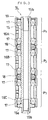
- Fig. 2 is a sectional view showing a pivot assembly 14 of the HSA 11.
- the pivot assembly 14 includes a first pivot P 1 , which has a sleeve 16A supported through bearings 17 onto a shaft 15, a second pivot P 2 , which has a sleeve 16B supported through bearings 17 onto the shaft 15, and a spacer 18 interposed between the sleeves 16A and 16B.
- the bearing 17 is preferably in the form of a radial ball bearing.
- the spacer 18 is brought into contact with inner race member (not shown) of the bearings 17 to properly keep a setting clearance between the first and second pivots P 1 and P 2 .
- the lower bearing 17 in the second pivot P 2 in Fig. 2 is brought into contact with a flange portion 15a formed on the shaft 15. This makes it possible to apply desired pre-loads onto the respective bearings 17 by applying an axial load onto an inner race member (not shown) of the upper bearing 17 in the first pivot P 1 in Fig. 2.
- the shaft 15 is formed as a hollow shaft, and female threads 15b are formed on both ends thereof to ease the fixing of the shaft 15.
- the portion designated by reference numeral 19 is a hub cap provided for the purpose of preventing particles from entering into the interior of the pivot assembly 14, and preventing dusts from being discharged outside the pivot assembly 14.
- actuator blocks 3 are respectively fixed to the sleeves 16A and 16B of the first and second pivots P 1 and P 2 so that the actuator blocks 3 are independently rotatable, while being arranged such that the rotational axes thereof are arranged in series.
- the embodiment of the present invention thus constructed provides the following effects: First of all, since the two actuator blocks 3 are supported such that one is independently rotatable to the other, the position of the magnetic heads to be accessed to different magnetic disks can be controlled independently by the actuator block 3 basis. Therefore, it is possible to distribute the reading/writing processing to the plural magnetic disks and perform these processing in parallel, to thereby increase the data reading/writing speed while increasing the storage capacity. If two actuator blocks 3 are provided as in the embodiment of the present invention, the data reading/writing speed becomes roughly as twice as fast in comparison to the conventional art in which all of the magnetic heads are supported by a single actuator block.
- first and second pivots P 1 and P 2 are supported rotatably onto the common shaft 15, the shaft 15, the pivot assembly 14, the actuator blocks 3 rotatably supported to the pivot assembly 14, and head suspensions 2 supported to the respective actuator blocks 3 can be formed as a module. Accordingly, even if the number of magnetic heads, the head suspensions 2, etc, are increased in association with the increase in number of multiple-stages of the magnetic disks D, there arises no inconvenience in handling during assembly.
- two independent shafts respectively for the first and second pivots P 1 and P 2 arranged in series may be employed, in order to allow the two actuator blocks 3 to be rotated independently in a state that their rotational axes are arranged in series.
- the use of the independent shafts makes it easier to change the setting clearance between the first and second pivots P 1 and P 2 , and accordingly the shaft arrangement or structure is preferably selected depending on the internal structure of the hard disk drive or the like.
- the provision of the spacer between the sleeves 16A and 16B supported through the bearings 17 onto the shaft 15 properly holds the setting clearance between the actuator blocks 3 fixed to the respective sleeves 16A and 16B, and enables the application of desired pre-loads to the bearings located inside the pivot assembly 14. This makes it possible to provide HSA 11 with high operational accuracy.
- first, second and third pivots P 1 , P 2 and P 3 may be provided such that the third pivot P 3 has a sleeve 16C supported through the bearings 17 onto the shaft 15, and another spacer 18 is disposed between the sleeves 16B and 16C. That is, the invention can freely cope with the multiple-staged magnetic disks D.
- the pivot assembly 14 in which five pivots are stacked can be constructed.
- the actuator block 3 is constructed to have multiple-staged suspension support portions 3a (Fig. 4) for supporting the head suspensions 2.
- the actuator block 3 may have a single suspension support portion 3a.
- the respective head suspensions 2 can be pivoted independently while the entire length of the pivot assembly 14 can be made substantially equal to the conventional pivot assembly 4 shown in Fig. 4.
- the present invention is constructed as mentioned above, the following effects can be obtained.
- a magnetic storage device for computers such as a hard disk drive
- the reading speed can be made faster, and there arises no inconvenience in handling during assembly.
- a magnetic storage device for computers such as a hard disk drive
- it is possible to realize a magnetic storage device for computers such as a hard disk drive, to meet all the requirements, i.e. miniaturization in size, the increased capacity, and the increased data reading/writing speed. Therefore, it is possible to enhance the performance of the magnetic storage device for computers.
Landscapes
- Moving Of Heads (AREA)
- Moving Of Head For Track Selection And Changing (AREA)
Abstract
Description
Claims (4)
- A head stack assembly comprising a pivot assembly provided with a plurality of pivots that support a plurality of actuator blocks supporting head suspensions so as to be independently rotatable, while being arranged so that rotational axes thereof are made in series.
- The head stack assembly as claimed in claim 1, wherein the plurality of pivots are axially supported to a common shaft.
- The head stack assembly as claimed in claim 2, further comprising the sleeves supported through bearings to the shaft, and a spacer disposed between the adjacent sleeves.
- A supporting method of a head stack assembly, wherein a plurality of actuator blocks supporting head suspensions are supported so as to be independently rotatable while being arranged such that rotational axes thereof are made in series.
Applications Claiming Priority (2)
| Application Number | Priority Date | Filing Date | Title |
|---|---|---|---|
| JP22256699 | 1999-08-05 | ||
| JP11222566A JP2001052453A (en) | 1999-08-05 | 1999-08-05 | Heat stack assembly and supporting method therefor |
Publications (2)
| Publication Number | Publication Date |
|---|---|
| EP1074979A2 true EP1074979A2 (en) | 2001-02-07 |
| EP1074979A3 EP1074979A3 (en) | 2006-04-05 |
Family
ID=16784478
Family Applications (1)
| Application Number | Title | Priority Date | Filing Date |
|---|---|---|---|
| EP00113750A Withdrawn EP1074979A3 (en) | 1999-08-05 | 2000-06-29 | Head stack assembly, and support method thereof |
Country Status (3)
| Country | Link |
|---|---|
| US (1) | US6449130B1 (en) |
| EP (1) | EP1074979A3 (en) |
| JP (1) | JP2001052453A (en) |
Cited By (2)
| Publication number | Priority date | Publication date | Assignee | Title |
|---|---|---|---|---|
| US6819513B2 (en) * | 2002-01-02 | 2004-11-16 | Hitachi Global Storage Technologies Netherlands B.V. | Low power hard disk drive using multiple, individually controllable actuators |
| US7315429B2 (en) | 2005-07-28 | 2008-01-01 | International Business Machines Corporation | Apparatus, method and program product for a multi-controller and multi-actuator storage device |
Families Citing this family (29)
| Publication number | Priority date | Publication date | Assignee | Title |
|---|---|---|---|---|
| US6678120B2 (en) * | 2000-04-10 | 2004-01-13 | James Bryant Money | Multiple-modular actuators having a common axis of rotation |
| US7031116B2 (en) * | 2000-08-30 | 2006-04-18 | Seagate Technology Llc | Moving magnet voice coil motor using Halbach arrays |
| US6560075B2 (en) * | 2001-04-10 | 2003-05-06 | Hitachi Global Storage Technologies | Disk drive with multiple actuators and reduced actuator interactions |
| CN1508793A (en) * | 2002-12-12 | 2004-06-30 | ���µ�����ҵ��ʽ���� | Head supporting device, driving method thereof, and disk device using the same |
| US9025277B1 (en) | 2013-10-10 | 2015-05-05 | HGST Netherlands B.V. | Hard disk drive having multiple disk stacks on a rotatable platform |
| US8958173B1 (en) | 2013-10-17 | 2015-02-17 | HGST Netherlands B.V. | Hard disk drive having multiple movable disk stacks on a guide rail |
| US8958172B1 (en) | 2013-10-17 | 2015-02-17 | HGST Netherlands B.V. | Multiple disk stack, single actuator hard disk drive |
| US8824094B1 (en) | 2013-10-18 | 2014-09-02 | HGST Netherlands B.V. | Hard disk drive having multiple disk stacks and a movable head stack assembly |
| US9142246B1 (en) | 2014-10-10 | 2015-09-22 | Seagate Technology Llc | Apparatus and methods to reduce hard disk drive manufacturing test time |
| US9361919B1 (en) | 2014-10-10 | 2016-06-07 | Seagate Technology Llc | Disk drive with parallel head actuation |
| US9911442B1 (en) | 2016-11-23 | 2018-03-06 | Seagate Technology Llc | Feedforward compensation for multi-actuator hard drives |
| US10332555B1 (en) * | 2017-06-07 | 2019-06-25 | Western Digital Technologies, Inc. | Reducing vibration transmission in a dual actuator disk drive utilizing a single pivot shaft |
| US10186287B2 (en) | 2017-06-07 | 2019-01-22 | Western Digital Technologies, Inc. | Split-shaft pivot for a dual-actuator hard disk drive |
| US10186286B2 (en) * | 2017-06-07 | 2019-01-22 | Western Digital Technologies, Inc. | Techniques for reducing dynamic coupling of system modes in a dual actuator hard disk drive |
| US10276194B2 (en) * | 2017-06-21 | 2019-04-30 | Western Digital Technologies, Inc. | Split-shaft pivot with interface spacer for a dual-actuator hard disk drive |
| JP6786542B2 (en) * | 2018-03-19 | 2020-11-18 | 株式会社東芝 | Disk device |
| JP2019164851A (en) | 2018-03-19 | 2019-09-26 | 株式会社東芝 | Disk device |
| US10446180B1 (en) | 2018-03-21 | 2019-10-15 | Seagate Technology Llc | Multi-actuator interconnector |
| US10255943B1 (en) | 2018-05-17 | 2019-04-09 | Seagate Technology Llc | Independent head, dual reader control logic |
| US10891980B1 (en) | 2018-05-25 | 2021-01-12 | Western Digital Technologies, Inc. | Central support for improved structural dynamics of actuators in a multi-actuator hard disk drive |
| EP3680515B1 (en) * | 2018-11-16 | 2024-04-10 | Roller Bearing Company of America, Inc. | Maintenance free extended life cam follower for a necker machine |
| US10839834B2 (en) * | 2018-11-30 | 2020-11-17 | Minebea Mitsumi Inc. | Pivot assembly bearing device and pivot assembly bearing device fabrication method |
| JP2020155176A (en) * | 2019-03-19 | 2020-09-24 | 株式会社東芝 | Disk device |
| US10803893B1 (en) | 2019-06-03 | 2020-10-13 | Seagate Technology Llc | Data transfer scheduling for fairness and balance |
| US10964345B1 (en) | 2020-05-22 | 2021-03-30 | Seagate Technology Llc | Parallel servo control in a data storage device |
| US11348607B1 (en) * | 2021-06-21 | 2022-05-31 | Western Digital Technologies, Inc. | Management of actuator dynamics in a multiple actuator hard disk drive with an unequal number of heads on the two outer arms of each actuator |
| US11942121B2 (en) | 2022-07-27 | 2024-03-26 | Western Digital Technologies, Inc. | Anchoring structure for improved structural dynamics of actuators in a multi-actuator hard disk drive |
| US12230303B2 (en) | 2022-09-22 | 2025-02-18 | Western Digital Technologies, Inc. | Center structure having attachment support for an actuator in a multi-actuator hard disk drive |
| US12176013B2 (en) | 2023-02-14 | 2024-12-24 | Western Digital Technologies, Inc. | Extended center stiffener plate for improved structural dynamics of actuators in a multi-actuator hard disk drive |
Family Cites Families (4)
| Publication number | Priority date | Publication date | Assignee | Title |
|---|---|---|---|---|
| JPS5823362A (en) * | 1981-07-30 | 1983-02-12 | Nippon Telegr & Teleph Corp <Ntt> | Shaking actuator |
| DE3412231A1 (en) * | 1984-04-02 | 1985-10-03 | Nixdorf Computer Ag, 4790 Paderborn | CARRIER ARRANGEMENT FOR MAGNETIC HEADS OF A MAGNETIC DISK DRIVE |
| US5134532A (en) * | 1989-06-28 | 1992-07-28 | Svendsen Peter R | Multiple-disk storage system |
| US5805386A (en) * | 1996-12-24 | 1998-09-08 | Texas Instruments Incorporated | Dual mode independent suspension read/write head assemblies in a hard disk drive |
-
1999
- 1999-08-05 JP JP11222566A patent/JP2001052453A/en active Pending
-
2000
- 2000-06-16 US US09/594,688 patent/US6449130B1/en not_active Expired - Fee Related
- 2000-06-29 EP EP00113750A patent/EP1074979A3/en not_active Withdrawn
Cited By (3)
| Publication number | Priority date | Publication date | Assignee | Title |
|---|---|---|---|---|
| US6819513B2 (en) * | 2002-01-02 | 2004-11-16 | Hitachi Global Storage Technologies Netherlands B.V. | Low power hard disk drive using multiple, individually controllable actuators |
| US7315429B2 (en) | 2005-07-28 | 2008-01-01 | International Business Machines Corporation | Apparatus, method and program product for a multi-controller and multi-actuator storage device |
| US7492542B2 (en) | 2005-07-28 | 2009-02-17 | International Business Machines Corporation | Method for storing and accessing data from a multi-controller and multi-actuator storage device |
Also Published As
| Publication number | Publication date |
|---|---|
| EP1074979A3 (en) | 2006-04-05 |
| US6449130B1 (en) | 2002-09-10 |
| JP2001052453A (en) | 2001-02-23 |
Similar Documents
| Publication | Publication Date | Title |
|---|---|---|
| US6449130B1 (en) | Head stack assembly enabling independent control of a position of magnetic heads for access to different magnetic disks and support method thereof | |
| US6687092B2 (en) | Pivot bearing assembly for compensating for disk drive actuator tilt | |
| JP2002100128A (en) | Magnetic disk unit | |
| US20080055773A1 (en) | Multi-Platter Flexible Media Disk Drive Arrangement | |
| US6172844B1 (en) | Double grooved spacer for a disc drive | |
| US10186287B2 (en) | Split-shaft pivot for a dual-actuator hard disk drive | |
| US5983485A (en) | Dual disc drive actuator assembly fabrication | |
| US6057990A (en) | Multiple actuator assemblies for data storage devices | |
| US7133250B2 (en) | Inboard thrust surface fluid recirculation pump | |
| US20050146809A1 (en) | Pivot integrated actuator assembly for a hard disk drive | |
| US6687094B2 (en) | Head actuator for a data storage head having a low mass with lateral stiffness | |
| US6679632B2 (en) | Lubricant retention design for disk drive fluid dynamic bearing spindle motor | |
| US20080019037A1 (en) | Disk spacer and hard disk drive having the same | |
| US6735044B2 (en) | Magnetic disk apparatus with humidity controller | |
| US20030222523A1 (en) | Spindle motor stator magnet axial bias | |
| US6201661B1 (en) | Disc slip preventing spacer ring apparatus and method of use | |
| US20070263321A1 (en) | System and method for integrated spindle balance and contamination control for disk drives | |
| US6406191B1 (en) | Pivot assembly | |
| US8929033B2 (en) | Flexure for implementation on a suspension in a hard disk drive for resisting windage effects | |
| US7420779B2 (en) | Disk apparatus having suspension provided with head support projections | |
| US7035045B2 (en) | Balance clip holder feature on a spindle motor with nickel-teflon coating on balance clips for reducing friction during clip adjustment in balance process | |
| JPH07130136A (en) | Magnetic disk unit | |
| US7283325B2 (en) | Apparatus and system for centering media disks on the hub of a spindle motor in a hard disk drive | |
| JP2004270797A (en) | Bearing device, head support device, and recording / reproducing device | |
| US20060256467A1 (en) | Spindle motor for hard disk drive |
Legal Events
| Date | Code | Title | Description |
|---|---|---|---|
| PUAI | Public reference made under article 153(3) epc to a published international application that has entered the european phase |
Free format text: ORIGINAL CODE: 0009012 |
|
| AK | Designated contracting states |
Kind code of ref document: A2 Designated state(s): AT BE CH CY DE DK ES FI FR GB GR IE IT LI LU MC NL PT SE |
|
| AX | Request for extension of the european patent |
Free format text: AL;LT;LV;MK;RO;SI |
|
| PUAL | Search report despatched |
Free format text: ORIGINAL CODE: 0009013 |
|
| AK | Designated contracting states |
Kind code of ref document: A3 Designated state(s): AT BE CH CY DE DK ES FI FR GB GR IE IT LI LU MC NL PT SE |
|
| AX | Request for extension of the european patent |
Extension state: AL LT LV MK RO SI |
|
| AKX | Designation fees paid |
Designated state(s): DE FR GB IT SE |
|
| STAA | Information on the status of an ep patent application or granted ep patent |
Free format text: STATUS: THE APPLICATION IS DEEMED TO BE WITHDRAWN |
|
| 18D | Application deemed to be withdrawn |
Effective date: 20061006 |