EP1074976A2 - Block switching based subband audio coder - Google Patents
Block switching based subband audio coder Download PDFInfo
- Publication number
- EP1074976A2 EP1074976A2 EP00116221A EP00116221A EP1074976A2 EP 1074976 A2 EP1074976 A2 EP 1074976A2 EP 00116221 A EP00116221 A EP 00116221A EP 00116221 A EP00116221 A EP 00116221A EP 1074976 A2 EP1074976 A2 EP 1074976A2
- Authority
- EP
- European Patent Office
- Prior art keywords
- acoustic signal
- blocks
- short
- sensation
- entropy
- Prior art date
- Legal status (The legal status is an assumption and is not a legal conclusion. Google has not performed a legal analysis and makes no representation as to the accuracy of the status listed.)
- Granted
Links
Images











Classifications
-
- G—PHYSICS
- G10—MUSICAL INSTRUMENTS; ACOUSTICS
- G10L—SPEECH ANALYSIS TECHNIQUES OR SPEECH SYNTHESIS; SPEECH RECOGNITION; SPEECH OR VOICE PROCESSING TECHNIQUES; SPEECH OR AUDIO CODING OR DECODING
- G10L19/00—Speech or audio signals analysis-synthesis techniques for redundancy reduction, e.g. in vocoders; Coding or decoding of speech or audio signals, using source filter models or psychoacoustic analysis
- G10L19/02—Speech or audio signals analysis-synthesis techniques for redundancy reduction, e.g. in vocoders; Coding or decoding of speech or audio signals, using source filter models or psychoacoustic analysis using spectral analysis, e.g. transform vocoders or subband vocoders
-
- G—PHYSICS
- G10—MUSICAL INSTRUMENTS; ACOUSTICS
- G10L—SPEECH ANALYSIS TECHNIQUES OR SPEECH SYNTHESIS; SPEECH RECOGNITION; SPEECH OR VOICE PROCESSING TECHNIQUES; SPEECH OR AUDIO CODING OR DECODING
- G10L19/00—Speech or audio signals analysis-synthesis techniques for redundancy reduction, e.g. in vocoders; Coding or decoding of speech or audio signals, using source filter models or psychoacoustic analysis
- G10L19/02—Speech or audio signals analysis-synthesis techniques for redundancy reduction, e.g. in vocoders; Coding or decoding of speech or audio signals, using source filter models or psychoacoustic analysis using spectral analysis, e.g. transform vocoders or subband vocoders
- G10L19/0204—Speech or audio signals analysis-synthesis techniques for redundancy reduction, e.g. in vocoders; Coding or decoding of speech or audio signals, using source filter models or psychoacoustic analysis using spectral analysis, e.g. transform vocoders or subband vocoders using subband decomposition
- G10L19/0208—Subband vocoders
Definitions
- the present invention relates to a digital acoustic signal coding apparatus, a method of coding a digital acoustic signal, and a recording medium for recording a program of coding the digital acoustic signal, in particular, the compression/coding of the digital acoustic signal utilized in, for instance, the DVD or the digital broadcast, etc.
- MP3 has been populariaed far and wide with great strides.
- the MP3 is an abbreviation of the acoustic signal compression coding method called "MPEG-1 Audio Layer III".
- MPEG-1 Audio Layer III the acoustic signal compression coding method
- the MP3 firstly starts to be popularized in the field of the internet.
- the reproducing apparatuses for use in the MP3 start to be announced one after another by the respective manufacturing companies, and some music distributing businesses start to be operated.
- the adoption of the sound signal (acoustic signal) compressing technology has been highly advanced.
- the method of MPEG-2 Audio BC is employed in the CS broadcasting.
- the method of MPEG-2 Audio AAC is scheduled to be employed in the BS or the digital broadcasting of the wave on the ground both to be started in 2000 or the subsequent years.
- the above-mentioned matters relates to the technology belonging to the international standard of the acoustic signal compression all called "MPEG Audio".
- MPEG Audio the acoustic signal compressing methods; Dolby Digital (AC-3) and ATRAC, are respectively employed for DVD and MD.
- the acoustic signal compressing method the acoustic signal is largely classified into "voice sound” and "musical sound".
- the voice sound signifies the human voice
- the musical sound signifies not only the human voice but the general acoustic signal including the music, the life sound, the natural sound, etc.
- the reason why the sound has to be classified is that the object and utilized technology of the coding differs from each other.
- the human voice signal of low sampling rate of almost 8-16 KHz is compressed for use in the low bit rate such as the telephone circuit.
- the acoustic signal of the high sampling rate of almost 32-96 KHz is compressed with the sound quality as high as possible.
- the deterioration of the sound quality cannot be avoided compared with the original sound, while, in the latter method, the sound compression fundamentally not deteriorated can be accomplished.
- Both of the MP3 and the AAC are included in the latter coding (musical sound coding).
- the technology of the musical sound coding is described.
- the method of compressing the digital information is classified into two methods; those are, reversible compression and non-reversible compression.
- the former method the original signal can be faithfully reproduced at the time of decoding.
- the latter method the distortion of the signal occurs generally.
- the acoustic signal compression coding method both of those methods are suitably combined.
- the reversible compression method is described.
- Huffman code employed also in the MPEG Audio as the representative reversible compression method is described.
- the Huffman coding is the method in which short code and long code are respectively allocated to the large frequency value and the small frequency value in accordance with the appearance frequency of the original signal value, and the signal is compressed such that the entire code value is made as small as possible.
- the code of the not-constant length is called a variable-length code, while the code of the equal (constant) length for all values is called a fixed-length code.
- the original signal of the acoustic compression is the fixed-length code represented by the bit number of the respective constant digital sample values (16 bit in the case of CD).
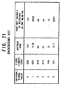
- Fig. 21 shows the example of the fixed-length code and the Huffman code
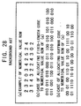
- Fig. 28 shows the example of allocating the code to the actual numerical value row utilizing the above-mentioned two codes.
- Fig. 21 shows the example of the fixed-length code and the Huffman code
- Fig. 28 shows the example of allocating the code to the actual numerical value row utilizing the above-mentioned two codes.
- the original signal row can be decoded in one meaning.
- the Huffman code row is "00110"
- the original signal row is "20" apparently. Since the one-meaning property of decoding is secured, the Huffman coding is reversible.
- the Huffman code when employed, the original signal value can be faithfully reproduced with further small code amount, compared with the fixed-length code.
- the compression factor e.g., almost 77% in the upper limit. So, it is impossible to expect a high compression factor, e.g., 1/11 in such situation as mentioned above. Therefore, the technology of non-reversible compression is required inevitably.
- the basic quantization technology therefor is described hereinafter.
- the quantization signifies the method of classifying the level of the original signal value into plural steps and causing the values representing the respective3 levels to correspond to the restoring value (decoded) value.
- the above-mentioned method is described, referring to the example of Fig. 22.
- the original signal value is distributed as the integer of 0 ⁇ 59.
- the respective value has to be expressed with 6bit.
- the original signal value is quantized to 6 levels and caused to correspond to the respective restoring (decoded) values as shown in Fig. 22.
- the original signal value is divided by "10” and the decimal fraction part is removed (cut down).
- the above "10” is called the scale factor.
- the integer part of the quotient is limited to the six sorts of the value 0 ⁇ 5.
- the above method is called the "quantization”. As shown in Fig. 22, it is sufficient to express the value with 3-bit fixed-length code, and thereby the compression factor of 50% can be realized. Furthermore, if the quantized value is converted to the Huffman code corresponding to the respective appearance frequencies, the compression factor can be further improved.
- Fig. 22 shows the case of allocating the Huffman code in Fig. 21 as an example.
- the quantized value is firstly restored (decoded) from the Huffman code.
- the method can be performed with one meaning as mentioned before.
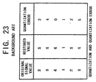
- the original signal value does not coincide the restored value in general, and therefore the error occurs.
- Such error called "quantization error”.
- the concrete example of the number is shown in Fig. 23.
- the quantization in the case of utilizing the quantization, the original signal value cannot be completely restored.
- the quantization although the quantization is non-reversible, the compression factor thereof can be improved, owing to that non-reversible quantization.
- the extent of the compression corresponds to the levels number of the quantization. The less the levels number is, the more largely the acoustic signal can be compressed. However, the average quantization error is increased.
- the Huffman code and the quantization both described heretofore are the most basic technology widely utilized for the compression of not only the acoustic signal but the static-picture and dynamic (moving)-picture signal.
- the aforementioned quantization error results in the deterioration of the sound quality in the acoustic signal compression.
- the acoustic signal data is required to be compressed to the extent of not sensing the deterioration of the sound quality.
- the masking effect is a phenomenon that the large sound erases (puts out or extinguishes) the surrounding small sound.
- the phenomenon has become widely familiar. To state a little more precisely, a strong sound of a certain frequency erases a weak sound of another frequency neighboring (in the neighborhood of) the above frequency.
- the detail of the above masking effect is further described hereinafter.
- the relationship between the frequency (KHz) represented by the horizontal coordinate (abscissa) and the sound intensity represented by the vertical coordinate (ordinate), and the sound intensity distribution of the input acoustic data on the both coordinates are described.
- the input sounds (b) and (c) is erased by the further strong sound (a) and both of (b) and (c) cannot be heard.
- the masking threshold value signifies a boundary (border line) between the audible sound and the inaudible sound.
- the human ears has an inherent characteristic having an absolute threshold value (or minimum audible threshold value). That represents the minimum sound (intensity) which human can hear in the calm environment.
- the human ears have the sharpest (most sharp) sensitivity for the sound in the neighborhood of 2KHz ⁇ 5KHz. The human ears become gradually unable to hear the sound of the frequency lower than 2KHz or higher than 5KHz.
- the masking threshold value changes in accordance with the input acoustic signal data.
- the absolute threshold value does not change at all.
- both of the above threshold values correspond to the tolerable upper limit of the aforementioned quantization error. Namely, when the input acoustic signal data is quantized, if the quantization error does not exceed the larger one of the both threshold value, the human ears do not sense the deterioration of the audible sound quality. In the area of the small threshold value, if the number of the quantization levels is not made large, the deterioration of the sound quality may become prominent. On the other hand, in the area of the large threshold value, it may be allowable to reduce the number of the quantization levels.
- the input acoustic data are generally represented (expressed) as the row of the digital sample value in the time direction.
- the aforementioned masking effect cannot be suitably applied as it is. For this reason, it is necessary to convert the row of the above-mentioned digital sample value to that to be easily processed.
- Fig. 24 shows the waveforms of the acoustic signals before and after the above conversion. To state concretely, Fig. 24A shows the waveform of the acoustic signal data row of 1,024 samples in the time area, and Fig. 24B shows the data row converted to the waveform of the acoustic signal data row of 1,024 samples in the frequency area.
- a deviation of the sound amount (energy) occurs in a certain frequency area.
- the signal value is uniformly distributed in the time area
- the energy of the acoustic signal in the frequency area is deviated to the low frequency side.
- the bit is distributed, putting emphasis, onto the part where the energy is concentrated. As the result, the compression efficiency can be further improved.
- DFT Digital Fourier Transform
- DCT Digital Cosine Transform
- MDCT Modified Digital Cosine Transform
- the subband division method (the band of) the input waveform is divided into plural frequency bands, and the respective divided waveform is kept to be that in the time area. This is a different point from the above method.
- Fig. 25 shows a simple example of dividing the input waveform into two subbands.
- the conversion of the input acoustic signal data to the data in the frequency area or the subband division is practiced for the input acoustic signal data.
- the respective sample values after conversion are quantized.
- the masking threshold value of the acoustic signal data are calculated in parallel, and the upper limit of the quantization error in the respective frequencies is previously obtained from the combination of the above calculated threshold value with the absolute threshold value.
- the above-mentioned step is performed by the audio psychology model part shown in Fig. 26.
- the quantization is performed such that the error does not exceed the upper limit thereof.
- the Huffman code is allocated in accordance with the appearance frequency of the respective quantization, and then the final coding data are created.
- the above step shows the outline of the most basic process of the acoustic signal compression coding.
- the practical coding method such as MP3, AAC, etc.
- various processes in addition to the above can be devised, and thereby the improvement of the compression factor can be intended to further improve the compression factor.
- Fig. 27 shows the flow of the coding process of MP3 putting focus on the subband division and the MDCT process.
- the big difference between the MP3 and the AAC is that the exist the subband division process before the MDCT in the MP3.
- the subband division signifies the division of the input data into plural frequency bands. The data are arranged on the time axis in the respective division areas.
- the input data is divided into 32 bands, and the MDCT is practiced per each of the respective divided bands.
- two sorts of the window function of LONG/SHORT can be used properly.
- the length of LONG is 36 samples, while the length of SHORT is 12 samples.
- the MP3 can cause the LONG/SHORT to exist mixingly.
- the high frequency is used for the SHORT and the low frequency is used for the LONG, Needless to mention, it may be allowable to use the all frequency for the SHORT or for the LONG.
- the length of the LONG window is 2,048 samples.
- the psychological property of the human hearing sense has been utilized up to now.
- the small sound is masked by the large sound.
- the small sound cannot be heard. Namely, when the large sound of a frequency is emitted, the small sound of other frequency near the above frequency cannot be heard by the human ears.
- the limited (critical) sound intensity which cannot be heard due to such masking is called "masking threshold value”.
- the human ears have the property that the sensitivity for the sound of the frequency near 4KHz is highest, and the more distant the frequency is from 4KHz, the lower the sensitivity for the sound of the same frequency becomes gradually.
- Such property is expressed as the critical sensitivity capable of sensing the sound in the calm situation, and the sensitivity is called "absolute audible threshold value".
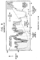
- Fig. 9 illustrating the intensity distribution of the acoustic signal.
- a stout solid line (A), a dotted line (B), and a fine solid line respectively represent the intensity distribution of the acoustic signal, the masking threshold value for the acoustic signal, and the absolute audible threshold value.
- the human eyes can sense only the sound of the intensity larger (stronger) than the masking threshold value and the absolute audible threshold value for the acoustic signal.
- the information is sensed by the human eyes to the same extent as the initial acoustic signal.
- the above matter is equivalent to allocating the coded bot only to the portions shown by the slanted lines in Fig. 9.
- the entire area of the acoustic signal is divided into plural small areas and the bit allocation is performed here in the unit of the divided band width (D).
- the transverse width of the respective areas shown by the slanted lines corresponds to the divided band width.
- the sound of the intensity not larger than that of the lower limit of the slanted area cannot be heard by the human ears. Therefore, if the intensity error of the original sound and the coded/decoded sound does not exceed the lower limit thereof, the difference between both of them cannot be sensed. In that sense, the lower-limit intensity is called "tolerable error intensity".
- the acoustic signal is quantized and compressed, if the quantization error intensity of the coded/decoded sound for the original sound is quantized so as to make it not larger than the tolerable error intensity, the acoustic signal can be compressed without damaging the quality of the original sound. Therefore, the allocation of the coded bit only to the slanted-line area shown in Fig. 9 is equivalent to performing the quantization such that the quantization error intensity in the respective divided band widths is just equal to the tolerable error intensity.
- Fig. 10 is a block diagram illustrating the fundamental structure of the AAC coding.
- an auditory sense psychology model section 101 calculates the tolerable error intensity per each of the respective band widths of the input acoustic signal separated into blocks along the time axis.
- MDCT Modified Discrete Cosine Transform
- a TNS Temporal Noise Shaping
- An estimation unit 106 perform the estimation coding.
- An intensity/coupling 105 and an MS Stereo(Middle Side Stereo) (hereinafter, called abbreviated "M/S”) 107 perform the stereo correlation coding process.
- M/S MS Stereo(Middle Side Stereo)
- normalizing coefficient 108 is determined.
- the acoustic signal is quantized in a quantizing unit 109 on the basis of the normalizing coefficient 108.
- the normalizing coefficient corresponds to the tolerable error intensity shown in Fig. 9, and the coefficient is determined per each of the respective divided band widths.
- the Huffman code is respectively given to the normalizing coefficient and the quantizing value in a noise coding (section) 110 on the basis of the predetermined Huffman code list.
- code bit stream is formed in a multiplexes 111.
- the MDCT in the aforementioned filter bank 103 is the one for overlapping the conversion areas by 50% along the time axis as shown in Fig. 11 and at the same time practicing DCT (Discrete Cosine Transform). Owing to such function, the occurrence of the distortion on the bordering part (boundary) of the respective conversion areas can be suppressed.
- DCT Discrete Cosine Transform
- AAC Advanced Audio Coding
- either one of the long conversion area (long block) of 2048 samples or the eight short conversion areas (short blocks) of respective 256 samples is applied for the input acoustic signal block. Consequently, the number of the MDCT coefficients is 1024 for the long block and 128 for the short blocks. In the case of employing the short blocks, eight blocks are always applied successively and thereby the number of the MDCT coefficients turns out to be same as the MDCT coefficients number at the time of employing the long block.
- the long block is employed in the regular part of small variation in the signal waveform as shown in Fig. 12, while the short blocks are employed in the attack part of violent (sharp) variation in the signal waveform. It is important to employ the long and short blocks in the different ways. If the long block is applied to the signal as shown in Fig. 13, a noise called "pre-echo" occurs before the essential attack. On the contrary, if the short blocks are applied to the signal as shown in Fig. 12, the adequate bit allocation cannot be performed due to the insufficient resolution in the frequency area. As the result, the coding efficiency is lowered and the noise occurs. The matter is prominent, in particular, for the sound of low frequency.
- the short blocks there further arises a problem of dividing (separating) into groups.
- the dividing into groups signifies that the above-mentioned eight short blocks are put together into groups per each of the successive blocks of the same normalizing coefficient.
- the effect of reducing the amount of the information can be raised by making common the normalizing coefficient in the group.
- the Huffman code is allocated to the normalizing coefficient in the noiseless coding (section) 110 shown in Fig. 10 shown in Fig. 10
- the code is allocated not per each of the respective short blocks unit but per the group unit.
- Fig. 14 illustrates an example of dividing it into groups.
- the number of the groups is three.
- the number of the blocks in the top group (O-th group) is five, the number of the blocks in the next group (1st group) is 1, and the number of the blocks in the last group (2nd group) is two. If the dividing into groups is not performed suitably, that results in the increase of the code amount (number) and the lowering of the sound quality. If the dividing number of the groups is too large, the normalizing coefficient which should be able to be made common essentially turns out to be coded duplicately (doubly). As the result, the coding efficiency is lowered.
- the auditory sense psychology model section 101 shown in Fig. 10 performs the long/short judgment.
- An example of the long/short judgment method for the respective blocks to be noticed in the auditory sense psychology model section 101 is shown in the ISO/IEC13818-7. The outline of the judging process is explained hereinafter.
- Step 1 Reconstruction of the Acoustic Signal
- 1024 samples for the long block are newly read (included) and the signal system (series) of 2048 samples in addition to 1024 samples previously included in the new block is reconstructed, while 128 samples for the short blocks are newly read (included) and the signal system (series) of 256 samples in addition to 128 samples previously included in the new block is reconstructed.
- the acoustic signal of 2048 samples (256 samples) constructed in Step 1 is multiplied by the Hann window (Hanning). Furthermore, FFT (Fast Fourier Transform) is practiced and thereby 1024 (128) FFT coefficients are calculated.
- Step 3 Calculation of the Estimation Value of the FFT Coefficient
- the real number part and the imaginary number part of the respective FFT coefficients in the block being noticed at present is estimated from the real number part and the imaginary number part of the FFT coefficients of (per) preceding two blocks, and then the estimated values of 1024 (128) are respectively calculated.
- Step 4 Calculation of the Non-Estimation Possibility Value
- the respective non-estimation possibility values are calculated from the estimation values of the real number and the imaginary number of the respective FFT coefficients calculated in Step 2 and those of the respective FFT coefficients calculated in Step 3.
- the non-estimation possibility value takes a value between 0 and 1.
- the nearer to 0 the value is, the higher is the pure-sound property of the acoustic signal, while the nearer to 1 the value is , the higher is the noise property of the acoustic signal. In other words, the lawer fact shows that the pure-sound property is low.
- Step 5 Calculation of the Acoustic Signal Intensity and the Non-Estimation Possibility Value in the Respective Divided Band Width
- the divided band width corresponds to the one as shown in Fig. 9.
- the intensity of the acoustic signal is calculated on the basis of the respective FFT coefficients calculated in Step 2 per each of the respective divided band width.
- the non-estimation possibility value calculated in Step 4 is weighted with the intensity, and the non-estimation possibility value is calculated per each of the respective divided band width.
- Step 6 Folding-in (Convoiving) of the Intensity multiplied by the Expanse (Spreading) Function and the Non-Estimation Possibility Value
- the effects due to the acoustic signal intensity and the non-estimation possibility value of the other divided band width in the respective divided band widths is obtained by use of the expanse (spreading) function.
- the effects thus obtained are respectively folded in (convolved) and thereby normalized.
- the pure sound property index tb(b) C -0.299 - 0.43 log.(cb(b) ) is calculated on the basis of the folded-in (convolved) non-estimation possibility value (cb(b)) calculated in Step 6. Furthermore, the pure-sound property index is limited within the area between 0 and 1.
- the above matter shows that the nearer to 1 the index is, the higher is the pure sound property of the acoustic signal, while the nearer to 0 the index is, the higher is the noise property of the acoustic signal.
- Step 8 Calculation of the S/N Ratio (Signal-to-Noise Ratio)
- the S/N ratio (signal-to-noise ratio) is calculated on the basis of the pure sound property index calculated in Step 7, in the respective divided band widths.
- the property that the masking effect of the noise component is larger than that of the pure sound component is utilized generally.
- the ratio of the folded-in acoustic signal intensity and the masking threshold value is calculated on the basis of the S/N ratio calculated in Step 8, in the respective divided band widths.
- Step 10 Calculation of the Tolerable Error Intensity _ (Masking Threshold Value)
- the masking threshold value is calculated on the basis of the folded-in acoustic signal intensity calculated in Step 6 and the ratio of the acoustic signal intensity calculated in Step 9 and the masking threshold value, in the respective divided band widths.
- Step 11 Adjustment of the Pre-Echo and Consideration of the Absolute Audible (-Frequency) Threshold Value
- the pre-echo adjustment is performed for the masking threshold value calculated in Step 10 by use of the tolerable error intensity of the preceding block, in the respective divided band widths. Furthermore, larger value of the adjusted value and the absolute audio (-frequency) threshold value is employed as the tolerable error intensity of the present block.
- Step 12 Calculation of the Sensation Entropy
- the sensation entropy PE (perceptual Entropy) as defined in the equation (1) is respectively calculated for the long block and for the short blocks.
- w(b) represents the width of the divided bandwidth b
- nb(b) represents the tolerable error intensity in the divided band width b calculated in Step 11
- e(b) represents the intensity of the acoustic signal in the divided band width b calculated in Step 5.
- the PE is thought to correspond to the total of the square measures of the bit allocating areas (slanted-lines areas) as shown in Fig. 9.
- Step 13 Judgment of the Long/Short blocks
- Step S10 When the value of the PE (Step S10) for the long block calculated in Step 12 is larger than the predetermined constant (switch_pe), the noticed block is judged to be the short blocks (Steps S11 and S12). When the same value of the PE is smaller than the predetermined constant, the noticed block is judged to be the long block (Steps S11 and S13).
- the constant (switch_pe) is a value determined in dependence to the application.
- the method mentioned heretofore is the long/short judgment method described in ISO/IEC 13818-7.
- a suitable judgment is not always performed. Namely, the part to be essentially judged to be short is judged to be long (or vice versa) and thereby the sound quality is deteriorated on some occasions.
- a transient state detecting circuit 2 is constructed such that the input signal is taken in per each of the respective predetermined sections and the square sums thereof are respectively obtained, and the transient state of the above-mentioned signal in accordance with the variation rate (degree) over the at least two or more sections of the signal squarely summed per each of the respective sections.
- the transient state that is, the part in which the long/short varies only by performing the calculation of the square sum of the input signal on the time axis without performing any perpendicular (rectangular) conversion processing and filter processing.
- the sensation entropy is not considered by use of only the square sum of the input signal, the judgment coinciding with the audio property cannot be always judged. Consequently, there is a fear that the sound quality deteriorates.
- the input acoustic signal block is divided (classified) into several groups such that the difference between the maximum value and the minimum value of the sensation entropy regarding the respective short blocks in the same group.
- the groups number is 1, or when the groups number is 1 and the other condition is satisfied, the input acoustic signal block is converted to the frequency area with one long block, and in the other case, the signal block is converted to the frequency area with plural short blocks.
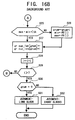
- the above-mentioned block is further concretely described hereinafter, referring to Fig. 16 illustrating the operation flow thereof.
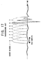
- the acoustic data shown in Fig. 17 are employed and the throughout numbers are attached corresponding to the respective successive eight short blocks in Fig. 17.
- the inputted acoustic signal is divided into the successive eight short blocks. And then, the sensation entropies of the eight short blocks are respectively calculated.
- the calculated values are assumed to be PE(i) (0 ⁇ i ⁇ 7) in order (Step S20).
- the calculation can be realized by performing, for the respective short blocks, the method explained in the Steps 1 through 12 of the long/short judgment method for the respective noticed blocks in the above-mentioned ISO/IEC 13818-7.
- gnum represents the through-out number of a certain group in the overall groups
- group_len [gnum] represents the number of the short blocks included in the gnum-th group
- min or max is renewed in accordance with PE(i). Namely, if PE(i) is smaller than min, min is equal to PE(i), or if PE(i) is larger than max, max is equal to PE(i).
- step S24) And the classification of the group is judged.
- step S25 Namely, the obtained value (max-min) is compared with the predetermined threshold value th.
- the step advances to the Step S26 in order to perform the group classification between the short blocks (i-1) and i.
- the value (max-min) is smaller than the value th, the short blocks (i-1) and i are judged to be included in the same group, and the step advances to the Step S27.
- the short blocks 0 and 1 are judged to be included in the same group, and the step advances to the Step S27.
- the short blocks 0 and 1 advance to the step S27.
- the short blocks 0 and 1 are included in the 0-th group, and increments, by one, the value of group_len [gnum] (Step S28). That signifies to inerease, by one, the number of the short blocks included in the gnum-th group.
- Step S28 the index i is incremented by 1 (Step S28).
- Step S29 the step returns to the Step S24 (Step S29).
- i 2 ⁇ 7
- the step returns to the Step S24.
- Step S25 the step advances to the Step S26. That signifies that the group classification is performed between the short blocks 4 and 5.
- the value of gnum is incremented by 1 in the Step S26, and the values of min and max are respectively replaced by the newest PE(i).
- the respective values of gnum, min, and max are 1, 152, and 152.
- the value of group_len [1] is incremented by 1 in the Step S27. Since the value of group_len [1] has been initialized to 0 (zero) at the Step S21, the value of group_len [1] becomes equal to 1 again in such state. That corresponds to the fact that one block in the block 5 as the short blocks included in the first group.
- i 6 in the Step S28 of Fig. 16.
- the step returns from the Step S29 to the Step S24, since the value of PE(6) becomes equal to 269, next time, as shown in Fig. 18, the values of min and max respectively become equal to 152 and 269.
- the energy of the original (initial) acoustic data is dispersed into the circumferential (peripheral) frequency band width due to the insufficient resolution in the frequency band width caused by the short blocks, and the energy further spreads out over the width of the masking in the low audio frequency which can be heard by the human ears.
- the human ears sense the deterioration of the sound quality.
- the input acoustic signal frame is divided into plural short blocks, and it is judged whether the pure sound property index of the acoustic component included in the predetermined one or plural divided band widths (areas) is larger than the threshold value.
- Zin case that there exists at least one short blocks larger than the aforementioned predetermined threshold value in all of the predetermined one or plural divided band widths (areas) it is judged that the input acoustic signal frame is converted to the frequency area with one long block.
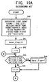
- Fig. 19 illustrates the concrete example of realizing such method.
- Fig. 19 is a flow chart illustrating the operation of a digital acoustic signal coding apparatus. The operation of the present embodiment is concretely described hereinafter, referring to Fig. 19. On this occasion, the acoustic data of Fig. 17 are employed as an example of the input acoustic signal. In Fig. 17, the through-out numbers are attached in correspondence with the respective eight successive short blocks.
- the inputted acoustic signal respectively calculates the values of the pure sound property index in the respective divided band widths sfb. Those calculated values are assumed to be tb[i][sfb] (Step S40).
- sfb is the through-out number for recognizing the respective divided band width.
- the calculation of the pure sound property index is performed by the method explained in the Step 7 in the long/short judgment step for the respective noticed blocks in the aforementioned ISO/IEC 13818-7.
- the initializing operation of tonal-flag 0 is done (Step S41).
- Step S45 the step returns again to the Step S43 via the Step S46.
- the judgment in the Step S43 becomes "Yes”, and the step advances to the Step S44.
- the value of tonal_flag becomes equal to 1 (Step S44).
- Tonal_flag 1
- Step S45 the step returns again to the Step S43 via the Step S43.
- the judgment in the Step S43 becomes "no", and the step advances to the Step S45.
- the value of tonal_flag is kept to 1 and does not change at all.
- Step S45 the step advances, at this time, to the Step S47 via the judgment of the Step S46, and then, the value of tonal_flag (Step S47).
- tonal_flag 1
- the present invention has been made in view of the above-mentioned problems and other problems in order to solve the above defects and troublesome matters of the background arts.
- the present invention improves the various problems of the background arts mentioned heretofore.
- the present invention provides the improved digital acoustic signal coding apparatus and method and the improved recording medium for recording the program of coding the digital acoustic signal.
- the object of the present invention is to solve the subject matters as mentioned heretofore. Even in the background-art method mentioned above, the judgment of long/short is not performed suitably on some occasions. That signifies that, in spite that the conversion by use of the short blocks(s) is essentially the usual method, since the result of the above-mentioned background-art group classification becomes 1 group, that is judged to be the long block on some occasions.
- the primary object of the present invention is to solve the above-mentioned matters as the subject matter thereof.
- the short blocks can be suitably classified into groups without deteriorating the sound quality, taking a countermeasure for the difference between the sampling frequencies of the input acoustic signal, and furthermore, the difference of long/short can be clearly judged (discriminated).
- the other object of the present invention is to provide a digital acoustic signal apparatus, a method of coding the digital acoustic signal, and a recording medium for recording thereon the digital acoustic signal coding program.
- FIG. 1 designate identical or corresponding parts throughout the several views (diagrams), and more particularly to Figs, 1 through 8 thereof, there are illustrated the improved digital acoustic signal coding apparatus, the improved method of coding the digital acoustic signal, and the improved medium for recording the program of coding the digital acoustic signal.
- the digital acoustic signal coding apparatus of the present invention is composed of a sensation entropy calculation medium for calculating the sensation entropy of an input acoustic signal calculated per each of the respective short conversion blocks; a sensation entropy sum total calculating medium for obtaining the sum total in the frame of the sensation entropy calculated by the sensation entropy calculation medium; a comparison medium for comparing the absolute value of the difference between the respective sum totals in the frame of the sensation entropy of the two frames being successive in relation to the elapsing time with a previously determined threshold value; and a long/short blocks judgment medium for judging whether the long block or the short blockshould convert the block of the input acoustic signal on the basis of the comparison result obtained by the comparison medium.
- the long/short blocks judgment medium judges that the later frame among the two frames successive in the elapsing time is converted by the short blocks; and, when the absolute value is smaller than the threshold value, the long/short blocks judgment medium judges that the later frame among the two frames is converted by the long block.
- the digital acoustic signal coding apparatus capable of performing the block conversion further reflecting (effectively utilizing) the property of the input acoustic signal.
- the other digital acoustic signal coding apparatus of the present invention is composed of a sensation entropy calculation medium for calculating the sensation entropy of a input acoustic signal calculated per each of the respective short conversion blocks; a sensation entropy sum total calculating medium for obtaining the sum total in the frame of the sensation entropy calculated by the sensation entropy calculation medium; a comparison medium for comparing the absolute value of the difference between the respective sum totals in the frame of the sensation entropy of the two frames being successive in relation to the elapsing time with a previously determined threshold value; and a judgment medium judging that the later frame among the two frames successive in the elapsing time is converted by the short blocks when the absolute value is larger than the threshold value as the comparison result obtained by said comparison medium, and that the judgment cannot be performed when the absolute value is smaller than the threshold value.
- the threshold value is equal to a value determined per the sampling frequency of the input acoustic signal.
- the method of coding digital acoustic signal of the present invention includes the steps of: calculating the sensation entropy of a input acoustic signal calculated per each of the respective short conversion blocks; obtaining the sum total in the frame of the calculated sensation entropy; comparing the absolute value of the difference between the respective sum totals in the frame of the sensation entropy of the two frames being successive in relation to the elapsing time with a previously determined threshold value; and judging whether the long block or the short blockshould convert the block of the input acoustic signal on the basis of the comparison result.
- the later frame among the two frames successive in the elapsing time is judged to be converted by the short blocks; and, when the absolute value is smaller than the threshold value, the later frame among the two frames is judged to be converted by the long block.
- the other method of coding digital acoustic signal of the present invention includes the steps of: calculating the sensation entropy of a input acoustic signal calculated per each of the respective short conversion blocks; obtaining the total sum in the frame of the calculated sensation entropy; comparing the absolute value of the difference between the respective sum totals in the frame of the sensation entropy of the two frames being successive in relation to the elapsing time with a previously determined threshold value; and judging the later frame among the two frames successive in the elapsing time to be converted by the short blocks when the absolute value is larger than the threshold value, and judging the later frame among the two frames successive in the elapsing time to be converted by the long block when the absolute value is smaller than the threshold value.
- the threshold value is equal to a value determined per the sampling frequency of the input acoustic signal.
- the apparatus for constructing the coding system can be widely used for various purposes, without changing the existing system.
- the above-mentioned computer program product or recording medium is further described later in more detail.
- the digital acoustic signal coding apparatus of the present invention in which a digital acoustic signal is inputted along time axis and divided into blocks therealong, processings such as sub-band division, conversion to frequency area, etc. are practiced per each of the respective blocks.
- the acoustic signal is divided into plural band widths. Coded bits are allocated to each of the respective band widths. Normalized coefficient is obtained corresponding to the coded bit number of the allocated bits.
- the digital acoustic signal is compressed and coded by quantizing the acoustic signal with the normalized coefficient.
- the conversion to the frequency area is performed, the acoustic signal divided the blocks is converted to either one of a long conversion block or plural short conversion blocks.
- the short conversion blocks are employed, the plural short conversion blocks are divided into the groups of plural blocks respectively including one or plural short conversion blocks.
- the acoustic signal is quantized causing one or plural short conversion block included in the same group to correspond to a common normalized coefficient.
- the digital acoustic signal coding apparatus is composed of a sensation entropy calculation medium for calculating the sensation entropy of a input acoustic signal calculated per each of the respective short conversion blocks; a sensation entropy total sum calculating medium for obtaining the total sum in the frame of the sensation entropy calculated by the sensation entropy calculation medium; a comparison medium for comparing the absolute value of the difference between the respective sum totals in the frame of the sensation entropy of the two frames being successive in relation to the elapsing time with a previously determined threshold value; and a long/short block judgment medium for judging whether the long block or the short blockshould convert the block of the input acoustic signal on the basis of the comparison result obtained by the comparison medium.
- Fig. 1 is a block diagram illustrating the structure of a digital acoustic signal coding apparatus relating to the first embodiment of the invention.
- the digital acoustic signal coding apparatus of the embodiment as shown in Fig. 1 is constructed with a block dividing medium 11 for dividing the inputted acoustic signal into the predetermined number of blocks, e.g., the eight successive blocks in the following explanation; a sensation entropy calculating medium 12 for calculating the sensation entropy PE of the respective divided blocks in accordance with the above-mentioned calculation formula; a sensation entropy total sum calculating medium 13 for obtaining the total sum in the frame of the calculated sensation entropy; a comparison medium 14 for comparing the absolute value of the difference between the respective total sums, in the frame, of the sensation entropy of the two frames which are successive in the elapsing time with the predetermined threshold value, and a long/short blocks judgment medium 15 for judging either one of the long block or short blocks in accord
- Fig. 2 is a flow chart illustrating the operation of the digital acoustic signal coding apparatus relating to the first embodiment of the invention.
- the operation of the embodiment is concretely described hereinafter, referring to Fig. 1 and Fig. 2.
- the acoustic data shown in Fig. 3 are employed as an example of the input acoustic signal.
- Fig. 3 shows 16 short blocks in total contained in the two frames which are successive in the elapsing time.
- the frame f-1 and the frame f are arranged in this time order.
- the noticed frame is the later frame f.
- the through-out numbers corresponding to the respective short blocks are attached to the respective frames.
- the acoustic signal is divided into blocks by the block dividing medium 11 and the sensation entropy calculating medium 12 respectively calculates the sensation entropy PE[f][I] for the successive eight short blocks I (0 ⁇ i ⁇ 7) in the frame f (Step S101).
- the calculation of the sensation entropy is performed by the method explained in the step 12 of the judgment method of the long/short blocks described in the aforementioned ISO/IEC 13818-7.
- the summing-up value SPE[f] with respect to 0 ⁇ i ⁇ 7 of PE[f][I] is obtained as defined in the below equation (2) by use of the sensation entropy total sum calculating medium 13 (Step S102).
- Step S103 The absolute value of the difference between the value of SPE [f-1] previously obtained in the similar way at the preceding frame f-1 by use of the comparing medium 14 and the value of SPE[f].
- the absolute value thus obtained is compared with the previously determined threshold value switch_pe_s, namely, the comparison which value is larger is done (Step S103). It is judged that, in the long/short blocks judgment medium 15, when the obtained absolute value is larger than the value switch_pe_s, the step advances to the Step S104 and the frame f is converted with the plural short blocks.
- the step advances to the Step S105 and the frame f is converted with the one (single) long block.
- Fig. 4 is a diagram (list) showing the values PE[f][I] corresponding to the respective short blocks shown in Fig. 3.
- the step S203 the absolute value of the difference between the value SPE[f-1] which is already obtained at the previous frame f-1 in the same way as mentioned above and the value SPE[f] and the absolute value thus obtained is compared with the predetermined threshold value switch_pe_s.
- the step advances to the step S204 and the frame f is judged to be converted with the plural short blocks.
- the judgment cannot be done only from the information regarding the difference between the total sum values of the sensation entropy of the respective short blocks in the frame and the long/short judgment is done with the other medium.
- the frame f is divided (classified) into the groups such that the difference between the maximum value and the minimum value of the sensation entropy regarding the respective short blocks in the same group becomes smaller than the predetermined threshold value.
- the step advances to the Step S206 and the frame f is converted to the frequency area with the one (single) long block.
- the step advances to the Step S204 and the conversion is judged to be done with the plural short blocks.
- the detail of the group classification is as shown in the flow chart of Fig. 16.
- switch-pe-s is equal to 500.
- the long/short judgment method employed in the Step S205 is not limited to the method based on the result of the group classification employed here. It is allowable to employ the other judgment method.
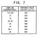
- switch_pe_s is determined in Fig. 2 and Fig. 5, it is also allowable to previously determine the value per each of the sampling frequencies of the input acoustic signal as in the case of Fig. 7 showing the example of the value of switch_pe_s per each of the sampling frequencies, and set the value of switch_pe_s referring to Fig. 7 in accordance with the sampling frequency of the acoustic signal inputted practically.
- Fig. 8 shows the hardware constructed with the microprocessor practicing the software by use of the digital acoustic signal coding method in the above-mentioned embodiment.
- the digital acoustic signal coding system is constructed with an interface (hereinafter, abbreviated as I/F) 81, a CPU 82, a ROM 83, a RAM 84, A displaying apparatus 85, a hard disc 86, a keyboard 87, and a CD-ROM drive 88.
- I/F interface
- the commonly-used processing apparatus is prepared, and the program for practicing the method of coding the digital acoustic signal according to the present invention is recorded in the recording medium capable of reading out the CD-ROM 89, etc.
- the control signal is inputted from the external apparatus via the I/F 81, and the operator issues the command (instruction) by operating the keyboard 87 or the program of the present invention is automatically initialized.
- the CPU 82 practices the coding control process accompanying the above-mentioned digital acoustic signal coding method in accordance with the above program.
- the result of the process is stored in the memorizing apparatus (memory) such as the RAM 84, the hard disc 86, etc.
- the information thus stored is outputted to the display apparatus as occasion demands.
- the apparatus for constructing the coding system can be commonly employed, without changing the system used at present.
- a recording medium of the present invention is employed for recording a computer program product or a program of coding the digital acoustic signal coding apparatus.
- the digital acoustic signal is inputted along time axis and divided into blocks therealong by use of a computer. Processings such as sub-band division or conversion to frequency area, etc. are practiced per each of the respective blocks.
- the acoustic signal is divided into plural band widths. Coded bits are allocated to each of the respective band widths. Normalized coefficient is obtained corresponding to the coded bit number of the allocated bits.
- the digital acoustic signal is compressed and coded by quantizing the acoustic signal with the normalized coefficient.
- the acoustic signal divided into the blocks is converted to either one of a long conversion block or plural short conversion blocks.
- the short conversion blocks are employed, the plural short conversion blocks are divided into the groups of plural blocks respectively including one or plural short conversion blocks.
- the acoustic signal is practiced to quantize causing one or plural short conversion block included in the same group to correspond to a common normalized coefficient.
- the medium has functions of: calculating the sensation entropy of a input acoustic signal calculated per each of the respective short conversion blocks; obtaining the total sum in the frame of said calculated sensation entropy; comparing the absolute value of the difference between the respective total sums in the frame of the sensation entropy of the two frames being successive in relation to the elapsing time with a previously determined threshold value; and judging whether the long block or the short blocks, should convert the block of said input acoustic signal on the basis of the comparison result.
- Another recording medium of the present invention is also employed for recording a program of coding the digital acoustic signal coding apparatus.
- the digital acoustic signal is inputted along time axis and divided into blocks therealong by use of a computer. Processings such as sub-band division or conversion to frequency area, are practiced per each of the respective blocks.
- the acoustic signal is divided into plural band widths. Coded bits are allocated to each of the respective band widths. Normalized coefficient is obtained corresponding to the coded bit number of the allocated bits.
- the digital acoustic signal is compressed and coded by quantizing the acoustic signal with the normalized coefficient.
- the acoustic signal divided into the blocks is converted to either one of a long conversion block or plural short conversion blocks.
- said plural short conversion blocks are divided into the groups of plural blocks respectively including one or plural short conversion blocks.
- the acoustic signal is practiced to quantize causing one or plural short conversion block included in the same group to correspond to a common normalized coefficient.
- the medium has functions of: calculating the sensation entropy of a input acoustic signal calculated per each of the respective short conversion blocks; obtaining the total sum in the frame of said calculated sensation entropy; comparing the absolute value of the difference between the respective total sums in the frame of the sensation entropy of the two frames being successive in relation to the elapsing time with a previously determined threshold value; and judging the later frame among the two frames successive in the elapsing time to be converted by the short blocks when the absolute value is larger than the threshold value, and judging the later frame among the two frames successive in the elapsing time to be converted by the long block when the absolute value is smaller than the threshold value.
- the digital acoustic signal coding apparatus the method of coding the digital acoustic signal, and the recording medium for recording the program of coding the digital acoustic signal, have been described.
- the embodiment of the present invention is featured in that the digital acoustic signal coding apparatus is constructed with the calculating medium for calculating the sensation entropy of the input acoustic signal, the total sum calculating medium for calculating the sensation entropy total sum in the frame, the comparing medium for comparing the absolute value of the difference between the respective total sums in the frame with the predetermined threshold value, and the long/short block judging medium for judging whether the long block or the short blocks convert the block of the input acoustic signal on the basis of the comparison result.
- the embodiment is featured in that the long/short block judgment medium judges that the later frame among the two frames successive in the elapsing time is converted by the short block when the absolute value is larger than the threshold value as the comparison result obtained by the comparison medium, while the long/short block judgment medium judges that the later frame among said two frames is converted by the long block when the absolute value is smaller than the threshold value.
- the other embodiment of the present invention is featured in that the digital acoustic signal coding apparatus is constructed with the calculating medium for calculating the sensation entropy of the input acoustic signal, the total sum calculating medium for calculating the sensation entropy total sum in the frame , the comparing medium for comparing the absolute value of the difference between the respective total sums in the frame with the predetermined threshold value, and the judgment medium judging that the later frame among the two frames successive in the elapsing time is converted by the short block when the absolute value is larger than the threshold value as the comparison result obtained by the comparison medium, and the judgment cannot be performed when the absolute value is smaller than the threshold value.
- the digital acoustic signal coding apparatus capable of performing the judgment of the block conversion further reflecting the property of the input acoustic signal.
- the threshold value is determined per each of the sampling frequencies of the input acoustic signal, and thereby the suitable long/short judgment can be performed corresponding to the difference between the sampling frequencies of the input acoustic signal.
- the method of coding digital acoustic signal comprises the steps of: calculating the sensation entropy of a input acoustic signal calculated per each of the respective short conversion blocks; obtaining the total sum in the frame of the calculated sensation entropy; comparing the absolute value of the difference between the respective total sums in the frame of the sensation entropy of the two frames being successive in relation to the elapsing time with a previously determined threshold value; and judging whether the long block or the short block should convert the block of the input acoustic signal on the basis of the comparison result.
- the method of coding digital acoustic signal comprises the steps of: calculating the sensation entropy of a input acoustic signal calculated per each of the respective short conversion blocks; obtaining the sum total in the frame of the calculated sensation entropy; comparing the absolute value of the difference between the respective sum totals in the frame of the sensation entropy of the two frames being successive in relation to the elapsing time with a previously determined threshold value; and judging the later frame among the two frames successive in the elapsing time to be converted by the short block when the absolute value is larger than the threshold value, and judging the later frame among the two frames successive in the elapsing time to be converted by the long block when the absolute value is smaller than the threshold value.
- the apparatus for constructing the coding system can be commonly used, without changing the system used heretofore.
Landscapes
- Engineering & Computer Science (AREA)
- Physics & Mathematics (AREA)
- Spectroscopy & Molecular Physics (AREA)
- Computational Linguistics (AREA)
- Signal Processing (AREA)
- Health & Medical Sciences (AREA)
- Audiology, Speech & Language Pathology (AREA)
- Human Computer Interaction (AREA)
- Acoustics & Sound (AREA)
- Multimedia (AREA)
- Compression, Expansion, Code Conversion, And Decoders (AREA)
Abstract
Description
Claims (11)
- A method of coding a digital acoustic signal comprising the steps of:inputting a digital acoustic signal along a time axis;dividing said digital acoustic signal into blocks therealong by use of a computer;practicing processings including a sub-band division or conversion to frequency area per each of the respective blocks;dividing said acoustic signal into plural band widths;allocating coded bits to each of said respective band widths;obtaining a normalized coefficient corresponding to the coded bit number of the allocated bits; andcompressing and coding said digital acoustic signal by quantizing said acoustic signal with said normalized coefficient,
wherein, when the conversion to said frequency area is performed, said acoustic signal divided into the blocks is converted to either one of a long conversion block or plural short conversion blocks;
wherein, when said short conversion blocks are employed, said plural short conversion blocks are divided into the groups of plural blocks respectively including one or plural short conversion blocks; and
wherein said acoustic signal is practiced to quantize causing one or plural short conversion block included in the same group to correspond to a common normalized coefficient;said method further comprising the steps of:calculating the sensation entropy of an input acoustic signal calculated per each of said respective short conversion blocks;obtaining said sum total in the frame of said calculated sensation entropy;comparing the absolute value of the difference between the respective sum totals in the frame of the sensation entropy of the two frames being successive in relation to the elapsing time with a previously determined threshold value; andjudging whether said long block or said short blocks should convert the block of said input acoustic signal on the basis of the comparison result. - Method according to claim 1,
wherein, when said absolute value is larger than said threshold value, the later frame among said two frames successive in the elapsing time is judged to be converted by said long block.
wherein, when said absolute value is smaller than said threshold value, the later frame among said two frames is judged to be converted by said long block. - A method of coding a digital acoustic signal comprising the steps of:inputting a digital acoustic signal along a time axis;dividing said digital acoustic signal into blocks therealong by use of a computer;practicing processings including a sub-band division or conversion to frequency area per each of the respective blocks;dividing said acoustic signal into plural band widths;allocating coded bits to each of said respective band widths;obtaining a normalized coefficient, corresponding to the coded bit number of the allocated bits; andcompressing and coding said digital acoustic signal by quantizing said acoustic signal with said normalized coefficient,
wherein, when the conversion to said frequency area is performed, said acoustic signal divided into the blocks is converted to either one of a long conversion block or plural short conversion blocks;
wherein, when said short conversion blocks are employed, said plural short conversion blocks are divided into the groups of plural blocks respectively including one or plural short conversion blocks; and
wherein said acoustic signal is practiced to quantize causing one or plural short conversion block included in the same group to correspond to a common normalized coefficient;said method further comprising the steps of:calculating the sensation entropy of an input acoustic signal calculated per each of said respective short conversion blocks;obtaining said sum total in the frame of said calculated sensation entropy;comparing the absolute value of the difference between the respective sum totals in the frame of the sensation entropy of the two frames being successive in relation to the elapsing time with a previously determined threshold value; andjudging the later frame among said two frames successive in the elapsing time to be converted by said short blocks, when said absolute value is larger than said threshold value, and judging the later frame among said two frames successive in the elapsing time to be converted by said long block, when said absolute value is smaller than said threshold value. - Method according to any of claims 1 to 3,
wherein said threshold value is equal to a value determined per the sampling frequency of said input acoustic signal. - Digital acoustic signal coding apparatus comprising means in which a digital acoustic signal is inputted along a time axis and divided into blocks therealong, processings including a sub-band division and conversion to frequency area are practiced per each of the respective block, said acoustic signal is divided into plural band widths, coded bits are allocated to each of said respective band widths, a normalized coefficient is obtained corresponding to the coded bit number of the allocated bits, and said digital acoustic signal is compressed and coded by quantizing said acoustic signal with said normalized coefficient,means for converting said acoustic signal divided into the blocks to either one of a long conversion block or plural short conversion blocks, when the conversion to said frequency area is performed;
means for dividing said plural short conversion blocks into the groups of plural blocks respectively including one or plural short conversion blocks, when said short conversion blocks are employed; andmeans for quantizing said acoustic signal, causing one or plural short conversion block included in the same group to correspond to a common normalized coefficient;said digital acoustic signal coding apparatus further comprising:sensation entropy calculation means (12) for calculating the sensation entropy of an input acoustic signal calculated per each of said respective short conversion blocks;sensation entropy total sum calculation means (13) for obtaining said total sum in the frame of said sensation entropy calculated by said sensation entropy calculation medium (12);comparison means (14) for comparing the absolute value of the difference between the respective total sums in the frame of the sensation entropy of the two frames being successive in relation to the elapsing time with a previously determined threshold value; andlong/short blocks judgment means (15) for judging whether said long block or said short blocks should convert the block of said input acoustic signal on the basis of the comparison result obtained by said comparison medium. - Apparatus according to claim 5,
wherein said long/short blocks judgment means (15) is adapted such that it judges that the later frame among said two frames successive in the elapsing time is converted by said short blocks, when said absolute value is larger than said threshold value as the comparison result obtained by said comparison medium; andthat it judges that the later frame among said two frames is converted by said long block, when said absolute value is smaller than said threshold value. - Digital acoustic signal coding apparatus comprising means in which a digital acoustic signal is inputted along a time axis and divided into blocks therealong, processings including a sub-band division and conversion to frequency area are practiced per each of the respective block, said acoustic signal is divided into plural band widths, coded bits are allocated to each of said respective band widths, a normalized coefficient is obtained corresponding to the coded bit number of the allocated bits, and said digital acoustic signal is compressed and coded by quantizing said acoustic signal with said normalized coefficient,means for converting said acoustic signal divided into the blocks to either one of a long conversion block or plural short conversion blocks, when the conversion to said frequency area is performed;means for dividing said plural short conversion blocks into the groups of plural blocks respectively including one or plural short conversion blocks, when said short conversion blocks are employed; andmeans for quantizing said acoustic signal, causing one or plural short conversion blocks included in the same group to correspond to a common normalized coefficient;said digital acoustic signal coding apparatus further comprising:sensation entropy calculation means for calculating the sensation entropy of an input acoustic signal calculated per each of said respective short conversion blocks;sensation entropy total sum calculating means for obtaining said total sum in the frame of said sensation entropy calculated by said sensation entropy calculation medium;comparison means for comparing the absolute value of the difference between the respective total sums in the frame of the sensation entropy of the two frames being successive in relation to the elapsing time with a previously determined threshold value; andjudgment means for judging that the later frame among said two frames successive in the elapsing time is converted by said short blocks, when said absolute value is larger than said threshold value as the comparison result obtained by said comparison medium, and that the judgment cannot be performed, when said absolute value is smaller than said threshold value.
- Apparatus according to any of claims 5 to 7,
wherein said threshold value is equal to a value determined per the sampling frequency of said input acoustic signal. - A computer program product directly loadable into the internal memory of a digital computer (82),comprising software code portions for performing the steps of any of claims 1 to 4, when said product is run on a computer.
- A computer program product stored on a recording medium usable by a digital acoustic signal coding apparatus comprising computer readable program means for inputting a digital acoustic signal along a time axis and dividing into blocks therealong, for practizing processings including a sub-band division or conversion to frequency area per each of the respective blocks, for dividing said acoustic signal into plural band widths, for allocating coded bits to each of said respective band widths, for obtaining a normalized coefficient corresponding to the coded bit number of the allocated bits, and for compressing and coding said digital acoustic signal by quantizing said acoustic signal with said normalized coefficient,computer readable program means for converting said acoustic signal divided into the blocks to either one of a long conversion block or plural short conversion blocks, when the conversion to said frequency area is performed;computer readable program means for dividing said plural short conversion blocks into the groups of plural blocks respectively including one or plural short conversion blocks, when said short conversion blocks are employed;computer readable program means for qantizing said acoustic signal causing one or plural short conversion block included in the same group to correspond to a common normalized coefficient;computer readable program means for calculating the sensation entropy of a input acoustic signal calculated per each of said respective short conversion blocks;computer readable program means for obtaining said sum total in the frame of said calculated sensation entropy;computer readable program means for comparing the absolute value of the difference between the respective sum totals in the frame of the sensation entropy of the two frames being successive in relation to the elapsing time with a previously determined threshold value; andcomputer readable program means for judging whether said long block or said short blocks, should convert the block of said input acoustic signal on the basis of the comparison result.
- A computer program product stored on a recording medium usable by a digital acoustic signal coding apparatus comprising computer readable program means for inputting a digital acoustic signal along a time axis and dividing into blocks therealong, for practizing processings including a sub-band division and a conversion to frequency area per each of the respective blocks, for dividing said acoustic signal into plural band widths, for allocating coded bits to each of said respective band widths, for obtaining a normalized coefficient corresponding to the coded bit number of the allocated bits, and for compressing and coding said digital acoustic signal by quantizing said acoustic signal with said normalized coefficient,computer readable program means for dividing said acoustic signal divided into the blocks to either one of a long conversion block or plural short conversion blocks, when the conversion to said frequency area is performed;computer readable program means for dividing said plural short conversion blocks into the groups of plural blocks respectively including one or plural short conversion blocks, when said short conversion blocks are employed;computer readable program means for quantizing said acoustic signal causing one or plural short conversion block included in the same group to correspond to a common normalized coefficient;computer readable program means for calculating the sensation entropy of an input acoustic signal calculated per each of said respective short conversion blocks;computer readable program means for obtaining said sum total in the frame of said calculated sensation entropy;computer readable program means for comparing the absolute value of the difference between the respective sum totals in the frame of the sensation entropy of the two frames being successive in relation to the elapsing time with a previously determined threshold value; andcomputer readable program means for judging the later frame among said two frames successive in the elapsing time to be converted by said short blocks when said absolute value is larger than said threshold value, and judging the later frame among said two frames successive in the elapsing time to be converted by said long block when said absolute value is smaller than said threshold value.
Applications Claiming Priority (2)
| Application Number | Priority Date | Filing Date | Title |
|---|---|---|---|
| JP22205499 | 1999-08-05 | ||
| JP22205499A JP3762579B2 (en) | 1999-08-05 | 1999-08-05 | Digital audio signal encoding apparatus, digital audio signal encoding method, and medium on which digital audio signal encoding program is recorded |
Publications (3)
| Publication Number | Publication Date |
|---|---|
| EP1074976A2 true EP1074976A2 (en) | 2001-02-07 |
| EP1074976A3 EP1074976A3 (en) | 2001-06-27 |
| EP1074976B1 EP1074976B1 (en) | 2004-10-20 |
Family
ID=16776386
Family Applications (1)
| Application Number | Title | Priority Date | Filing Date |
|---|---|---|---|
| EP00116221A Expired - Lifetime EP1074976B1 (en) | 1999-08-05 | 2000-08-04 | Block switching based subband audio coder |
Country Status (6)
| Country | Link |
|---|---|
| US (1) | US6799164B1 (en) |
| EP (1) | EP1074976B1 (en) |
| JP (1) | JP3762579B2 (en) |
| KR (1) | KR100348368B1 (en) |
| DE (1) | DE60015030T2 (en) |
| ES (1) | ES2231090T3 (en) |
Cited By (3)
| Publication number | Priority date | Publication date | Assignee | Title |
|---|---|---|---|---|
| WO2007008012A3 (en) * | 2005-07-11 | 2007-03-08 | Lg Electronics Inc | Apparatus and method of processing an audio signal |
| WO2019007969A1 (en) * | 2017-07-03 | 2019-01-10 | Dolby International Ab | Low complexity dense transient events detection and coding |
| US11232804B2 (en) | 2017-07-03 | 2022-01-25 | Dolby International Ab | Low complexity dense transient events detection and coding |
Families Citing this family (34)
| Publication number | Priority date | Publication date | Assignee | Title |
|---|---|---|---|---|
| US7006555B1 (en) | 1998-07-16 | 2006-02-28 | Nielsen Media Research, Inc. | Spectral audio encoding |
| US7532943B2 (en) * | 2001-08-21 | 2009-05-12 | Microsoft Corporation | System and methods for providing automatic classification of media entities according to sonic properties |
| US7035873B2 (en) | 2001-08-20 | 2006-04-25 | Microsoft Corporation | System and methods for providing adaptive media property classification |
| US7065416B2 (en) * | 2001-08-29 | 2006-06-20 | Microsoft Corporation | System and methods for providing automatic classification of media entities according to melodic movement properties |
| US7930170B2 (en) * | 2001-01-11 | 2011-04-19 | Sasken Communication Technologies Limited | Computationally efficient audio coder |
| JP4141235B2 (en) * | 2002-02-08 | 2008-08-27 | 株式会社リコー | Image correction apparatus and program |
| US20030215013A1 (en) * | 2002-04-10 | 2003-11-20 | Budnikov Dmitry N. | Audio encoder with adaptive short window grouping |
| US7349842B2 (en) * | 2003-09-29 | 2008-03-25 | Sony Corporation | Rate-distortion control scheme in audio encoding |
| US7325023B2 (en) | 2003-09-29 | 2008-01-29 | Sony Corporation | Method of making a window type decision based on MDCT data in audio encoding |
| US7426462B2 (en) * | 2003-09-29 | 2008-09-16 | Sony Corporation | Fast codebook selection method in audio encoding |
| US7283968B2 (en) * | 2003-09-29 | 2007-10-16 | Sony Corporation | Method for grouping short windows in audio encoding |
| US7516064B2 (en) * | 2004-02-19 | 2009-04-07 | Dolby Laboratories Licensing Corporation | Adaptive hybrid transform for signal analysis and synthesis |
| DE102004009949B4 (en) * | 2004-03-01 | 2006-03-09 | Fraunhofer-Gesellschaft zur Förderung der angewandten Forschung e.V. | Device and method for determining an estimated value |
| US7436969B2 (en) * | 2004-09-02 | 2008-10-14 | Hewlett-Packard Development Company, L.P. | Method and system for optimizing denoising parameters using compressibility |
| US7627481B1 (en) * | 2005-04-19 | 2009-12-01 | Apple Inc. | Adapting masking thresholds for encoding a low frequency transient signal in audio data |
| WO2006126856A2 (en) | 2005-05-26 | 2006-11-30 | Lg Electronics Inc. | Method of encoding and decoding an audio signal |
| EP1913578B1 (en) | 2005-06-30 | 2012-08-01 | LG Electronics Inc. | Method and apparatus for decoding an audio signal |
| US7565018B2 (en) * | 2005-08-12 | 2009-07-21 | Microsoft Corporation | Adaptive coding and decoding of wide-range coefficients |
| ATE453908T1 (en) | 2005-08-30 | 2010-01-15 | Lg Electronics Inc | DEVICE AND METHOD FOR DECODING AN AUDIO SIGNAL |
| US7646319B2 (en) | 2005-10-05 | 2010-01-12 | Lg Electronics Inc. | Method and apparatus for signal processing and encoding and decoding method, and apparatus therefor |
| US7672379B2 (en) | 2005-10-05 | 2010-03-02 | Lg Electronics Inc. | Audio signal processing, encoding, and decoding |
| KR100857118B1 (en) | 2005-10-05 | 2008-09-05 | 엘지전자 주식회사 | Method and apparatus for signal processing and encoding and decoding method, and apparatus therefor |
| US7696907B2 (en) | 2005-10-05 | 2010-04-13 | Lg Electronics Inc. | Method and apparatus for signal processing and encoding and decoding method, and apparatus therefor |
| EP1946063A4 (en) * | 2005-10-05 | 2009-08-12 | Lg Electronics Inc | Method and apparatus for signal processing and encoding and decoding method, and apparatus therefor |
| US7742913B2 (en) | 2005-10-24 | 2010-06-22 | Lg Electronics Inc. | Removing time delays in signal paths |
| JP2007183528A (en) * | 2005-12-06 | 2007-07-19 | Fujitsu Ltd | Encoding apparatus, encoding method, and encoding program |
| US7752053B2 (en) | 2006-01-13 | 2010-07-06 | Lg Electronics Inc. | Audio signal processing using pilot based coding |
| US20090144054A1 (en) * | 2007-11-30 | 2009-06-04 | Kabushiki Kaisha Toshiba | Embedded system to perform frame switching |
| US9313359B1 (en) | 2011-04-26 | 2016-04-12 | Gracenote, Inc. | Media content identification on mobile devices |
| US11140439B2 (en) | 2012-02-21 | 2021-10-05 | Roku, Inc. | Media content identification on mobile devices |
| EP2830063A1 (en) | 2013-07-22 | 2015-01-28 | Fraunhofer-Gesellschaft zur Förderung der angewandten Forschung e.V. | Apparatus, method and computer program for decoding an encoded audio signal |
| WO2016142002A1 (en) | 2015-03-09 | 2016-09-15 | Fraunhofer-Gesellschaft Zur Foerderung Der Angewandten Forschung E.V. | Audio encoder, audio decoder, method for encoding an audio signal and method for decoding an encoded audio signal |
| US9943253B2 (en) * | 2015-03-20 | 2018-04-17 | Innovo IP, LLC | System and method for improved audio perception |
| US10922139B2 (en) | 2018-10-11 | 2021-02-16 | Visa International Service Association | System, method, and computer program product for processing large data sets by balancing entropy between distributed data segments |
Family Cites Families (5)
| Publication number | Priority date | Publication date | Assignee | Title |
|---|---|---|---|---|
| EP0559348A3 (en) | 1992-03-02 | 1993-11-03 | AT&T Corp. | Rate control loop processor for perceptual encoder/decoder |
| US5537510A (en) * | 1994-12-30 | 1996-07-16 | Daewoo Electronics Co., Ltd. | Adaptive digital audio encoding apparatus and a bit allocation method thereof |
| EP0721257B1 (en) * | 1995-01-09 | 2005-03-30 | Daewoo Electronics Corporation | Bit allocation for multichannel audio coder based on perceptual entropy |
| US5699479A (en) * | 1995-02-06 | 1997-12-16 | Lucent Technologies Inc. | Tonality for perceptual audio compression based on loudness uncertainty |
| GB9819920D0 (en) * | 1998-09-11 | 1998-11-04 | Nds Ltd | Audio encoding system |
-
1999
- 1999-08-05 JP JP22205499A patent/JP3762579B2/en not_active Expired - Fee Related
-
2000
- 2000-08-04 EP EP00116221A patent/EP1074976B1/en not_active Expired - Lifetime
- 2000-08-04 ES ES00116221T patent/ES2231090T3/en not_active Expired - Lifetime
- 2000-08-04 KR KR1020000045308A patent/KR100348368B1/en not_active Expired - Fee Related
- 2000-08-04 US US09/633,290 patent/US6799164B1/en not_active Expired - Fee Related
- 2000-08-04 DE DE60015030T patent/DE60015030T2/en not_active Expired - Lifetime
Cited By (39)
| Publication number | Priority date | Publication date | Assignee | Title |
|---|---|---|---|---|
| WO2007008012A3 (en) * | 2005-07-11 | 2007-03-08 | Lg Electronics Inc | Apparatus and method of processing an audio signal |
| WO2007008011A3 (en) * | 2005-07-11 | 2007-03-15 | Lg Electronics Inc | Apparatus and method of processing an audio signal |
| US7830921B2 (en) | 2005-07-11 | 2010-11-09 | Lg Electronics Inc. | Apparatus and method of encoding and decoding audio signal |
| US7835917B2 (en) | 2005-07-11 | 2010-11-16 | Lg Electronics Inc. | Apparatus and method of processing an audio signal |
| US7930177B2 (en) | 2005-07-11 | 2011-04-19 | Lg Electronics Inc. | Apparatus and method of encoding and decoding audio signals using hierarchical block switching and linear prediction coding |
| US7949014B2 (en) | 2005-07-11 | 2011-05-24 | Lg Electronics Inc. | Apparatus and method of encoding and decoding audio signal |
| US7962332B2 (en) | 2005-07-11 | 2011-06-14 | Lg Electronics Inc. | Apparatus and method of encoding and decoding audio signal |
| US7966190B2 (en) | 2005-07-11 | 2011-06-21 | Lg Electronics Inc. | Apparatus and method for processing an audio signal using linear prediction |
| US7987009B2 (en) | 2005-07-11 | 2011-07-26 | Lg Electronics Inc. | Apparatus and method of encoding and decoding audio signals |
| US7987008B2 (en) | 2005-07-11 | 2011-07-26 | Lg Electronics Inc. | Apparatus and method of processing an audio signal |
| US7991272B2 (en) | 2005-07-11 | 2011-08-02 | Lg Electronics Inc. | Apparatus and method of processing an audio signal |
| US7991012B2 (en) | 2005-07-11 | 2011-08-02 | Lg Electronics Inc. | Apparatus and method of encoding and decoding audio signal |
| US7996216B2 (en) | 2005-07-11 | 2011-08-09 | Lg Electronics Inc. | Apparatus and method of encoding and decoding audio signal |
| US8010372B2 (en) | 2005-07-11 | 2011-08-30 | Lg Electronics Inc. | Apparatus and method of encoding and decoding audio signal |
| US8032368B2 (en) | 2005-07-11 | 2011-10-04 | Lg Electronics Inc. | Apparatus and method of encoding and decoding audio signals using hierarchical block swithcing and linear prediction coding |
| US8032240B2 (en) | 2005-07-11 | 2011-10-04 | Lg Electronics Inc. | Apparatus and method of processing an audio signal |
| US8032386B2 (en) | 2005-07-11 | 2011-10-04 | Lg Electronics Inc. | Apparatus and method of processing an audio signal |
| US8046092B2 (en) | 2005-07-11 | 2011-10-25 | Lg Electronics Inc. | Apparatus and method of encoding and decoding audio signal |
| US8050915B2 (en) | 2005-07-11 | 2011-11-01 | Lg Electronics Inc. | Apparatus and method of encoding and decoding audio signals using hierarchical block switching and linear prediction coding |
| US8055507B2 (en) | 2005-07-11 | 2011-11-08 | Lg Electronics Inc. | Apparatus and method for processing an audio signal using linear prediction |
| US8065158B2 (en) | 2005-07-11 | 2011-11-22 | Lg Electronics Inc. | Apparatus and method of processing an audio signal |
| US8108219B2 (en) | 2005-07-11 | 2012-01-31 | Lg Electronics Inc. | Apparatus and method of encoding and decoding audio signal |
| US8121836B2 (en) | 2005-07-11 | 2012-02-21 | Lg Electronics Inc. | Apparatus and method of processing an audio signal |
| US8149877B2 (en) | 2005-07-11 | 2012-04-03 | Lg Electronics Inc. | Apparatus and method of encoding and decoding audio signal |
| US8149878B2 (en) | 2005-07-11 | 2012-04-03 | Lg Electronics Inc. | Apparatus and method of encoding and decoding audio signal |
| US8149876B2 (en) | 2005-07-11 | 2012-04-03 | Lg Electronics Inc. | Apparatus and method of encoding and decoding audio signal |
| US8155152B2 (en) | 2005-07-11 | 2012-04-10 | Lg Electronics Inc. | Apparatus and method of encoding and decoding audio signal |
| US8155153B2 (en) | 2005-07-11 | 2012-04-10 | Lg Electronics Inc. | Apparatus and method of encoding and decoding audio signal |
| US8155144B2 (en) | 2005-07-11 | 2012-04-10 | Lg Electronics Inc. | Apparatus and method of encoding and decoding audio signal |
| US8180631B2 (en) | 2005-07-11 | 2012-05-15 | Lg Electronics Inc. | Apparatus and method of processing an audio signal, utilizing a unique offset associated with each coded-coefficient |
| US8255227B2 (en) | 2005-07-11 | 2012-08-28 | Lg Electronics, Inc. | Scalable encoding and decoding of multichannel audio with up to five levels in subdivision hierarchy |
| US8275476B2 (en) | 2005-07-11 | 2012-09-25 | Lg Electronics Inc. | Apparatus and method of encoding and decoding audio signals |
| US8326132B2 (en) | 2005-07-11 | 2012-12-04 | Lg Electronics Inc. | Apparatus and method of encoding and decoding audio signal |
| US8417100B2 (en) | 2005-07-11 | 2013-04-09 | Lg Electronics Inc. | Apparatus and method of encoding and decoding audio signal |
| US8510119B2 (en) | 2005-07-11 | 2013-08-13 | Lg Electronics Inc. | Apparatus and method of processing an audio signal, utilizing unique offsets associated with coded-coefficients |
| US8510120B2 (en) | 2005-07-11 | 2013-08-13 | Lg Electronics Inc. | Apparatus and method of processing an audio signal, utilizing unique offsets associated with coded-coefficients |
| US8554568B2 (en) | 2005-07-11 | 2013-10-08 | Lg Electronics Inc. | Apparatus and method of processing an audio signal, utilizing unique offsets associated with each coded-coefficients |
| WO2019007969A1 (en) * | 2017-07-03 | 2019-01-10 | Dolby International Ab | Low complexity dense transient events detection and coding |
| US11232804B2 (en) | 2017-07-03 | 2022-01-25 | Dolby International Ab | Low complexity dense transient events detection and coding |
Also Published As
| Publication number | Publication date |
|---|---|
| US6799164B1 (en) | 2004-09-28 |
| KR20010021226A (en) | 2001-03-15 |
| DE60015030T2 (en) | 2005-11-10 |
| JP2001053617A (en) | 2001-02-23 |
| EP1074976B1 (en) | 2004-10-20 |
| DE60015030D1 (en) | 2004-11-25 |
| JP3762579B2 (en) | 2006-04-05 |
| EP1074976A3 (en) | 2001-06-27 |
| KR100348368B1 (en) | 2002-08-10 |
| ES2231090T3 (en) | 2005-05-16 |
Similar Documents
| Publication | Publication Date | Title |
|---|---|---|
| EP1074976B1 (en) | Block switching based subband audio coder | |
| US6456963B1 (en) | Block length decision based on tonality index | |
| JP7177185B2 (en) | Signal classification method and signal classification device, and encoding/decoding method and encoding/decoding device | |
| US8615391B2 (en) | Method and apparatus to extract important spectral component from audio signal and low bit-rate audio signal coding and/or decoding method and apparatus using the same | |
| US8612215B2 (en) | Method and apparatus to extract important frequency component of audio signal and method and apparatus to encode and/or decode audio signal using the same | |
| US8428943B2 (en) | Quantization matrices for digital audio | |
| US6772111B2 (en) | Digital audio coding apparatus, method and computer readable medium | |
| CN109313908A (en) | Audio encoder for encoding audio signal, method for encoding audio signal and computer program considering detected peak spectral regions in upper frequency band | |
| JP2006011456A (en) | Low bit rate encoding / decoding method and apparatus and computer-readable medium | |
| US7634400B2 (en) | Device and process for use in encoding audio data | |
| US20040002854A1 (en) | Audio coding method and apparatus using harmonic extraction | |
| US8149927B2 (en) | Method of and apparatus for encoding/decoding digital signal using linear quantization by sections | |
| US20050091041A1 (en) | Method and system for speech coding | |
| US8781843B2 (en) | Method and an apparatus for processing speech, audio, and speech/audio signal using mode information | |
| US20050270195A1 (en) | Method and apparatus for encoding/decoding digital signal | |
| US20100057449A1 (en) | Apparatus and method of enhancing quality of speech codec | |
| US20060100885A1 (en) | Method and apparatus to encode and decode an audio signal | |
| CA3202969A1 (en) | Method and device for unified time-domain / frequency domain coding of a sound signal | |
| JP3813025B2 (en) | Digital audio signal encoding apparatus, digital audio signal encoding method, and medium on which digital audio signal encoding program is recorded | |
| US20070078651A1 (en) | Device and method for encoding, decoding speech and audio signal | |
| JP2000206990A (en) | Digital audio signal encoding device, digital audio signal encoding method, and medium recording digital audio signal encoding program | |
| JPH0746137A (en) | Highly efficient sound encoder | |
| JP2000276198A (en) | Digital audio signal encoding device, digital audio signal encoding method, and medium recording digital audio signal encoding program |
Legal Events
| Date | Code | Title | Description |
|---|---|---|---|
| PUAI | Public reference made under article 153(3) epc to a published international application that has entered the european phase |
Free format text: ORIGINAL CODE: 0009012 |
|
| AK | Designated contracting states |
Kind code of ref document: A2 Designated state(s): DE ES FR GB IT NL |
|
| AX | Request for extension of the european patent |
Free format text: AL;LT;LV;MK;RO;SI |
|
| PUAL | Search report despatched |
Free format text: ORIGINAL CODE: 0009013 |
|
| AK | Designated contracting states |
Kind code of ref document: A3 Designated state(s): AT BE CH CY DE DK ES FI FR GB GR IE IT LI LU MC NL PT SE |
|
| AX | Request for extension of the european patent |
Free format text: AL;LT;LV;MK;RO;SI |
|
| 17P | Request for examination filed |
Effective date: 20010824 |
|
| AKX | Designation fees paid |
Free format text: DE ES FR GB IT NL |
|
| GRAP | Despatch of communication of intention to grant a patent |
Free format text: ORIGINAL CODE: EPIDOSNIGR1 |
|
| GRAS | Grant fee paid |
Free format text: ORIGINAL CODE: EPIDOSNIGR3 |
|
| GRAA | (expected) grant |
Free format text: ORIGINAL CODE: 0009210 |
|
| AK | Designated contracting states |
Kind code of ref document: B1 Designated state(s): DE ES FR GB IT NL |
|
| REG | Reference to a national code |
Ref country code: GB Ref legal event code: FG4D |
|
| REF | Corresponds to: |
Ref document number: 60015030 Country of ref document: DE Date of ref document: 20041125 Kind code of ref document: P |
|
| REG | Reference to a national code |
Ref country code: ES Ref legal event code: FG2A Ref document number: 2231090 Country of ref document: ES Kind code of ref document: T3 |
|
| PLBE | No opposition filed within time limit |
Free format text: ORIGINAL CODE: 0009261 |
|
| STAA | Information on the status of an ep patent application or granted ep patent |
Free format text: STATUS: NO OPPOSITION FILED WITHIN TIME LIMIT |
|
| ET | Fr: translation filed | ||
| 26N | No opposition filed |
Effective date: 20050721 |
|
| PGFP | Annual fee paid to national office [announced via postgrant information from national office to epo] |
Ref country code: FR Payment date: 20090814 Year of fee payment: 10 Ref country code: ES Payment date: 20090827 Year of fee payment: 10 |
|
| PGFP | Annual fee paid to national office [announced via postgrant information from national office to epo] |
Ref country code: GB Payment date: 20090729 Year of fee payment: 10 Ref country code: NL Payment date: 20090816 Year of fee payment: 10 Ref country code: DE Payment date: 20090730 Year of fee payment: 10 |
|
| PGFP | Annual fee paid to national office [announced via postgrant information from national office to epo] |
Ref country code: IT Payment date: 20090813 Year of fee payment: 10 |
|
| REG | Reference to a national code |
Ref country code: NL Ref legal event code: V1 Effective date: 20110301 |
|
| GBPC | Gb: european patent ceased through non-payment of renewal fee |
Effective date: 20100804 |
|
| REG | Reference to a national code |
Ref country code: FR Ref legal event code: ST Effective date: 20110502 |
|
| PG25 | Lapsed in a contracting state [announced via postgrant information from national office to epo] |
Ref country code: IT Free format text: LAPSE BECAUSE OF NON-PAYMENT OF DUE FEES Effective date: 20100804 Ref country code: NL Free format text: LAPSE BECAUSE OF NON-PAYMENT OF DUE FEES Effective date: 20110301 |
|
| REG | Reference to a national code |
Ref country code: DE Ref legal event code: R119 Ref document number: 60015030 Country of ref document: DE Effective date: 20110301 |
|
| PG25 | Lapsed in a contracting state [announced via postgrant information from national office to epo] |
Ref country code: FR Free format text: LAPSE BECAUSE OF NON-PAYMENT OF DUE FEES Effective date: 20100831 Ref country code: DE Free format text: LAPSE BECAUSE OF NON-PAYMENT OF DUE FEES Effective date: 20110301 |
|
| PG25 | Lapsed in a contracting state [announced via postgrant information from national office to epo] |
Ref country code: GB Free format text: LAPSE BECAUSE OF NON-PAYMENT OF DUE FEES Effective date: 20100804 |
|
| REG | Reference to a national code |
Ref country code: ES Ref legal event code: FD2A Effective date: 20111019 |
|
| PG25 | Lapsed in a contracting state [announced via postgrant information from national office to epo] |
Ref country code: ES Free format text: LAPSE BECAUSE OF NON-PAYMENT OF DUE FEES Effective date: 20100805 |