EP1074968A1 - Synthesized sound generating apparatus and method - Google Patents
Synthesized sound generating apparatus and method Download PDFInfo
- Publication number
- EP1074968A1 EP1074968A1 EP00116813A EP00116813A EP1074968A1 EP 1074968 A1 EP1074968 A1 EP 1074968A1 EP 00116813 A EP00116813 A EP 00116813A EP 00116813 A EP00116813 A EP 00116813A EP 1074968 A1 EP1074968 A1 EP 1074968A1
- Authority
- EP
- European Patent Office
- Prior art keywords
- signal
- coefficients
- synthesized
- synthesized signal
- convolution
- Prior art date
- Legal status (The legal status is an assumption and is not a legal conclusion. Google has not performed a legal analysis and makes no representation as to the accuracy of the status listed.)
- Granted
Links
- 238000000034 method Methods 0.000 title claims abstract description 24
- 230000008569 process Effects 0.000 claims abstract description 12
- 230000008859 change Effects 0.000 claims abstract description 5
- 230000005236 sound signal Effects 0.000 claims description 9
- 230000015572 biosynthetic process Effects 0.000 abstract description 13
- 238000003786 synthesis reaction Methods 0.000 abstract description 13
- 238000010586 diagram Methods 0.000 description 8
- 230000003595 spectral effect Effects 0.000 description 5
- 238000010276 construction Methods 0.000 description 4
- 230000001755 vocal effect Effects 0.000 description 4
- 230000006870 function Effects 0.000 description 3
- 238000002592 echocardiography Methods 0.000 description 2
- 230000000694 effects Effects 0.000 description 2
- 230000004044 response Effects 0.000 description 2
- 230000002194 synthesizing effect Effects 0.000 description 2
- 230000009466 transformation Effects 0.000 description 2
- 101100328887 Caenorhabditis elegans col-34 gene Proteins 0.000 description 1
- 230000003111 delayed effect Effects 0.000 description 1
- 238000001514 detection method Methods 0.000 description 1
- 238000001914 filtration Methods 0.000 description 1
- 238000001228 spectrum Methods 0.000 description 1
- 238000001308 synthesis method Methods 0.000 description 1
Images




Classifications
-
- G—PHYSICS
- G10—MUSICAL INSTRUMENTS; ACOUSTICS
- G10H—ELECTROPHONIC MUSICAL INSTRUMENTS; INSTRUMENTS IN WHICH THE TONES ARE GENERATED BY ELECTROMECHANICAL MEANS OR ELECTRONIC GENERATORS, OR IN WHICH THE TONES ARE SYNTHESISED FROM A DATA STORE
- G10H1/00—Details of electrophonic musical instruments
- G10H1/02—Means for controlling the tone frequencies, e.g. attack or decay; Means for producing special musical effects, e.g. vibratos or glissandos
- G10H1/06—Circuits for establishing the harmonic content of tones, or other arrangements for changing the tone colour
- G10H1/12—Circuits for establishing the harmonic content of tones, or other arrangements for changing the tone colour by filtering complex waveforms
- G10H1/125—Circuits for establishing the harmonic content of tones, or other arrangements for changing the tone colour by filtering complex waveforms using a digital filter
-
- G—PHYSICS
- G10—MUSICAL INSTRUMENTS; ACOUSTICS
- G10H—ELECTROPHONIC MUSICAL INSTRUMENTS; INSTRUMENTS IN WHICH THE TONES ARE GENERATED BY ELECTROMECHANICAL MEANS OR ELECTRONIC GENERATORS, OR IN WHICH THE TONES ARE SYNTHESISED FROM A DATA STORE
- G10H7/00—Instruments in which the tones are synthesised from a data store, e.g. computer organs
- G10H7/08—Instruments in which the tones are synthesised from a data store, e.g. computer organs by calculating functions or polynomial approximations to evaluate amplitudes at successive sample points of a tone waveform
- G10H7/10—Instruments in which the tones are synthesised from a data store, e.g. computer organs by calculating functions or polynomial approximations to evaluate amplitudes at successive sample points of a tone waveform using coefficients or parameters stored in a memory, e.g. Fourier coefficients
Definitions
- the present invention relates to a synthesized sound generating apparatus and method which is suitable for inputting and synthesizing voices and instrumental sounds and outputting synthesized instrumental sounds or the like having characteristic information on the voices.
- Vocoders which have a function for analyzing and synthesizing voices, are commonly used with music synthesizers due to their ability to onomatopoeically generate instrumental sounds, noise, or the like.
- Major known developed vocoders include formant vocoders, linear predictive analysis and synthesis systems (PARCO analysis and synthesis), cepstrum vocoders (speech synthesis based on homomorphic filtering), channel vocoders (what is called Dudley vocoders), and the like.
- the formant vocoder uses a terminal analog synthesizer to carry out sound synthesis based on parameters for vocal tract characteristics determined from a formant and an anti-formant of a spectral envelope, that is, pole and zero points thereof.
- the terminal analog synthesizer is comprised of a plurality of resonance circuits and antiresonance circuits arranged in cascade connection for simulating resonance/antiresonance characteristics of a vocal tract.
- the linear predictive analysis and synthesis system is an extension of the predictive encoding method, which is most popular among the speech synthesis methods.
- the PARCO analysis and synthesis system is an improved version of the linear predictive analysis and synthesis system.
- the cepstrum vocoder is a speech synthesis system using a logarithmic amplitude characteristic of a filter and inverse Fourier transformation and inverse convolution of a logarithmic spectrum of a sound source.
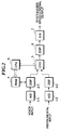
- the channel vocoder uses bandpass filters 10-1 to 10-N for different bands to extract spectral envelope information on an input speech signal, that is, parameters for the vocal tract characteristics, as shown in FIG. 1, for example.
- a pulse train generator 21 and a noise generator 22 generate two kinds of sound source signals, which are amplitude-modulated using the spectral envelope parameters. This amplitude modulation is carried out by multipliers (modulators) 30-1 to 30-N. Modulated signals output from the multipliers (modulators) 30-1 to 30-N pass through bandpass filters 40-1 to 40-N and are then added together by an adder 50 whereby a synthesized speech signal is generated and output.
- outputs from the bandpass filters 10-1 to 10-N are rectified and smoothed when passing through short-time average-amplitude detection circuits 60-1 to 60-N.
- a voice sound/unvoiced sound detector 71 determines a voice sound component and an unvoiced sound component of the input speech signal, and upon detecting the voice sound component, the detector 71 operates a switch 23 so as to select and deliver an output (pulse train) from the pulse train generator 21 to the multipliers 30-1 to 30-N.
- the voice sound/unvoiced sound detector 71 operates the switch 23 so as to select and deliver an output (noise) from the noise generator 22 to the multipliers 30-1 to 30-N.
- a pitch detector 72 detects a pitch of the input speech signal to cause it to be reflected in the output pulse train from the pulse generator 21.
- the output from the pulse generator 21 contains pitch information, which is among characteristic information on the input speech signal.
- the formant vocoder since the formant and anti-formant from the spectral envelope cannot be easily extracted, the formant vocoder requires a complicated analysis process or manual operation.
- the linear predictive analysis and synthesis system uses an all-pole model to generate sounds and uses a simple mean square value of prediction errors, as an evaluative reference for determining coefficients for the model. Thus, this method does not focus on the nature of voices.
- the cepstrum vocoder requires a large amount of time for spectral processing and Fourier transformation and is thus insufficiently responsive in real time.
- the channel vocoder directly expresses the parameters for the vocal tract characteristics in physical amounts in the frequency domain and thus takes the nature of voices into consideration. Due to the lack of mathematical strictness, however, the channel vocoder is not suited for digital processing.
- a synthesized sound generating apparatus comprising a coefficient generating means for generating coefficients by using dynamic cutting to extract characteristic information from a first signal; and a synthesized signal generating means for carrying out a convolution operation on a second signal using the coefficients generated by the coefficient generating means to generate a synthesized signal.
- the synthesized signal generating means comprises a convolution circuit that carries out an interpolation process on the coefficients to prevent a rapid change in level of the generated synthesized signal upon switching of the coefficients.
- the first signal is a speech signal
- the characteristic information extracted from the speech signal indicates one waveform starting at a zero cross point and ending at another zero cross point separated from the zero cross point by a time interval close to a reference switching cycle.
- the time interval is determined from an actual waveform of the speech signal.
- the second signal is an instrumental sound signal.
- a synthesized signal generating apparatus comprising a coefficient generating means for dynamically continuously cutting out waveforms from a first signal in a manner such that adjacent ones of the waveforms cut out from the first signal partly overlap each other, to extract characteristic information therefrom to generate coefficients, a convolution means for alternately receiving the coefficients generated from the waveforms continuously cut out by the coefficient generating means and carrying out convolution operations on a second signal using the coefficients to generate a first synthesized signal and a second synthesized signal, respectively, and a cross fade processing means for carrying out a cross fade process on the first synthesized signal and the second synthesized signal generated by the convolution means, upon switching of the coefficients.
- the first signal is a speech signal
- the characteristic information extracted from the speech signal indicates one waveform starting at a zero cross point and ending at another zero cross point separated from the zero cross point by a time interval close to a reference switching cycle.
- the time interval is determined from an actual waveform of the speech signal.
- the second signal is an instrumental sound signal.
- a synthesized sound generating method comprising a coefficient generating step of generating coefficients by using dynamic cutting to extract characteristic information from a first signal, and a synthesized signal generating step of carrying out a convolution operation on a second signal using the coefficients generated by the coefficient generating step to generate a synthesized signal.
- a synthesized signal generating method comprising a coefficient generating step of dynamically continuously cuts out waveforms from a first signal in a manner such that adjacent ones of the waveforms cut out from the first signal partly overlap each other, to extract characteristic information therefrom to generate coefficients, a convolution step of alternately receiving the coefficients generated from the waveforms continuously cut out by the coefficient generating step and carrying out convolution operations on a second signal using the coefficients to generate a first synthesized signal and a second synthesized signal, and a cross fade processing step of carrying out a cross fade process on the first synthesized signal and the second synthesized signal generated by the convolution step, upon switching of the coefficients.
- a real-time convolution operation can be realized to achieve responsive and high-quality speech synthesis. According to the present invention, it is unnecessary to distinguish between the voice sound component and unvoiced sound component of the input speech signal as in the conventional channel vocoder. Further, the present invention can reduce the size of the circuit.
- the present invention is not limited to speech signals and can accommodate various input signals.
- FIG. 2 is a block diagram showing the construction of a synthesized sound generating apparatus according to an embodiment of the present invention.
- the synthesized sound generating apparatus according to the present invention is applied to a vocoder to generate a synthesized signal by dynamically cutting out waveforms from an analog speech signal (a first signal) input from a microphone or the like, to extract characteristic information therefrom to thereby generate coefficients and convoluting the generated coefficients into an analog instrumental sound signal (or a music signal (second signal) from an electric guitar, a synthesizer, or the like.
- the input analog speech signal is converted into a digital value (digital speech signal) by an AD converter 1-1.
- an input analog instrumental-sound signal is converted into a digital value (digital instrumental-sound signal) by an AD converter 1-2.
- Outputs from the AD converters 1-1, 1-2 are processed by digital signal processors (DSP) 2-1, 2-2, respectively.
- the digital signal processor 2-1 subjects the digital speech signal from the AD converter 1-1 to sound pressure control and sound quality correction, and cuts out sound waveforms from the speech signal at predetermined time intervals of, for example, 10 to 20ms to generate coefficients h, which are transmitted to a convolution circuit (CNV) 3.
- the digital signal processor 2-2 subjects the digital instrumental-sound signal to sound pressure control and sound quality correction to supply the processed signal to the convolution circuit 3 as data.
- the sound pressure control by the digital signal processors 2-1, 2-2 comprises correcting and controlling, for example, the sound pressure level (dynamic range), and the sound quality correction comprises correcting the frequency characteristic. Further, the sound pressure control includes creating sound characters. Also low-frequency range noise from the microphone is cut off.
- the convolution circuit 3 performs a convolution operation based on the coefficients h output from the digital signal processor 2-1 and the data output from the digital signal processor 2-2.
- the coefficients are updated at the same time intervals (cycle) as those at which the sound waveforms are cut out, that is, every 10 to 20ms.
- the convolution circuit 3 executes the convolution operation in a manner such as one shown in FIG. 3. That is, an input x(n), which is output data from the digital signal processor 2-2, is sequentially delayed by one-sample delay devices D1 to DN-1. Then, multipliers MO to MN-1 multiply the input x(n) and signals x(n-1) to x(n-N+1) obtained by delaying the input x(n), by the coefficients h(0) to h(N-1) output from the digital signal processor 2-1, respectively. Outputs from the multipliers MO to MN-1 are sequentially added together by adders A1 to AN-1, to obtain an output y(n).
- This convolution operation is realized by a well-known FIR (finite impulse response) filter.
- FIR finite impulse response
- the filter acts as an equalizer to carry out a frequency characteristic-correcting function, whereas with a large filter length, the filter can execute signal processing called reverberation.
- the coefficients h are fixed, but in the present invention these coefficients are varied.
- waveforms of the speech signals cut out at the short time intervals as described above are used as the coefficients.
- the coefficients are automatically updated in response to the sequentially varying speech signal.
- the instrumental sound signal thus convoluted with the coefficients as described above is similar to those obtained through processing by the conventional vocoders.
- the coefficient switching cycle is preferably between 10 and 20ms for both men and women.
- the waveform cutting-out with a fixed cycle results in clip noise or distortion in the signal, which is aurally sensed.
- the digital signal processor 2-1 obtains the coefficients h used for the convolution operation by dynamically cutting out waveforms in such a manner that each waveform starts at a zero cross point and ends at another zero cross point separated from the first one by a time interval which is close to a reference switching cycle ⁇ t.
- the digital signal processor 2-1 dynamically varies the cutting-out cycle. Specifically, the waveform cutting-out is executed by determining from actual waveforms, time intervals ⁇ t- ⁇ , ⁇ t- ⁇ , ⁇ t- ⁇ ', ⁇ t+ ⁇ ', ... each corresponding to a section between two zero cross points which is close to the fixed switching cycle ⁇ t.
- a similar technique is known from a sound waveform cutting-out device used in a speech synthesis apparatus proposed by Japanese Laid-Open Patent Publication (Kokai) No. 7-129196.
- the object of this patent is to generate waveforms for one pitch and is not directed to the convolution coefficients for vocoders.
- the pitch information is not so important to the vocoder according to the present invention because it updates the coefficients through interpolation.
- the coefficients generated by the digital signal processor 2-1 through the above described processing are stored in a memory (RAM) 4.
- the coefficients are then supplied to the convolution circuit 3 under the control of a CPU 5.
- An output from the convolution circuit 3 is imparted with effects such as sound quality correction and echoes by a digital signal processing circuit 6, and is then converted back into an analog signal by a D/A converter 7 to be output as a synthesized speech signal.
- FIG. 6 shows the construction of a synthesized sound generating apparatus (vocoder) according to another embodiment of the present invention.
- vocoder synthesized sound generating apparatus
- two convolution circuits 3-1, 3-2 are arranged in parallel to carry out a cross fade interpolation process. That is, the two convolution circuits 3-1, 3-2 do not have such an interpolation function as is provided by the convolution circuit 3 in FIG. 2, and are each comprised of an inexpensive LSI.
- the AD converter 1-1 converts an input analog speech signal into a digital value (digital speech signal).
- the AD converter 1-2 converts an input analog instrumental sound signal into a digital value (digital instrumental sound signal).
- the digital signal processor 2-1 subjects the digital speech signal from the AD converter 1-1 to sound pressure control and sound quality correction, and cuts out sound waveforms from the speech signal at predetermined time intervals of, for example, 10 to 20ms to generate the coefficients h, which are transmitted to the convolution circuits (CNV) 3-1 and 3-2.
- the digital signal processor 2-2 subjects the digital instrumental sound signal to sound pressure control and sound quality correction to supply the processed signal to the convolution circuits 3-1 and 3-2 as data.
- the coefficients generated by the digital signal processor 2-1 are temporarily stored in the RAM 4. The coefficients are then supplied to the convolution circuits 3-1 and 3-2 under the control of the CPU 5.
- the convolution circuits 3-1 and 3-2 each execute a convolution operation based on the coefficients from the digital signal processor 2-1 and the data from the digital signal processor 2-2. Outputs from the convolution circuits 3-1, 3-2 are imparted with effects such as sound quality correction and echoes by the digital signal processing circuit 6, and are then converted back into an analog signal by the D/A converter 7 to be output as a synthesized speech signal.
- the digital signal processor 6 carries out a cross fade process in contrast to the configuration in FIG. 2.
- the cross fade process executed by the digital signal processor 6 is shown in FIG. 7. That is, the output CNV1 from the first convolution circuit 3-1 and the output CNV2 from the second convolution circuit 3-2 are caused to partly overlap on the time axis and cross each other in such a manner that the latter half of the preceding output is faded out while the former half of the following output is simultaneously faded in, thereby reducing noise which may occur if the coefficients are instantaneously switched. For example, when the latter half B of the output CNV1 is faded out, the former half C of the output CNV2 is simultaneously faded in. Next, when the latter half D of the output CNV2 is faded out, the former half E of the next output CNV1 is simultaneously faded in.
- the length of the section over which the outputs CNV1 and CNV2 overlap each other is made equal to the dynamically varying switching cycle ⁇ t, previously described with reference to FIG. 4. Therefore, the required length of each waveform cut out by the digital signal processor 2-1 in FIG. 6 is essentially twice or more as large as that in the configuration in FIG. 2.
Landscapes
- Physics & Mathematics (AREA)
- Engineering & Computer Science (AREA)
- Mathematical Physics (AREA)
- Multimedia (AREA)
- Acoustics & Sound (AREA)
- General Physics & Mathematics (AREA)
- Pure & Applied Mathematics (AREA)
- Mathematical Optimization (AREA)
- General Engineering & Computer Science (AREA)
- Mathematical Analysis (AREA)
- Algebra (AREA)
- Electrophonic Musical Instruments (AREA)
- Reverberation, Karaoke And Other Acoustics (AREA)
Abstract
Description
- The present invention relates to a synthesized sound generating apparatus and method which is suitable for inputting and synthesizing voices and instrumental sounds and outputting synthesized instrumental sounds or the like having characteristic information on the voices.
- Vocoders, which have a function for analyzing and synthesizing voices, are commonly used with music synthesizers due to their ability to onomatopoeically generate instrumental sounds, noise, or the like. Major known developed vocoders include formant vocoders, linear predictive analysis and synthesis systems (PARCO analysis and synthesis), cepstrum vocoders (speech synthesis based on homomorphic filtering), channel vocoders (what is called Dudley vocoders), and the like.
- The formant vocoder uses a terminal analog synthesizer to carry out sound synthesis based on parameters for vocal tract characteristics determined from a formant and an anti-formant of a spectral envelope, that is, pole and zero points thereof. The terminal analog synthesizer is comprised of a plurality of resonance circuits and antiresonance circuits arranged in cascade connection for simulating resonance/antiresonance characteristics of a vocal tract. The linear predictive analysis and synthesis system is an extension of the predictive encoding method, which is most popular among the speech synthesis methods. The PARCO analysis and synthesis system is an improved version of the linear predictive analysis and synthesis system. The cepstrum vocoder is a speech synthesis system using a logarithmic amplitude characteristic of a filter and inverse Fourier transformation and inverse convolution of a logarithmic spectrum of a sound source.
- The channel vocoder uses bandpass filters 10-1 to 10-N for different bands to extract spectral envelope information on an input speech signal, that is, parameters for the vocal tract characteristics, as shown in FIG. 1, for example. On the other hand, a
pulse train generator 21 and anoise generator 22 generate two kinds of sound source signals, which are amplitude-modulated using the spectral envelope parameters. This amplitude modulation is carried out by multipliers (modulators) 30-1 to 30-N. Modulated signals output from the multipliers (modulators) 30-1 to 30-N pass through bandpass filters 40-1 to 40-N and are then added together by anadder 50 whereby a synthesized speech signal is generated and output. - In the example of the channel vocoder disclosed in Japanese Laid-Open Patent Publication (Kokai) No. 05-204397, outputs from the bandpass filters 10-1 to 10-N are rectified and smoothed when passing through short-time average-amplitude detection circuits 60-1 to 60-N. A voice sound/
unvoiced sound detector 71 determines a voice sound component and an unvoiced sound component of the input speech signal, and upon detecting the voice sound component, thedetector 71 operates aswitch 23 so as to select and deliver an output (pulse train) from thepulse train generator 21 to the multipliers 30-1 to 30-N. In addition, upon detecting the unvoiced sound component, the voice sound/unvoiced sound detector 71 operates theswitch 23 so as to select and deliver an output (noise) from thenoise generator 22 to the multipliers 30-1 to 30-N. At the same time, apitch detector 72 detects a pitch of the input speech signal to cause it to be reflected in the output pulse train from thepulse generator 21. Thus, when the voice sound component is detected, the output from thepulse generator 21 contains pitch information, which is among characteristic information on the input speech signal. - According to the above described formant vocoder, however, since the formant and anti-formant from the spectral envelope cannot be easily extracted, the formant vocoder requires a complicated analysis process or manual operation. The linear predictive analysis and synthesis system uses an all-pole model to generate sounds and uses a simple mean square value of prediction errors, as an evaluative reference for determining coefficients for the model. Thus, this method does not focus on the nature of voices. The cepstrum vocoder requires a large amount of time for spectral processing and Fourier transformation and is thus insufficiently responsive in real time.
- On the other hand, the channel vocoder directly expresses the parameters for the vocal tract characteristics in physical amounts in the frequency domain and thus takes the nature of voices into consideration. Due to the lack of mathematical strictness, however, the channel vocoder is not suited for digital processing.
- It is an object of the present invention to provide a synthesized sound generating apparatus and method which can achieve responsive and high-quality speech synthesis based on a real-time convolution operation.
- To attain the above object, according to a first aspect of the present invention, there is provided a synthesized sound generating apparatus comprising a coefficient generating means for generating coefficients by using dynamic cutting to extract characteristic information from a first signal; and a synthesized signal generating means for carrying out a convolution operation on a second signal using the coefficients generated by the coefficient generating means to generate a synthesized signal.
- In a preferred embodiment of the first aspect, the synthesized signal generating means comprises a convolution circuit that carries out an interpolation process on the coefficients to prevent a rapid change in level of the generated synthesized signal upon switching of the coefficients.
- In a typical example of the first aspect, the first signal is a speech signal, and the characteristic information extracted from the speech signal indicates one waveform starting at a zero cross point and ending at another zero cross point separated from the zero cross point by a time interval close to a reference switching cycle.
- Preferably, the time interval is determined from an actual waveform of the speech signal.
- In a typical example of the first aspect, the second signal is an instrumental sound signal.
- To attain the above object, according to a second aspect of the present invention, there is provided a synthesized signal generating apparatus comprising a coefficient generating means for dynamically continuously cutting out waveforms from a first signal in a manner such that adjacent ones of the waveforms cut out from the first signal partly overlap each other, to extract characteristic information therefrom to generate coefficients, a convolution means for alternately receiving the coefficients generated from the waveforms continuously cut out by the coefficient generating means and carrying out convolution operations on a second signal using the coefficients to generate a first synthesized signal and a second synthesized signal, respectively, and a cross fade processing means for carrying out a cross fade process on the first synthesized signal and the second synthesized signal generated by the convolution means, upon switching of the coefficients.
- In a typical example of the second aspect, the first signal is a speech signal, and the characteristic information extracted from the speech signal indicates one waveform starting at a zero cross point and ending at another zero cross point separated from the zero cross point by a time interval close to a reference switching cycle.
- Preferably, the time interval is determined from an actual waveform of the speech signal.
- In a typical example of the second aspect, the second signal is an instrumental sound signal.
- To attain the above object, according to a third aspect of the present invention, there is provided a synthesized sound generating method comprising a coefficient generating step of generating coefficients by using dynamic cutting to extract characteristic information from a first signal, and a synthesized signal generating step of carrying out a convolution operation on a second signal using the coefficients generated by the coefficient generating step to generate a synthesized signal.
- To attain the above object, according to a fourth aspect of the present invention, there is provided a synthesized signal generating method comprising a coefficient generating step of dynamically continuously cuts out waveforms from a first signal in a manner such that adjacent ones of the waveforms cut out from the first signal partly overlap each other, to extract characteristic information therefrom to generate coefficients, a convolution step of alternately receiving the coefficients generated from the waveforms continuously cut out by the coefficient generating step and carrying out convolution operations on a second signal using the coefficients to generate a first synthesized signal and a second synthesized signal, and a cross fade processing step of carrying out a cross fade process on the first synthesized signal and the second synthesized signal generated by the convolution step, upon switching of the coefficients.
- According to the present invention, a real-time convolution operation can be realized to achieve responsive and high-quality speech synthesis. According to the present invention, it is unnecessary to distinguish between the voice sound component and unvoiced sound component of the input speech signal as in the conventional channel vocoder. Further, the present invention can reduce the size of the circuit. The present invention is not limited to speech signals and can accommodate various input signals.
- The above and other objects of the invention will become apparent from the following detailed description taken in conjunction with the accompanying drawings.
-
- FIG. 1 is a block diagram showing an example of a conventional vocoder;
- FIG. 2 is a block diagram showing the construction of a synthesized sound generating apparatus according to an embodiment of the present invention;
- FIG. 3 is a view useful in explaining a convolution operation;
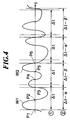
- FIG. 4 is a waveform diagram useful in explaining a manner of dynamically cutting out waveforms used as coefficients;
- FIG. 5A is a waveform diagram useful in explaining a manner of coefficient interpolation carried Out in switching from a coefficient A to a coefficient B;
- FIG. 5B is a waveform diagram useful in explaining a manner of coefficient interpolation carried out in switching from the coefficient A to a coefficient B';
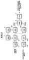
- FIG. 6 is a block diagram showing the construction of a synthesized sound generating apparatus according to another embodiment of the present invention; and
- FIG. 7 is a diagram useful in explaining a cross fade process.
-
- The present invention will be described below in detail with reference to the drawings showing preferred embodiments thereof.
- FIG. 2 is a block diagram showing the construction of a synthesized sound generating apparatus according to an embodiment of the present invention. In this embodiment, the synthesized sound generating apparatus according to the present invention is applied to a vocoder to generate a synthesized signal by dynamically cutting out waveforms from an analog speech signal (a first signal) input from a microphone or the like, to extract characteristic information therefrom to thereby generate coefficients and convoluting the generated coefficients into an analog instrumental sound signal (or a music signal (second signal) from an electric guitar, a synthesizer, or the like.
- The input analog speech signal is converted into a digital value (digital speech signal) by an AD converter 1-1. At the same time, an input analog instrumental-sound signal is converted into a digital value (digital instrumental-sound signal) by an AD converter 1-2. Outputs from the AD converters 1-1, 1-2 are processed by digital signal processors (DSP) 2-1, 2-2, respectively.
- The digital signal processor 2-1 subjects the digital speech signal from the AD converter 1-1 to sound pressure control and sound quality correction, and cuts out sound waveforms from the speech signal at predetermined time intervals of, for example, 10 to 20ms to generate coefficients h, which are transmitted to a convolution circuit (CNV) 3. The digital signal processor 2-2 subjects the digital instrumental-sound signal to sound pressure control and sound quality correction to supply the processed signal to the
convolution circuit 3 as data. - The sound pressure control by the digital signal processors 2-1, 2-2 comprises correcting and controlling, for example, the sound pressure level (dynamic range), and the sound quality correction comprises correcting the frequency characteristic. Further, the sound pressure control includes creating sound characters. Also low-frequency range noise from the microphone is cut off.
- The
convolution circuit 3 performs a convolution operation based on the coefficients h output from the digital signal processor 2-1 and the data output from the digital signal processor 2-2. The coefficients are updated at the same time intervals (cycle) as those at which the sound waveforms are cut out, that is, every 10 to 20ms. - The
convolution circuit 3 executes the convolution operation in a manner such as one shown in FIG. 3. That is, an input x(n), which is output data from the digital signal processor 2-2, is sequentially delayed by one-sample delay devices D1 to DN-1. Then, multipliers MO to MN-1 multiply the input x(n) and signals x(n-1) to x(n-N+1) obtained by delaying the input x(n), by the coefficients h(0) to h(N-1) output from the digital signal processor 2-1, respectively. Outputs from the multipliers MO to MN-1 are sequentially added together by adders A1 to AN-1, to obtain an output y(n). - Thus, the output y(n) is expressed by
Equation 1 given below: - This convolution operation is realized by a well-known FIR (finite impulse response) filter. With a small filter length, the filter acts as an equalizer to carry out a frequency characteristic-correcting function, whereas with a large filter length, the filter can execute signal processing called reverberation. In common convolution operations, the coefficients h are fixed, but in the present invention these coefficients are varied. Specifically, in the present invention waveforms of the speech signals cut out at the short time intervals as described above are used as the coefficients. The coefficients are automatically updated in response to the sequentially varying speech signal. The instrumental sound signal thus convoluted with the coefficients as described above is similar to those obtained through processing by the conventional vocoders.
- The coefficient switching cycle is preferably between 10 and 20ms for both men and women. The waveform cutting-out with a fixed cycle, however, results in clip noise or distortion in the signal, which is aurally sensed. To avoid this, the digital signal processor 2-1 obtains the coefficients h used for the convolution operation by dynamically cutting out waveforms in such a manner that each waveform starts at a zero cross point and ends at another zero cross point separated from the first one by a time interval which is close to a reference switching cycle Δt.
- For example, if the input speech signal varies as shown in FIG. 4 and when waveforms W1, W2, ... are cut out with the fixed switching cycle Δt, there is a high probability that the start and end points of each waveform do not coincide with zero cross points P1, P2, Thus, the digital signal processor 2-1 dynamically varies the cutting-out cycle. Specifically, the waveform cutting-out is executed by determining from actual waveforms, time intervals Δt-α, Δt-β, Δt-α', Δt+β', ... each corresponding to a section between two zero cross points which is close to the fixed switching cycle Δt.
- A similar technique is known from a sound waveform cutting-out device used in a speech synthesis apparatus proposed by Japanese Laid-Open Patent Publication (Kokai) No. 7-129196. The object of this patent, however, is to generate waveforms for one pitch and is not directed to the convolution coefficients for vocoders. The pitch information is not so important to the vocoder according to the present invention because it updates the coefficients through interpolation.
- Even if the dynamically cut-out coefficients are used for the convolution operation as described above, if a coefficient A has a waveform passing through zero cross points as shown in FIGS. 5A and 5B, the waveform of the actually output synthesized signal undergoes a rapid change in level when the coefficient A is instantaneously switched to the next coefficient B. This may also result in clip noise or distortion, which is aurally sensed. To avoid such a rapid change in level, the
convolution circuit 3 in FIG. 2 slowly switches from the coefficient A to the next coefficient B' by executing an interpolation over a period of time substantially equal to the cutting-out interval, as shown in FIG. 5B. This solves the noise or distortion problem. - Various interpolation operation methods may be applied to the above interpolation, among which the linear interpolation is simplest. According to the linear interpolation, if the interpolation time is denoted by c [ms], the initial coefficient value by a, and the final coefficient value by b, then the coefficient value obtained a time x = t [ms] after the start of the interpolation is
- The coefficients generated by the digital signal processor 2-1 through the above described processing are stored in a memory (RAM) 4. The coefficients are then supplied to the
convolution circuit 3 under the control of aCPU 5. An output from theconvolution circuit 3 is imparted with effects such as sound quality correction and echoes by a digital signal processing circuit 6, and is then converted back into an analog signal by a D/A converter 7 to be output as a synthesized speech signal. - FIG. 6 shows the construction of a synthesized sound generating apparatus (vocoder) according to another embodiment of the present invention. In the synthesized sound generating apparatus according to the present embodiment, two convolution circuits 3-1, 3-2 are arranged in parallel to carry out a cross fade interpolation process. That is, the two convolution circuits 3-1, 3-2 do not have such an interpolation function as is provided by the
convolution circuit 3 in FIG. 2, and are each comprised of an inexpensive LSI. - Similarly to the synthesized sound generating apparatus in FIG. 2, the AD converter 1-1 converts an input analog speech signal into a digital value (digital speech signal). At the same time, the AD converter 1-2 converts an input analog instrumental sound signal into a digital value (digital instrumental sound signal). The digital signal processor 2-1 subjects the digital speech signal from the AD converter 1-1 to sound pressure control and sound quality correction, and cuts out sound waveforms from the speech signal at predetermined time intervals of, for example, 10 to 20ms to generate the coefficients h, which are transmitted to the convolution circuits (CNV) 3-1 and 3-2. The digital signal processor 2-2 subjects the digital instrumental sound signal to sound pressure control and sound quality correction to supply the processed signal to the convolution circuits 3-1 and 3-2 as data.
- The coefficients generated by the digital signal processor 2-1 are temporarily stored in the
RAM 4. The coefficients are then supplied to the convolution circuits 3-1 and 3-2 under the control of theCPU 5. The convolution circuits 3-1 and 3-2 each execute a convolution operation based on the coefficients from the digital signal processor 2-1 and the data from the digital signal processor 2-2. Outputs from the convolution circuits 3-1, 3-2 are imparted with effects such as sound quality correction and echoes by the digital signal processing circuit 6, and are then converted back into an analog signal by the D/A converter 7 to be output as a synthesized speech signal. In the present embodiment, the digital signal processor 6 carries out a cross fade process in contrast to the configuration in FIG. 2. - The cross fade process executed by the digital signal processor 6 is shown in FIG. 7. That is, the output CNV1 from the first convolution circuit 3-1 and the output CNV2 from the second convolution circuit 3-2 are caused to partly overlap on the time axis and cross each other in such a manner that the latter half of the preceding output is faded out while the former half of the following output is simultaneously faded in, thereby reducing noise which may occur if the coefficients are instantaneously switched. For example, when the latter half B of the output CNV1 is faded out, the former half C of the output CNV2 is simultaneously faded in. Next, when the latter half D of the output CNV2 is faded out, the former half E of the next output CNV1 is simultaneously faded in. In the illustrated example, the length of the section over which the outputs CNV1 and CNV2 overlap each other is made equal to the dynamically varying switching cycle Δt, previously described with reference to FIG. 4. Therefore, the required length of each waveform cut out by the digital signal processor 2-1 in FIG. 6 is essentially twice or more as large as that in the configuration in FIG. 2.
Claims (11)
- A synthesized sound generating apparatus comprising:a coefficient generating means for generating coefficients by using dynamic cutting to extract characteristic information from a first signal; anda synthesized signal generating means for carrying out a convolution operation on a second signal using the coefficients generated by said coefficient generating means to generate a synthesized signal.
- A synthesized signal generating apparatus according to claim 1, wherein said synthesized signal generating means comprises a convolution circuit that carries out an interpolation process on said coefficients to prevent a rapid change in level of the generated synthesized signal upon switching of said coefficients.
- A synthesized signal generating apparatus according to claim 1, wherein said first signal is a speech signal, and said characteristic information extracted from said speech signal indicates one waveform starting at a zero cross point and ending at another zero cross point separated from said zero cross point by a time interval close to a reference switching cycle.
- A synthesized signal generating apparatus according to claim 3, wherein said time interval is determined from an actual waveform of said speech signal.
- A synthesized signal generating apparatus according to claim 3, wherein said second signal is an instrumental sound signal.
- A synthesized signal generating apparatus comprising:a coefficient generating means for dynamically continuously cutting out waveforms from a first signal in a manner such that adjacent ones of the waveforms cut out from the first signal partly overlap each other, to extract characteristic information therefrom to generate coefficients;a convolution means for alternately receiving said coefficients generated from said waveforms continuously cut out by said coefficient generating means and carrying out convolution operations on a second signal using the coefficients to generate a first synthesized signal and a second synthesized signal, respectively; anda cross fade processing means for carrying out a cross fade process on said first synthesized signal and said second synthesized signal generated by said convolution means, upon switching of said coefficients.
- A synthesized signal generating apparatus according to claim 6, wherein wherein said first signal is a speech signal, and said characteristic information extracted from said speech signal indicates one waveform starting at a zero cross point and ending at another zero cross point separated from said zero cross point by a time interval close to a reference switching cycle.
- A synthesized signal generating apparatus according to claim 6, wherein said time interval is determined from an actual waveform of said speech signal.
- A synthesized signal generating apparatus according to claim 7, wherein said second signal is an instrumental sound signal.
- A synthesized sound generating method comprising:a coefficient generating step of generating coefficients by using dynamic cutting to extract characteristic information from a first signal; anda synthesized signal generating step of carrying out a convolution operation on a second signal using the coefficients generated by said coefficient generating step to generate a synthesized signal.
- A synthesized signal generating method comprising:a coefficient generating step of dynamically continuously cuts out waveforms from a first signal in a manner such that adjacent ones of the waveforms cut out from the first signal partly overlap each other, to extract characteristic information therefrom to generate coefficients;a convolution step of alternately receiving said coefficients generated from said waveforms continuously cut out by said coefficient generating step and carrying out convolution operations on a second signal using the coefficients to generate a first synthesized signal and a second synthesized signal; anda cross fade processing step of carrying out a cross fade process on said first synthesized signal and said second synthesized signal generated by said convolution step, upon switching of said coefficients.
Applications Claiming Priority (2)
| Application Number | Priority Date | Filing Date | Title |
|---|---|---|---|
| JP22280999A JP3430985B2 (en) | 1999-08-05 | 1999-08-05 | Synthetic sound generator |
| JP22280999 | 1999-08-05 |
Publications (2)
| Publication Number | Publication Date |
|---|---|
| EP1074968A1 true EP1074968A1 (en) | 2001-02-07 |
| EP1074968B1 EP1074968B1 (en) | 2006-11-15 |
Family
ID=16788249
Family Applications (1)
| Application Number | Title | Priority Date | Filing Date |
|---|---|---|---|
| EP00116813A Expired - Lifetime EP1074968B1 (en) | 1999-08-05 | 2000-08-03 | Synthesized sound generating apparatus and method |
Country Status (4)
| Country | Link |
|---|---|
| US (1) | US6513007B1 (en) |
| EP (1) | EP1074968B1 (en) |
| JP (1) | JP3430985B2 (en) |
| DE (1) | DE60031812T2 (en) |
Families Citing this family (17)
| Publication number | Priority date | Publication date | Assignee | Title |
|---|---|---|---|---|
| JP2001356800A (en) * | 2000-06-16 | 2001-12-26 | Korg Inc | Formant addition device |
| JP2002221980A (en) * | 2001-01-25 | 2002-08-09 | Oki Electric Ind Co Ltd | Text voice converter |
| JP3709817B2 (en) * | 2001-09-03 | 2005-10-26 | ヤマハ株式会社 | Speech synthesis apparatus, method, and program |
| US7433097B2 (en) * | 2003-04-18 | 2008-10-07 | Hewlett-Packard Development Company, L.P. | Optical image scanner with moveable calibration target |
| JP4179268B2 (en) * | 2004-11-25 | 2008-11-12 | カシオ計算機株式会社 | Data synthesis apparatus and data synthesis processing program |
| US8311840B2 (en) * | 2005-06-28 | 2012-11-13 | Qnx Software Systems Limited | Frequency extension of harmonic signals |
| US7912729B2 (en) | 2007-02-23 | 2011-03-22 | Qnx Software Systems Co. | High-frequency bandwidth extension in the time domain |
| JP2009128559A (en) * | 2007-11-22 | 2009-06-11 | Casio Comput Co Ltd | Reverberation effect adding device |
| JP5354485B2 (en) * | 2007-12-28 | 2013-11-27 | 公立大学法人広島市立大学 | Speech support method |
| JP5115818B2 (en) * | 2008-10-10 | 2013-01-09 | 国立大学法人九州大学 | Speech signal enhancement device |
| US8750530B2 (en) | 2009-09-15 | 2014-06-10 | Native Instruments Gmbh | Method and arrangement for processing audio data, and a corresponding corresponding computer-readable storage medium |
| DE102009029615B4 (en) * | 2009-09-18 | 2018-03-29 | Native Instruments Gmbh | Method and arrangement for processing audio data and a corresponding computer program and a corresponding computer-readable storage medium |
| JP6019803B2 (en) * | 2012-06-26 | 2016-11-02 | ヤマハ株式会社 | Automatic performance device and program |
| JP6390130B2 (en) * | 2014-03-19 | 2018-09-19 | カシオ計算機株式会社 | Music performance apparatus, music performance method and program |
| JP2016135346A (en) * | 2016-04-27 | 2016-07-28 | 株式会社三共 | Game machine |
| JP6267757B2 (en) * | 2016-08-10 | 2018-01-24 | 株式会社三共 | Game machine |
| CN114648974B (en) * | 2020-12-17 | 2025-02-18 | 南京理工大学 | Speech synthesis method and system based on speech radar and deep learning |
Citations (5)
| Publication number | Priority date | Publication date | Assignee | Title |
|---|---|---|---|---|
| US4907484A (en) * | 1986-11-02 | 1990-03-13 | Yamaha Corporation | Tone signal processing device using a digital filter |
| US5111727A (en) * | 1990-01-05 | 1992-05-12 | E-Mu Systems, Inc. | Digital sampling instrument for digital audio data |
| US5247130A (en) * | 1990-07-24 | 1993-09-21 | Yamaha Corporation | Tone signal processing apparatus employing a digital filter having improved signal delay loop |
| US5250748A (en) * | 1986-12-30 | 1993-10-05 | Yamaha Corporation | Tone signal generation device employing a digital filter |
| US5744742A (en) * | 1995-11-07 | 1998-04-28 | Euphonics, Incorporated | Parametric signal modeling musical synthesizer |
Family Cites Families (8)
| Publication number | Priority date | Publication date | Assignee | Title |
|---|---|---|---|---|
| US3624301A (en) * | 1970-04-15 | 1971-11-30 | Magnavox Co | Speech synthesizer utilizing stored phonemes |
| JPS5681900A (en) * | 1979-12-10 | 1981-07-04 | Nippon Electric Co | Voice synthesizer |
| FR2678103B1 (en) * | 1991-06-18 | 1996-10-25 | Sextant Avionique | VOICE SYNTHESIS PROCESS. |
| JPH05204397A (en) | 1991-09-03 | 1993-08-13 | Yamaha Corp | Voice analyzing and synthesizing device |
| US5864812A (en) * | 1994-12-06 | 1999-01-26 | Matsushita Electric Industrial Co., Ltd. | Speech synthesizing method and apparatus for combining natural speech segments and synthesized speech segments |
| JP3046213B2 (en) * | 1995-02-02 | 2000-05-29 | 三菱電機株式会社 | Sub-band audio signal synthesizer |
| US6073100A (en) * | 1997-03-31 | 2000-06-06 | Goodridge, Jr.; Alan G | Method and apparatus for synthesizing signals using transform-domain match-output extension |
| US6253182B1 (en) * | 1998-11-24 | 2001-06-26 | Microsoft Corporation | Method and apparatus for speech synthesis with efficient spectral smoothing |
-
1999
- 1999-08-05 JP JP22280999A patent/JP3430985B2/en not_active Expired - Fee Related
-
2000
- 2000-07-20 US US09/619,955 patent/US6513007B1/en not_active Expired - Fee Related
- 2000-08-03 DE DE60031812T patent/DE60031812T2/en not_active Expired - Lifetime
- 2000-08-03 EP EP00116813A patent/EP1074968B1/en not_active Expired - Lifetime
Patent Citations (5)
| Publication number | Priority date | Publication date | Assignee | Title |
|---|---|---|---|---|
| US4907484A (en) * | 1986-11-02 | 1990-03-13 | Yamaha Corporation | Tone signal processing device using a digital filter |
| US5250748A (en) * | 1986-12-30 | 1993-10-05 | Yamaha Corporation | Tone signal generation device employing a digital filter |
| US5111727A (en) * | 1990-01-05 | 1992-05-12 | E-Mu Systems, Inc. | Digital sampling instrument for digital audio data |
| US5247130A (en) * | 1990-07-24 | 1993-09-21 | Yamaha Corporation | Tone signal processing apparatus employing a digital filter having improved signal delay loop |
| US5744742A (en) * | 1995-11-07 | 1998-04-28 | Euphonics, Incorporated | Parametric signal modeling musical synthesizer |
Also Published As
| Publication number | Publication date |
|---|---|
| EP1074968B1 (en) | 2006-11-15 |
| DE60031812T2 (en) | 2007-09-13 |
| JP3430985B2 (en) | 2003-07-28 |
| US6513007B1 (en) | 2003-01-28 |
| DE60031812D1 (en) | 2006-12-28 |
| JP2001051687A (en) | 2001-02-23 |
Similar Documents
| Publication | Publication Date | Title |
|---|---|---|
| EP1074968B1 (en) | Synthesized sound generating apparatus and method | |
| Kawahara | Speech representation and transformation using adaptive interpolation of weighted spectrum: vocoder revisited | |
| JP4624552B2 (en) | Broadband language synthesis from narrowband language signals | |
| US4066842A (en) | Method and apparatus for cancelling room reverberation and noise pickup | |
| US8229738B2 (en) | Method for differentiated digital voice and music processing, noise filtering, creation of special effects and device for carrying out said method | |
| JP3601074B2 (en) | Signal processing method and signal processing device | |
| JP4170217B2 (en) | Pitch waveform signal generation apparatus, pitch waveform signal generation method and program | |
| EP3296992B1 (en) | Apparatus and method for modifying a parameterized representation | |
| US20040122662A1 (en) | High quality time-scaling and pitch-scaling of audio signals | |
| JPH10124088A (en) | Voice bandwidth extension apparatus and method | |
| EP0688010A1 (en) | Speech synthesis method and speech synthesizer | |
| KR20170125058A (en) | Apparatus and method for processing an audio signal to obtain processed audio signals using a target time domain envelope | |
| JPH09127996A (en) | Audio decoding method and apparatus | |
| JP4076887B2 (en) | Vocoder device | |
| WO2001097212A1 (en) | Frequency interpolating device and frequency interpolating method | |
| Keiler et al. | Efficient linear prediction for digital audio effects | |
| JP3901475B2 (en) | Signal coupling device, signal coupling method and program | |
| JP3197975B2 (en) | Pitch control method and device | |
| JP3749838B2 (en) | Acoustic signal encoding method, acoustic signal decoding method, these devices, these programs, and recording medium thereof | |
| JPH0318720B2 (en) | ||
| JP3192999B2 (en) | Voice coding method and voice coding method | |
| JP3233543B2 (en) | Method and apparatus for extracting impulse drive point and pitch waveform | |
| JP2615856B2 (en) | Speech synthesis method and apparatus | |
| JP2009237590A (en) | Vocal effect-providing device | |
| JP3063088B2 (en) | Speech analysis and synthesis device, speech analysis device and speech synthesis device |
Legal Events
| Date | Code | Title | Description |
|---|---|---|---|
| PUAI | Public reference made under article 153(3) epc to a published international application that has entered the european phase |
Free format text: ORIGINAL CODE: 0009012 |
|
| AK | Designated contracting states |
Kind code of ref document: A1 Designated state(s): DE GB |
|
| AX | Request for extension of the european patent |
Free format text: AL;LT;LV;MK;RO;SI |
|
| 17P | Request for examination filed |
Effective date: 20010711 |
|
| AKX | Designation fees paid |
Free format text: DE GB |
|
| 17Q | First examination report despatched |
Effective date: 20041028 |
|
| GRAP | Despatch of communication of intention to grant a patent |
Free format text: ORIGINAL CODE: EPIDOSNIGR1 |
|
| GRAS | Grant fee paid |
Free format text: ORIGINAL CODE: EPIDOSNIGR3 |
|
| GRAA | (expected) grant |
Free format text: ORIGINAL CODE: 0009210 |
|
| AK | Designated contracting states |
Kind code of ref document: B1 Designated state(s): DE GB |
|
| REG | Reference to a national code |
Ref country code: GB Ref legal event code: FG4D |
|
| REF | Corresponds to: |
Ref document number: 60031812 Country of ref document: DE Date of ref document: 20061228 Kind code of ref document: P |
|
| RAP2 | Party data changed (patent owner data changed or rights of a patent transferred) |
Owner name: YAMAHA CORPORATION |
|
| PLBE | No opposition filed within time limit |
Free format text: ORIGINAL CODE: 0009261 |
|
| STAA | Information on the status of an ep patent application or granted ep patent |
Free format text: STATUS: NO OPPOSITION FILED WITHIN TIME LIMIT |
|
| 26N | No opposition filed |
Effective date: 20070817 |
|
| PGFP | Annual fee paid to national office [announced via postgrant information from national office to epo] |
Ref country code: DE Payment date: 20090730 Year of fee payment: 10 Ref country code: GB Payment date: 20090729 Year of fee payment: 10 |
|
| GBPC | Gb: european patent ceased through non-payment of renewal fee |
Effective date: 20100803 |
|
| REG | Reference to a national code |
Ref country code: DE Ref legal event code: R119 Ref document number: 60031812 Country of ref document: DE Effective date: 20110301 |
|
| PG25 | Lapsed in a contracting state [announced via postgrant information from national office to epo] |
Ref country code: DE Free format text: LAPSE BECAUSE OF NON-PAYMENT OF DUE FEES Effective date: 20110301 |
|
| PG25 | Lapsed in a contracting state [announced via postgrant information from national office to epo] |
Ref country code: GB Free format text: LAPSE BECAUSE OF NON-PAYMENT OF DUE FEES Effective date: 20100803 |