EP1074880A1 - Camera having light-blocking label - Google Patents
Camera having light-blocking label Download PDFInfo
- Publication number
- EP1074880A1 EP1074880A1 EP00202523A EP00202523A EP1074880A1 EP 1074880 A1 EP1074880 A1 EP 1074880A1 EP 00202523 A EP00202523 A EP 00202523A EP 00202523 A EP00202523 A EP 00202523A EP 1074880 A1 EP1074880 A1 EP 1074880A1
- Authority
- EP
- European Patent Office
- Prior art keywords
- label
- camera
- casing
- obstruction
- film
- Prior art date
- Legal status (The legal status is an assumption and is not a legal conclusion. Google has not performed a legal analysis and makes no representation as to the accuracy of the status listed.)
- Withdrawn
Links
- 239000000463 material Substances 0.000 abstract description 12
- 239000004033 plastic Substances 0.000 description 14
- 229920003023 plastic Polymers 0.000 description 14
- 238000003491 array Methods 0.000 description 4
- 230000000694 effects Effects 0.000 description 4
- 238000000034 method Methods 0.000 description 4
- 238000013461 design Methods 0.000 description 3
- 239000010410 layer Substances 0.000 description 3
- 238000004519 manufacturing process Methods 0.000 description 3
- 239000000203 mixture Substances 0.000 description 3
- 239000007787 solid Substances 0.000 description 3
- 239000004793 Polystyrene Substances 0.000 description 2
- 229920006364 Rulon (plastic) Polymers 0.000 description 2
- 239000000853 adhesive Substances 0.000 description 2
- 230000001070 adhesive effect Effects 0.000 description 2
- 238000005452 bending Methods 0.000 description 2
- 238000005266 casting Methods 0.000 description 2
- 230000015556 catabolic process Effects 0.000 description 2
- 238000006731 degradation reaction Methods 0.000 description 2
- 230000000994 depressogenic effect Effects 0.000 description 2
- 239000011888 foil Substances 0.000 description 2
- 238000001746 injection moulding Methods 0.000 description 2
- 238000002372 labelling Methods 0.000 description 2
- 230000007246 mechanism Effects 0.000 description 2
- 230000004048 modification Effects 0.000 description 2
- 238000012986 modification Methods 0.000 description 2
- 229920002223 polystyrene Polymers 0.000 description 2
- 239000012858 resilient material Substances 0.000 description 2
- 239000004698 Polyethylene Substances 0.000 description 1
- 239000012790 adhesive layer Substances 0.000 description 1
- 238000013459 approach Methods 0.000 description 1
- 230000008901 benefit Effects 0.000 description 1
- 230000005540 biological transmission Effects 0.000 description 1
- 230000008859 change Effects 0.000 description 1
- 230000007423 decrease Effects 0.000 description 1
- 230000002939 deleterious effect Effects 0.000 description 1
- 239000002184 metal Substances 0.000 description 1
- 239000002991 molded plastic Substances 0.000 description 1
- 230000007935 neutral effect Effects 0.000 description 1
- 230000002093 peripheral effect Effects 0.000 description 1
- RGCLLPNLLBQHPF-HJWRWDBZSA-N phosphamidon Chemical compound CCN(CC)C(=O)C(\Cl)=C(/C)OP(=O)(OC)OC RGCLLPNLLBQHPF-HJWRWDBZSA-N 0.000 description 1
- -1 polyethylene Polymers 0.000 description 1
- 229920000573 polyethylene Polymers 0.000 description 1
- 230000008569 process Effects 0.000 description 1
- 238000012545 processing Methods 0.000 description 1
- 230000009467 reduction Effects 0.000 description 1
- 238000000926 separation method Methods 0.000 description 1
- 229920002379 silicone rubber Polymers 0.000 description 1
- 238000011144 upstream manufacturing Methods 0.000 description 1
- 230000037303 wrinkles Effects 0.000 description 1
Images






Classifications
-
- G—PHYSICS
- G03—PHOTOGRAPHY; CINEMATOGRAPHY; ANALOGOUS TECHNIQUES USING WAVES OTHER THAN OPTICAL WAVES; ELECTROGRAPHY; HOLOGRAPHY
- G03B—APPARATUS OR ARRANGEMENTS FOR TAKING PHOTOGRAPHS OR FOR PROJECTING OR VIEWING THEM; APPARATUS OR ARRANGEMENTS EMPLOYING ANALOGOUS TECHNIQUES USING WAVES OTHER THAN OPTICAL WAVES; ACCESSORIES THEREFOR
- G03B19/00—Cameras
- G03B19/02—Still-picture cameras
- G03B19/04—Roll-film cameras
Definitions
- the invention relates to photography and to cameras and more particularly relates to a camera having a light-blocking label.
- the casing of a camera provides physical support for internal components and keeps out incidental light.
- Plastic casings were, at one time, very thick in order to provide adequate structural strength. Passage of incidental light through the material of the casing was not possible. In recent years, adequate strength has been provided by thin, injection-molded plastic casings. Dimensions of these casings can be reduced to the point that the composition of the plastic used must be highly opaque in order to adequately block light entry. Further reductions in dimensions or use of less opaque materials have not been warranted, since the resulting casing would have translucent regions.
- U.S. Patent No. 5,472,543 entitled Method for Label Application Using Bernoulli Effect discloses a labeling method in which a label is floated on an air cushion into a substantially exact alignment with an area of an item receiving the label. It has been determined that the accuracy of the label placement provided by this method is very great.
- a camera having a light transmissive region, such as a region of translucent plastic, and a label precisely placed to block the passage of light through the transmissive region.
- the invention in its broader aspects, provides a camera that has a casing enclosing a film area.
- the casing has a stray light path into the film area due to a light transmissive region, such as a region of translucent material.
- the light transmissive region can be bounded by an obstruction to label placement.
- a label is adhered to the casing.
- the label has an opaque portion covering the transmissive region.
- the label can be aligned with an obstruction boundary and spaced from the obstruction boundary by 0.6 mm or less. It is an advantageous effect of at least some of the embodiments of
- a camera that has a light transmissive region, such as a region of translucent plastic, and a label precisely placed to block the passage of light through the transmissive region.
- a camera 100 has a casing 112 that encloses a film area 114.
- the casing 112 has one or more light-transmissive regions 116 that define undesired stray light paths into the film area 114.
- the casing 112 also has opaque regions 118 that block admission of light into the film area 114.
- a label 120 is adhered to the casing 112.
- the label 120 has an opaque portion 122 that is superimposed on the light-transmissive region 116 and blocks transmission of light through the light-transmissive region 116 of the casing 112.
- the light-transmissive regions 116 can be holes or gaps 124 in the casing 112, but it is preferred that the light-transmissive regions 116 are solid parts of the casing 112.
- the casing 112 of the camera 100 includes a frame 126 and front and rear covers 128,130 joined over the frame 126.
- the casing 112 has interior and exterior surfaces 129,131.
- the invention is generally described herein in relation to a camera 100 having a single label 120 adhered to an exterior surface 131, but it will be understood that a label 120 can be on an interior surface 129 and multiple labels 120 can be used.
- a single label 120 mounted to an exterior surface 131 is preferred for ease of manufacturing.
- the film area 114 includes an exposure chamber 134 to which light is directed by a taking lens 136 for picture taking. Within the casing 112, in the film area 114, unexposed film 132 is moved from a first film chamber 138, across the exposure chamber 134, to a second film chamber 140.
- the type of film and manner of film transport is not critical. For example, a one or two chamber film cartridge or a cartridgeless film roll can be used. Film can be prewind and be returned to a film cartridge at the time of film exposure, or rewinding after exposure can be required.
- the embodiment illustrated in the figures is a one-time use camera 100, in which a film roll 142 housed in an otherwise empty film supply chamber 138, is moved by a film transport (indicated schematically by box 144) across the exposure chamber 134 to a film cartridge 145 housed in a film cartridge chamber 140.
- the exposure chamber 134 is between the opposed film chambers 140,142 and has a baffle through which light is admitted from the taking lens 136 when film exposures are made.
- the chambers 134,138,140 are parts of the frame 126.
- Joined to the frame 126 are various camera components 147 (illustrated by boxes in Figure 2) that, together with the frame 126, comprise a frame assembly 146.
- Examples of such components include a viewfinder, a flash unit, an shutter mechanism, and the film transport 144.
- the components 147 include appropriate control features that extend through the casing 112.
- the shutter mechanism includes a shutter button.
- the film transport 144 includes a thumbwheel or advance lever. Suitable components and other features of the camera 100 that are not illustrated, are well known to those of skill in the art.
- the light transmissive region 116 is an opening 116a between the front and rear covers 128,130, in which a screwdriver or other tool can be inserted when the camera 100 is opened for film processing. It is preferred that the camera 100 not have such openings that could admit light to the film area 114, since foreign objects could penetrate the label 120 at an opening and damage the interior of the camera 100 or allow light leakage. It is preferred that any and all light-transmissive regions 116 of the casing 112 be free of openings 116a. Preferred light-transmissive regions 116 of the casing 112 are regions 116b of solid translucent plastic.
- translucent is used herein in a technical sense, to describe a medium which transmits rays of light so diffused that objects cannot be seen distinctly.
- plastics used for one-time use camera bodies such as polystyrene
- Labels 120 are thinner and less resistant to such deformation. It is preferred for convenience in production that the label 120 is very thin relative to the casing 112 and compliant, but resistant to punctures.
- An example of a suitable label 120 material is a polymeric blend of polystyrene and polyethylene. Even if abused, such a label 120 is unlikely to admit light and spoil the film 132. There is a risk, however, that an intruding object could bend the label 120 and cause pressure marks on the film 132. This risk is not present when the only transmissive regions 116 on a camera 100 are regions 116b of solid, translucent plastic.
- Single or multiple light-transmissive regions 116 can be present on the casing 112. All of the light-transmissive regions 116 can be covered by a single label 120 or multiple labels 120 can be used. For convenience, the invention is generally discussed herein in relation to a camera 100 having a single translucent region 116b covered by a single label 120.
- the rear cover 130 includes translucent region 116b and opaque regions 118.
- the opaque regions 118 do not allow light to pass through.
- the translucent region 116b is thinner than the opaque regions 118 and is continuous with the opaque regions 118.
- the cover portions 128,130 are each preferably a one-piece plastic casting produced by injection molding or the like.
- the translucent region 116b can differ in opacity from the opaque regions 118 on the basis of a difference in composition rather than a difference in thickness; but this is not preferred, since this approach does not provide an advantage of reduced size.
- the rear cover 130 closes the chambers 134,138,140.
- the rear cover 130 of the camera 100 is preferably a one-piece plastic casting produced by injection molding or similar process.
- the rear cover 130 is composed of a material that has a uniform opacity per unit volume, but the part of the rear cover 130 that forms the translucent region 16b is sufficiently thin as to be translucent and transmit light.
- the rear cover 130 can be neutral in color or can have a hue, in which case, the transmitted light will be colored.
- Opaque regions 118 and translucent regions 116b are continuous with each other, but the translucent regions 116b are thinner.
- the translucent region 116b is shown as overlapping the exposure chamber 134 and film supply chamber 138.
- the translucent region 116b can be of different sizes and in different positions as required by a particular camera 100 design. In the camera 100 design shown, the reduced thickness at the translucent region 116b decreases contact of the film 132 with the back cover 130.
- the back cover 130 can have one or more longitudinal ribs or other protrusions. (Ribs are illustrated in Figure 2 by a dashed line 148.) The ribs or protrusions act as a platen for the film 132 in the exposure chamber 134.
- the back cover 130 can be convoluted to provide the ribs. In that case the ribs can be translucent. Alternatively, the ribs can be provided as an array of thickened opaque regions 118 interposed in an interrupted translucent region 116b.
- the label 120 is adhered to the casing 112. In the embodiment shown in the figures, the label 120 is adhered to the rear cover 130 and to the front cover 128. The label 120 is shown folded over an edge 149. The label 120 is preferably compliant to allow such folding without creasing and to allow easy placement on curved surfaces.
- the opaque portion 122 of the label 120 covers the translucent region 116b.
- the opacity of the label 120 can be provided in a variety of different ways. Referring to Figure 3, a convenient way of providing opacity is the use of a multiple layer label 120, in which one of the layers is metallized plastic or metallic foil. In Figure 3 an adhesive layer 150 is bonded to a layer 152 of foil or metallized plastic, to which is bonded a layer 154 of printable material such as paper or printable plastic. Such labels are inexpensive and are well known to those of skill in the art.
- the opaque portion 122 of the label 120 can encompass the entire label or can be limited to only the part of the label 120 overlying the translucent portion 116b of the casing 112. This is largely a matter of artistic design. For example, if the casing 112 of the camera 100 is colored, the label 120 can have one or more transparent areas to shown the color of the casing 112.
- the camera 100 has obstructions 156 that extend inward or outward relative to the rest of the camera casing 112 or otherwise present a discontinuity or obstruction 156 in the casing 112.
- the obstructions 156 cannot be covered by label 120 without degradation of the function or appearance of the camera or both. In some embodiments such as the one shown in Figure 1, covering the obstructions 156 partially or completely with the label 120 would also present a risk of light leakage to the translucent region 116b of the casing 112.
- Many obstructions 156 are control elements 158; such as the viewfinder 158a, the thumbwheel 158b, and the shutter button 158c shown in Figure 1; that must be accessible to the user for picture taking.
- a control element 158 is considered an obstructions 156, if it must remain uncovered or presents sufficient surface relief to hinder label placement.
- Other obstructions 156 such as the grip elements 160 shown in Figure 1 could receive a label 120; but not without degradation of function.
- the grip elements 160 are small structures that help the user hold the camera 100.
- Still other obstructions are interference features that abruptly change camera contours and for that reason cannot be cleanly labeled.
- the viewfinder 158a and grip elements 160 are the only obstructions 156 discussed, since the other obstructions 156 are spaced from the label 120.
- Adjoining the obstructions 156 are obstruction boundaries 162, parts of the casing 112 that define limits of the area that can be covered by a label 120. On the casing 112, the obstruction boundaries 162 define limits of the area that can receive a label 120. It is highly preferred that obstruction boundaries 162 of the casing 112 are part of an opaque region 118 rather than the translucent region 116b. Obstruction boundaries 162 on the translucent region 116b present a risk of light piping. The obstruction boundaries 162 receive the label 120, without deleterious effect. Depending upon the position of the obstruction 156 on the camera casing 112, the obstruction boundary 162 can surround all or part of the obstruction 156.
- the label 120 is adhered to the casing 112 in registration with the obstruction boundaries 162.
- edges of the label 120 overlap and are coextensive with obstruction boundaries 162 for that obstruction 156. This assures good contact of the label 120 with the casing 112.
- the translucent region can closely adjoin an obstruction 156, yet still be rendered opaque by the label 120.
- the obstruction boundary 162 can be covered by an outer edge of the label 120, as is the case in Figure 1, with the obstruction boundary 162a around the viewfinder.
- the obstruction boundary 162 can be covered by an inner edge of the label 120, as is the case in Figure 1 with the obstruction boundaries 162 around each of the grip elements 160.
- the label 120 is adhered to the casing 112 in registration with the obstruction boundaries 162 such that the label 120 is aligned with the translucent region and the obstruction boundary 162 translationally is within 0.6 mm, that is, the tolerance for the location for each edge of the label 120 is ⁇ 0.3 mm. It is more preferred that the obstruction boundary 162 translationally is within 0.4 mm of the label edge (a tolerance of ⁇ 0.2 mm) and still more preferred within 0.2 mm (a tolerance of ⁇ 0.1). This precise positioning of the label 120 protects against light leakage through the transmissive region 116, despite close placement of the transmissive region 116 and the obstruction boundaries 162.
- the obstruction boundary 162 can border the transmissive region 116 on one or more sides and can even surround the transmissive region 116.
- the obstruction 156 is a grip element 164 in the shape of an indicia, shown in Figures 4-5 as the letter "K".
- the labels 120 can be attached within 0.6 mm of obstruction boundaries 162 using the Bernoulli effect labeler heads 48, labeling apparatus 10, and methods disclosed in U.S. Patent No. 5,472,543. Separations of 0.4 mm or less and 0.2 mm or less can be provided by careful tolerancing of all manufacturing components or by culling of cameras with the greatest variance, or both.
- the labeler head 48 comprises a main member 50 having a support surface 52 which may be flat, or convex and substantially cylindrical with an axis of curvature.
- a plenum 54 within the main member 50 communicates with a plurality of bores 56 extending from the plenum 54 through the support surface 52.
- the bores 56 are angled with respect to the support surface 52 and arranged in an array so that jets of gas issuing from the array will cause a label 120 to be drawn onto the support surface 52 when the label 120 is presented to the support surface 52 and a first side of the label 120 is brought into close proximity of the jets, thereby causing a zone of reduced gas pressure to be formed between the support surface and the first side of the label and establishing a pressure differential across the label 120 to hold the label 120 on a film of gas flowing over the support surface 52.
- a gas supply (not shown) provides a flow of gas into the plenum 54 and through the angled bores 56. The gas supply provides pulses of higher pressure gas to propel labels 120 against the camera casing 112 to be labeled and can provide a vacuum to the labeler head 48 as necessary to hold label 120.
- an elongated carrier strip 12 has a surface having low affinity for the adhesive-backed side of a plurality of pressure-sensitive labels 120. Display sides of the labels face outward from the carrier strip 12. Labels 120 can be of practically any shape and are moderately stiff, to facilitate ready removal from the carrier strip 12.
- the carrier strip is wound in a large roll 24 prior to label removal.
- the used carrier strip 12, depleted of labels 120, is likewise wound in a roll 26.
- the rolls 24,26 are mounted to the apparatus 10 for rotation such that strip 12 is pulled around an idler roller 20 and then around the edge of a peeler plate 22.
- the labels release gradually and automatically from strip 12 as the strip passes around the edge of the peeler plate 22 and are presented substantially tangentially to the labeler head 48.
- the labeler head 48 is reciprocated in directions indicated by double-headed arrow 28 by a drive 29.
- the casing 112 is supported on a bracing or conveyor 30. A nest can be used to support the casing 112.
- the main member 50 of the labeler head 48 is a material such as metal or rigid plastic or a resilient material.
- the support surface 52 is smooth and typically flat.
- a plenum 54 communicates with a plurality of bores 56 which extend from plenum 54 to support surface 52.
- bores 56 have a diameter in the range of 0.012 to 0.032 inch (0.030 to 0.081 cm) and are set at an angle to support surface 52 in the range of 5 to 45 degrees.
- a port 58 is provided through main member 50 to connect plenum 54 to the gas supply to provide pressurized air or subatmospheric pressure.
- Bores 56 are arranged in an array so that jets of gas issuing from the bores will cause label 120 to be drawn onto support surface 52 when the label 120 is presented to the support surface and its display side is brought into close proximity with the jets of gas.
- the flow of gas causes a zone of reduced gas pressure to be formed between support surface 52 and label 120, in accordance with the Bernoulli Effect, thereby establishing a pressure differential across the label 120 to hold the label 120 in position on a film of gas flowing over the support surface.
- the array is also configured so that, once released, label 120 will move relative to support surface 52 and reposition itself accurately against one or more stops 60 provided on or adjacent the support surface.
- label 120 covers the portion of the array of bores 56 which are at least partially directed toward stops 60, when the label 120 is positioned against the stops.
- Stops 60 can be supported on resilient springs 61, which allow the stops to be depressed to the level of support surface 52 during label 120 application.
- stops 60 are made from a material to which the adhesive of the labels 120 will not stick readily, such as Rulon, a plastic material made by Dixon Industries Corp. of Bristol, R.I. U.S.A.
- Figures 8-9 illustrate another labeler head 48 useful with the apparatus 10, in which flat support surface 52 is replaced by a resilient insert 62 of a material such as silicon rubber which has cylindrical, convex support surface 64 having an axis of curvature transverse to the direction from which label 120 is fed to labeler head 48.
- a pair of stop pins or abutments 66 are provided on one side of support surface 64. Stop pins 66 preferably also are made from a non-stick material such as Rulon.
- at least a portion of bores 56 are angled so that their jets of gas are directed at least partially toward stop pins 66 and do not oppose movement of label 120 onto the labeler head.
- the jets from bores 56 preferably are symmetrically placed on either side of the path of the label 120 onto the labeler head. Round labels 120 upon release will move across support surface 64 into accurate engagement with stop pins 66.
- the label 120 may be provided with a radially inwardly or outwardly extending feature which is engaged by the stop pins 66.
- the label 120 may have a central aperture; and the main member 50 may have a locator pin (not illustrated in this embodiment) positioned centrally of the array, the pin being sized to pass through the aperture of the label 120 and preferably being retractable.
- Non-symmetric arrays of bores are also useful, for example, with rectangular labels 120.
- the resilient material of insert 62 and the cylindrical shape of support surface 64 ensure that when the labeler head is pressed against a casing 112 to apply label 120, essentially line contact is first established due to the cylindrical shape and then the insert compresses, so that the label 120 is smoothly applied without bubbles or wrinkles.
- Figure 10 shows a modification of the labeler head of Figures 8-9.
- a second plenum 55 communicates with one or more bores 57 which extend from plenum 55 to support surface 64.
- Such a second plenum 55 and bores 57 also may be included in the other labeler heads discussed.
- a port 59 is provided from plenum 55 to a source of pressurized air; so that, a blast of air through bores 57 may be used to blow the label 120 onto the casing 112 to be labeled.
- Figures 11-12 illustrate typical arrays of bores 56 for labeler heads 48 of Figures 6-10, having flat support surfaces 52 approximately 0.6 and 1.0 inch (1.52 and 2.54 cm), respectively, in width ("W" in Figures 14-15).
- the number of bores depends upon the area and weight of the label 120.
- the arrows indicate the direction of the jets from bores 56 toward stops 60, preferably so that no vector component of any jet will oppose movement of label 120 onto support surface 52.
- the jets preferably are symmetrically placed relative to the path of the label 120. Thus, round labels 120 upon release will move across support surface 52 into accurate engagement with stops 60. Similar arrays of bores may be used for labels 120 of other shapes.
- Figures 13-16 illustrate another labeler head 48 which is suited for applying labels 120 having a central hole 108 and a radially inwardly extending feature such as a notch 70 extending over an arc of the circumference of the label 120.
- main member 50 is provided with a centrally positioned, tapered locator pin 72 which extends from support surface 52.
- the diameter of locator pin 72 preferably is only slightly smaller than that of central hole 108, to accurately center the label 120 on the labeler head 48.
- Surrounding locator pin 72 is an array of angled bores 74 whose jets extend in generally the same sense or circular direction about locator pin 72.
- label 120 When label 120 is released so that locator pin 72 enters hole 108, the label 120 will move down onto and spin around locator pin 72 until notch 70 settles over an axially extending stop or abutment 76, thereby stopping movement of the label 120 and accurately centering and angularly positioning it for application.
- label 120 covers the portion of the array of bores 74 which are at least partially directed toward stop 76, when the label 120 is positioned against the stop.
- the circumferential edge of the label 120 is not subjected to air flows which could dislodge it from its position against the stop.
- abutment 76 is retractable during application of the label 120, (not illustrated).
- main member 50 has a central stepped passage, which is surrounded by plenum 54, and in which locator pin 72 is slidably mounted.
- a head 80 on the locator pin is pressed against by a spring 82; so that, locator pin 72 is retractable but is biased to extend beyond support surface 52 as illustrated.
- the retractability of locator pin 72 facilitates use of labeler head 48 to accurately place label 120 around an opening 122 in the casing 112 to be labeled.
- Subatmospheric pressure can be applied to plenum 54 after the label 120 has been acquired and repositioned.
- Figures 17-21 illustrate another labeler head 48 which also is particularly suited for applying labels 120 having a central hole 108 and a peripheral notch 70.
- locator pin 72 can be withdrawn below support surface 52 by any convenient means such as a solenoid or air cylinder (not illustrated), to permit label 120 to be presented and accurately positioned in a different manner.
- the diameter of locator pin 72 can be substantially less than that of hole 108.
- support surface 52 preferably ends at a recess having an edge 84 which along a portion of its length is shaped geometrically similarly to the portion of label 120 comprising notch 70.
- stops 60 Opposite this portion of edge 84 and extended over the recess are stops 60, laterally positioned so that the first stop can engage one side of notch 70 and the second stop can engage the periphery of label 120 on the opposite side of notch 70 from the first stop, as seen most clearly in Figures 20 and 23.
- the label 120 is presented to support surface 52 along a path directly toward stops 60.
- a first pair of bores 86 are provided on the opposite side of locator pin 72 from stops 60 and are directed at angles toward opposite sides of locator pin 72; a second pair of bores 88 are directed directly toward stops 60 on opposite sides of locator pin 72; and a single, angular orientation bore 90 nearest stops 60 is directed at an angle toward the more distant of stops 60.
- Bore 90 may be positioned on either side of the path of label 120.
- none of the jets includes a vector force component which would oppose movement of the label 120 across support surface 52.
- Support surface 52 preferably is flat but also may have a cylindrical, convex shape of the type shown in Figures 8-9.
- a label 120 presented in the direction shown will be moved by jets 86, 88 across support surface 52 toward stops 60 and will be turned by jet 90; so that, stops 60 accurately engage notch 70 and the periphery of the label 120.
- Locator pin 72 can then be extended through central hole 108.
- label 120 covers the portion of the array of bores 86, 88, 90 which are at least partially directed toward stops 60, when the label 120 is positioned against the stops.
- the circumferential edge of the label 120 is not subjected to air flows which could dislodge it from its position against the stops. Labels 120 of different shapes may be acquired and positioned using somewhat different arrays of jets and stops.
Landscapes
- Physics & Mathematics (AREA)
- General Physics & Mathematics (AREA)
- Labeling Devices (AREA)
- Camera Bodies And Camera Details Or Accessories (AREA)
- Structure And Mechanism Of Cameras (AREA)
Abstract
A camera has a casing enclosing a film area. The casing has a stray
light path into the film area due to a light transmissive region, such as a region of
translucent material. The light transmissive region can be bounded by an
obstruction to label placement. A label is adhered to the casing. The label has an
opaque portion covering the transmissive region. The label can be aligned with an
obstruction boundary and spaced from the obstruction boundary by 0.8 mm or
less.
Description
- The invention relates to photography and to cameras and more particularly relates to a camera having a light-blocking label.
- The casing of a camera provides physical support for internal components and keeps out incidental light. Plastic casings were, at one time, very thick in order to provide adequate structural strength. Passage of incidental light through the material of the casing was not possible. In recent years, adequate strength has been provided by thin, injection-molded plastic casings. Dimensions of these casings can be reduced to the point that the composition of the plastic used must be highly opaque in order to adequately block light entry. Further reductions in dimensions or use of less opaque materials have not been warranted, since the resulting casing would have translucent regions.
- One-time use cameras are widely available which include labels that describe use of the camera and have other useful or decorative information. U.S. Patent No. 5,472,543 entitled Method for Label Application Using Bernoulli Effect", discloses a labeling method in which a label is floated on an air cushion into a substantially exact alignment with an area of an item receiving the label. It has been determined that the accuracy of the label placement provided by this method is very great.
- It would thus be desirable to provide a camera having a light transmissive region, such as a region of translucent plastic, and a label precisely placed to block the passage of light through the transmissive region.
- The invention is defined by the claims. The invention, in its broader aspects, provides a camera that has a casing enclosing a film area. The casing has a stray light path into the film area due to a light transmissive region, such as a region of translucent material. The light transmissive region can be bounded by an obstruction to label placement. A label is adhered to the casing. The label has an opaque portion covering the transmissive region. The label can be aligned with an obstruction boundary and spaced from the obstruction boundary by 0.6 mm or less. It is an advantageous effect of at least some of the embodiments of
- the invention that a camera is provided that has a light transmissive region, such as a region of translucent plastic, and a label precisely placed to block the passage of light through the transmissive region.
- The above-mentioned and other features and objects of this invention and the manner of attaining them will become more apparent and the invention itself will be better understood by reference to the following description of an embodiment of the invention taken in conjunction with the accompanying figures wherein:
- Figure 1 is a perspective view of an embodiment of the camera. The position of light-transmissive regions of the body are indicated by dashed lines.
- Figure 2 is a semi-diagrammatical cross-sectional view of the camera of Figure 1 taken substantially along line 2-2 in Figure 1.
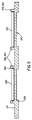
- Figure 3 is a semi-diagrammatical cross-sectional view of the label of Figure 1.
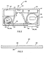
- Figure 4 is a semi-diagrammatical rear view of another embodiment of the camera.
- Figure 5 is a cross-sectional view of the camera of Figure 4 taken substantially along line 5-5 of Figure 4.
- Figure 5a is a semi-diagrammatical view of an embodiment of a Bernoulli labeler.
- Figure 6 is semi-diagrammatical view of a first embodiment of the labeler head of the labeler of Figure 5a.
- Figure 7 is a fragmentary sectional view of the labeler head of Figure 6, indicating the orientation of the bores for the gas jets.
- Figure 8 is a perspective view of a second embodiment of the labeler head.
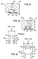
- Figure 9 is an elevation section view through the labeler head of Figure 8.
- Figure 10 is an elevation view of a third embodiment of the labeler head.
- Figures 11-12 are plan views of modifications of the labeler heads of Figures 6-10.
- Figures 13-16 are perspective views, some in section, of a fourth embodiment of the labeler head.
- Figure 17 is a plan view and Figures 18-21 are perspective views, some in section, of a fifth embodiment of the labeler head.
-
- A
camera 100 has acasing 112 that encloses afilm area 114. Thecasing 112 has one or more light-transmissive regions 116 that define undesired stray light paths into thefilm area 114. Thecasing 112 also hasopaque regions 118 that block admission of light into thefilm area 114. Alabel 120 is adhered to thecasing 112. Thelabel 120 has an opaque portion 122 that is superimposed on the light-transmissive region 116 and blocks transmission of light through the light-transmissive region 116 of thecasing 112. The light-transmissive regions 116 can be holes or gaps 124 in thecasing 112, but it is preferred that the light-transmissive regions 116 are solid parts of thecasing 112. - Referring now particularly to Figures 1-2, the
casing 112 of thecamera 100 includes aframe 126 and front and rear covers 128,130 joined over theframe 126. Thecasing 112 has interior and exterior surfaces 129,131. The invention is generally described herein in relation to acamera 100 having asingle label 120 adhered to anexterior surface 131, but it will be understood that alabel 120 can be on aninterior surface 129 andmultiple labels 120 can be used. Asingle label 120 mounted to anexterior surface 131 is preferred for ease of manufacturing. - The
film area 114 includes anexposure chamber 134 to which light is directed by a takinglens 136 for picture taking. Within thecasing 112, in thefilm area 114,unexposed film 132 is moved from afirst film chamber 138, across theexposure chamber 134, to asecond film chamber 140. The type of film and manner of film transport is not critical. For example, a one or two chamber film cartridge or a cartridgeless film roll can be used. Film can be prewind and be returned to a film cartridge at the time of film exposure, or rewinding after exposure can be required. The embodiment illustrated in the figures is a one-time use camera 100, in which afilm roll 142 housed in an otherwise emptyfilm supply chamber 138, is moved by a film transport (indicated schematically by box 144) across theexposure chamber 134 to a film cartridge 145 housed in afilm cartridge chamber 140. Theexposure chamber 134 is between the opposed film chambers 140,142 and has a baffle through which light is admitted from the takinglens 136 when film exposures are made. The chambers 134,138,140 are parts of theframe 126. Joined to theframe 126 are various camera components 147 (illustrated by boxes in Figure 2) that, together with theframe 126, comprise a frame assembly 146. Examples of such components include a viewfinder, a flash unit, an shutter mechanism, and thefilm transport 144. Thecomponents 147 include appropriate control features that extend through thecasing 112. The shutter mechanism includes a shutter button. Thefilm transport 144 includes a thumbwheel or advance lever. Suitable components and other features of thecamera 100 that are not illustrated, are well known to those of skill in the art. - Referring now to Figure 1, the light transmissive region 116 is an opening 116a between the front and rear covers 128,130, in which a screwdriver or other tool can be inserted when the
camera 100 is opened for film processing. It is preferred that thecamera 100 not have such openings that could admit light to thefilm area 114, since foreign objects could penetrate thelabel 120 at an opening and damage the interior of thecamera 100 or allow light leakage. It is preferred that any and all light-transmissive regions 116 of thecasing 112 be free of openings 116a. Preferred light-transmissive regions 116 of thecasing 112 are regions 116b of solid translucent plastic. The term "translucent" is used herein in a technical sense, to describe a medium which transmits rays of light so diffused that objects cannot be seen distinctly. Even when thin, plastics used for one-time use camera bodies, such as polystyrene, are tough and resistant to bending, stretching, and punctures.Labels 120 are thinner and less resistant to such deformation. It is preferred for convenience in production that thelabel 120 is very thin relative to thecasing 112 and compliant, but resistant to punctures. An example of asuitable label 120 material is a polymeric blend of polystyrene and polyethylene. Even if abused, such alabel 120 is unlikely to admit light and spoil thefilm 132. There is a risk, however, that an intruding object could bend thelabel 120 and cause pressure marks on thefilm 132. This risk is not present when the only transmissive regions 116 on acamera 100 are regions 116b of solid, translucent plastic. - Single or multiple light-transmissive regions 116 can be present on the
casing 112. All of the light-transmissive regions 116 can be covered by asingle label 120 ormultiple labels 120 can be used. For convenience, the invention is generally discussed herein in relation to acamera 100 having a single translucent region 116b covered by asingle label 120. - Referring again to Figures 1-2, the
rear cover 130 includes translucent region 116b andopaque regions 118. Theopaque regions 118 do not allow light to pass through. The translucent region 116b is thinner than theopaque regions 118 and is continuous with theopaque regions 118. The cover portions 128,130 are each preferably a one-piece plastic casting produced by injection molding or the like. The translucent region 116b can differ in opacity from theopaque regions 118 on the basis of a difference in composition rather than a difference in thickness; but this is not preferred, since this approach does not provide an advantage of reduced size. - The
rear cover 130 closes the chambers 134,138,140. Therear cover 130 of thecamera 100 is preferably a one-piece plastic casting produced by injection molding or similar process. Therear cover 130 is composed of a material that has a uniform opacity per unit volume, but the part of therear cover 130 that forms the translucent region 16b is sufficiently thin as to be translucent and transmit light. Therear cover 130 can be neutral in color or can have a hue, in which case, the transmitted light will be colored.Opaque regions 118 and translucent regions 116b are continuous with each other, but the translucent regions 116b are thinner. The translucent region 116b is shown as overlapping theexposure chamber 134 andfilm supply chamber 138. Without thelabel 120, light can pass through the translucent region 116b and strike thefilm 132 within theexposure chamber 134 and/or the film chambers 128,130. The translucent region 116b can be of different sizes and in different positions as required by aparticular camera 100 design. In thecamera 100 design shown, the reduced thickness at the translucent region 116b decreases contact of thefilm 132 with theback cover 130. To keep thefilm 132 positioned in a flat or curved film plane appropriate for a particular lens system, theback cover 130 can have one or more longitudinal ribs or other protrusions. (Ribs are illustrated in Figure 2 by a dashedline 148.) The ribs or protrusions act as a platen for thefilm 132 in theexposure chamber 134. Theback cover 130 can be convoluted to provide the ribs. In that case the ribs can be translucent. Alternatively, the ribs can be provided as an array of thickenedopaque regions 118 interposed in an interrupted translucent region 116b. - The
label 120 is adhered to thecasing 112. In the embodiment shown in the figures, thelabel 120 is adhered to therear cover 130 and to thefront cover 128. Thelabel 120 is shown folded over anedge 149. Thelabel 120 is preferably compliant to allow such folding without creasing and to allow easy placement on curved surfaces. The opaque portion 122 of thelabel 120 covers the translucent region 116b. The opacity of thelabel 120 can be provided in a variety of different ways. Referring to Figure 3, a convenient way of providing opacity is the use of amultiple layer label 120, in which one of the layers is metallized plastic or metallic foil. In Figure 3 anadhesive layer 150 is bonded to alayer 152 of foil or metallized plastic, to which is bonded alayer 154 of printable material such as paper or printable plastic. Such labels are inexpensive and are well known to those of skill in the art. - The opaque portion 122 of the
label 120 can encompass the entire label or can be limited to only the part of thelabel 120 overlying the translucent portion 116b of thecasing 112. This is largely a matter of artistic design. For example, if thecasing 112 of thecamera 100 is colored, thelabel 120 can have one or more transparent areas to shown the color of thecasing 112. - The
camera 100 has obstructions 156 that extend inward or outward relative to the rest of thecamera casing 112 or otherwise present a discontinuity or obstruction 156 in thecasing 112. The obstructions 156 cannot be covered bylabel 120 without degradation of the function or appearance of the camera or both. In some embodiments such as the one shown in Figure 1, covering the obstructions 156 partially or completely with thelabel 120 would also present a risk of light leakage to the translucent region 116b of thecasing 112. Many obstructions 156 are control elements 158; such as the viewfinder 158a, the thumbwheel 158b, and the shutter button 158c shown in Figure 1; that must be accessible to the user for picture taking. (A control element 158 is considered an obstructions 156, if it must remain uncovered or presents sufficient surface relief to hinder label placement.) Other obstructions 156, such as the grip elements 160 shown in Figure 1 could receive alabel 120; but not without degradation of function. The grip elements 160 are small structures that help the user hold thecamera 100. Still other obstructions (not shown) are interference features that abruptly change camera contours and for that reason cannot be cleanly labeled. In following discussion of Figures 1 and 2, the viewfinder 158a and grip elements 160 are the only obstructions 156 discussed, since the other obstructions 156 are spaced from thelabel 120. - Adjoining the obstructions 156 are
obstruction boundaries 162, parts of thecasing 112 that define limits of the area that can be covered by alabel 120. On thecasing 112, theobstruction boundaries 162 define limits of the area that can receive alabel 120. It is highly preferred thatobstruction boundaries 162 of thecasing 112 are part of anopaque region 118 rather than the translucent region 116b.Obstruction boundaries 162 on the translucent region 116b present a risk of light piping. Theobstruction boundaries 162 receive thelabel 120, without deleterious effect. Depending upon the position of the obstruction 156 on thecamera casing 112, theobstruction boundary 162 can surround all or part of the obstruction 156. - The
label 120 is adhered to thecasing 112 in registration with theobstruction boundaries 162. For any obstruction 156 adjoining thelabel 120, edges of thelabel 120 overlap and are coextensive withobstruction boundaries 162 for that obstruction 156. This assures good contact of thelabel 120 with thecasing 112. As a result, the translucent region can closely adjoin an obstruction 156, yet still be rendered opaque by thelabel 120. Theobstruction boundary 162 can be covered by an outer edge of thelabel 120, as is the case in Figure 1, with the obstruction boundary 162a around the viewfinder. Alternatively, theobstruction boundary 162 can be covered by an inner edge of thelabel 120, as is the case in Figure 1 with theobstruction boundaries 162 around each of the grip elements 160. - With an obstructed
casing 112, it is preferred that thelabel 120 is adhered to thecasing 112 in registration with theobstruction boundaries 162 such that thelabel 120 is aligned with the translucent region and theobstruction boundary 162 translationally is within 0.6 mm, that is, the tolerance for the location for each edge of thelabel 120 is ± 0.3 mm. It is more preferred that theobstruction boundary 162 translationally is within 0.4 mm of the label edge (a tolerance of ± 0.2 mm) and still more preferred within 0.2 mm (a tolerance of ± 0.1). This precise positioning of thelabel 120 protects against light leakage through the transmissive region 116, despite close placement of the transmissive region 116 and theobstruction boundaries 162. - The
obstruction boundary 162 can border the transmissive region 116 on one or more sides and can even surround the transmissive region 116. Referring now particularly to Figures 4-5, The obstruction 156 is a grip element 164 in the shape of an indicia, shown in Figures 4-5 as the letter "K". - Referring now to Figures 5a-21, the
labels 120 can be attached within 0.6 mm ofobstruction boundaries 162 using the Bernoulli effect labeler heads 48,labeling apparatus 10, and methods disclosed in U.S. Patent No. 5,472,543. Separations of 0.4 mm or less and 0.2 mm or less can be provided by careful tolerancing of all manufacturing components or by culling of cameras with the greatest variance, or both. Thelabeler head 48 comprises amain member 50 having asupport surface 52 which may be flat, or convex and substantially cylindrical with an axis of curvature. Aplenum 54 within themain member 50 communicates with a plurality ofbores 56 extending from theplenum 54 through thesupport surface 52. Thebores 56 are angled with respect to thesupport surface 52 and arranged in an array so that jets of gas issuing from the array will cause alabel 120 to be drawn onto thesupport surface 52 when thelabel 120 is presented to thesupport surface 52 and a first side of thelabel 120 is brought into close proximity of the jets, thereby causing a zone of reduced gas pressure to be formed between the support surface and the first side of the label and establishing a pressure differential across thelabel 120 to hold thelabel 120 on a film of gas flowing over thesupport surface 52. A gas supply (not shown) provides a flow of gas into theplenum 54 and through the angled bores 56. The gas supply provides pulses of higher pressure gas to propellabels 120 against thecamera casing 112 to be labeled and can provide a vacuum to thelabeler head 48 as necessary to holdlabel 120. - In the
apparatus 10, anelongated carrier strip 12 has a surface having low affinity for the adhesive-backed side of a plurality of pressure-sensitive labels 120. Display sides of the labels face outward from thecarrier strip 12.Labels 120 can be of practically any shape and are moderately stiff, to facilitate ready removal from thecarrier strip 12. The carrier strip is wound in alarge roll 24 prior to label removal. The usedcarrier strip 12, depleted oflabels 120, is likewise wound in aroll 26. Therolls apparatus 10 for rotation such thatstrip 12 is pulled around anidler roller 20 and then around the edge of apeeler plate 22. Because the adhesive backing onlabels 120 has a low affinity for the surface ofstrip 12 and becauselabels 120 have a certain resistance to bending, the labels release gradually and automatically fromstrip 12 as the strip passes around the edge of thepeeler plate 22 and are presented substantially tangentially to thelabeler head 48. Thelabeler head 48 is reciprocated in directions indicated by double-headedarrow 28 by adrive 29. Thecasing 112 is supported on a bracing or conveyor 30. A nest can be used to support thecasing 112. - The
main member 50 of thelabeler head 48 is a material such as metal or rigid plastic or a resilient material. Thesupport surface 52 is smooth and typically flat. Withinmain member 50, aplenum 54 communicates with a plurality ofbores 56 which extend fromplenum 54 to supportsurface 52. In a particular embodiment of the invention, bores 56 have a diameter in the range of 0.012 to 0.032 inch (0.030 to 0.081 cm) and are set at an angle to supportsurface 52 in the range of 5 to 45 degrees. Aport 58 is provided throughmain member 50 to connectplenum 54 to the gas supply to provide pressurized air or subatmospheric pressure.Bores 56 are arranged in an array so that jets of gas issuing from the bores will causelabel 120 to be drawn ontosupport surface 52 when thelabel 120 is presented to the support surface and its display side is brought into close proximity with the jets of gas. The flow of gas causes a zone of reduced gas pressure to be formed betweensupport surface 52 andlabel 120, in accordance with the Bernoulli Effect, thereby establishing a pressure differential across thelabel 120 to hold thelabel 120 in position on a film of gas flowing over the support surface. The array is also configured so that, once released,label 120 will move relative to supportsurface 52 and reposition itself accurately against one or more stops 60 provided on or adjacent the support surface. Just as shown in Figures 6, and 13-21, with the labeler head of Figures 6 to 9,label 120 covers the portion of the array ofbores 56 which are at least partially directed towardstops 60, when thelabel 120 is positioned against the stops. Thus, the rear or upstream edge of thelabel 120 is not subjected to air flows which could dislodge it from its position against the stops.Stops 60 can be supported onresilient springs 61, which allow the stops to be depressed to the level ofsupport surface 52 duringlabel 120 application. Preferably, stops 60 are made from a material to which the adhesive of thelabels 120 will not stick readily, such as Rulon, a plastic material made by Dixon Industries Corp. of Bristol, R.I. U.S.A. - Figures 8-9 illustrate another
labeler head 48 useful with theapparatus 10, in whichflat support surface 52 is replaced by aresilient insert 62 of a material such as silicon rubber which has cylindrical,convex support surface 64 having an axis of curvature transverse to the direction from which label 120 is fed tolabeler head 48. A pair of stop pins orabutments 66 are provided on one side ofsupport surface 64. Stop pins 66 preferably also are made from a non-stick material such as Rulon. In a particular embodiment, at least a portion ofbores 56 are angled so that their jets of gas are directed at least partially toward stop pins 66 and do not oppose movement oflabel 120 onto the labeler head. By "at least partially toward" is meant that none of the air jets includes a vector component which would oppose movement of thelabel 120 acrosssupport surface 64. Forround labels 120, the jets frombores 56 preferably are symmetrically placed on either side of the path of thelabel 120 onto the labeler head. Round labels 120 upon release will move acrosssupport surface 64 into accurate engagement with stop pins 66. Thelabel 120 may be provided with a radially inwardly or outwardly extending feature which is engaged by the stop pins 66. Thelabel 120 may have a central aperture; and themain member 50 may have a locator pin (not illustrated in this embodiment) positioned centrally of the array, the pin being sized to pass through the aperture of thelabel 120 and preferably being retractable. Non-symmetric arrays of bores are also useful, for example, withrectangular labels 120. The resilient material ofinsert 62 and the cylindrical shape ofsupport surface 64 ensure that when the labeler head is pressed against acasing 112 to applylabel 120, essentially line contact is first established due to the cylindrical shape and then the insert compresses, so that thelabel 120 is smoothly applied without bubbles or wrinkles. - Figure 10 shows a modification of the labeler head of Figures 8-9. Within
main member 50, asecond plenum 55 communicates with one ormore bores 57 which extend fromplenum 55 to supportsurface 64. Such asecond plenum 55 and bores 57 also may be included in the other labeler heads discussed. Aport 59 is provided fromplenum 55 to a source of pressurized air; so that, a blast of air throughbores 57 may be used to blow thelabel 120 onto thecasing 112 to be labeled. - Figures 11-12 illustrate typical arrays of
bores 56 for labeler heads 48 of Figures 6-10, having flat support surfaces 52 approximately 0.6 and 1.0 inch (1.52 and 2.54 cm), respectively, in width ("W" in Figures 14-15). The number of bores depends upon the area and weight of thelabel 120. The arrows indicate the direction of the jets frombores 56 towardstops 60, preferably so that no vector component of any jet will oppose movement oflabel 120 ontosupport surface 52. Forround labels 120, the jets preferably are symmetrically placed relative to the path of thelabel 120. Thus,round labels 120 upon release will move acrosssupport surface 52 into accurate engagement with stops 60. Similar arrays of bores may be used forlabels 120 of other shapes. - Figures 13-16 illustrate another
labeler head 48 which is suited for applyinglabels 120 having a central hole 108 and a radially inwardly extending feature such as anotch 70 extending over an arc of the circumference of thelabel 120. In this case,main member 50 is provided with a centrally positioned, taperedlocator pin 72 which extends fromsupport surface 52. The diameter oflocator pin 72 preferably is only slightly smaller than that of central hole 108, to accurately center thelabel 120 on thelabeler head 48. Surroundinglocator pin 72 is an array ofangled bores 74 whose jets extend in generally the same sense or circular direction aboutlocator pin 72. Whenlabel 120 is released so thatlocator pin 72 enters hole 108, thelabel 120 will move down onto and spin aroundlocator pin 72 untilnotch 70 settles over an axially extending stop orabutment 76, thereby stopping movement of thelabel 120 and accurately centering and angularly positioning it for application. As shown in Figure 16,label 120 covers the portion of the array ofbores 74 which are at least partially directed towardstop 76, when thelabel 120 is positioned against the stop. Thus, the circumferential edge of thelabel 120 is not subjected to air flows which could dislodge it from its position against the stop. Preferablyabutment 76 is retractable during application of thelabel 120, (not illustrated). As shown in Figures 15-16,main member 50 has a central stepped passage, which is surrounded byplenum 54, and in whichlocator pin 72 is slidably mounted. Ahead 80 on the locator pin is pressed against by aspring 82; so that,locator pin 72 is retractable but is biased to extend beyondsupport surface 52 as illustrated. As will be discussed further with respect to Figure 20, the retractability oflocator pin 72 facilitates use oflabeler head 48 to accurately placelabel 120 around an opening 122 in thecasing 112 to be labeled. Subatmospheric pressure can be applied toplenum 54 after thelabel 120 has been acquired and repositioned. - Figures 17-21 illustrate another
labeler head 48 which also is particularly suited for applyinglabels 120 having a central hole 108 and aperipheral notch 70. In this instance,locator pin 72 can be withdrawn belowsupport surface 52 by any convenient means such as a solenoid or air cylinder (not illustrated), to permitlabel 120 to be presented and accurately positioned in a different manner. Thus, the diameter oflocator pin 72 can be substantially less than that of hole 108. To facilitate adjustment of the lateral positions ofstops 60 and to allow the stops to be depressed to the level ofsupport surface 52,support surface 52 preferably ends at a recess having anedge 84 which along a portion of its length is shaped geometrically similarly to the portion oflabel 120 comprisingnotch 70. Opposite this portion ofedge 84 and extended over the recess are stops 60, laterally positioned so that the first stop can engage one side ofnotch 70 and the second stop can engage the periphery oflabel 120 on the opposite side ofnotch 70 from the first stop, as seen most clearly in Figures 20 and 23. Thelabel 120 is presented to supportsurface 52 along a path directly toward stops 60. Rather than the circular array of bores of the embodiment of Figures 16-19, a first pair ofbores 86 are provided on the opposite side oflocator pin 72 fromstops 60 and are directed at angles toward opposite sides oflocator pin 72; a second pair ofbores 88 are directed directly towardstops 60 on opposite sides oflocator pin 72; and a single, angular orientation bore 90nearest stops 60 is directed at an angle toward the more distant ofstops 60.Bore 90 may be positioned on either side of the path oflabel 120. In a particular embodiment, none of the jets includes a vector force component which would oppose movement of thelabel 120 acrosssupport surface 52.Support surface 52 preferably is flat but also may have a cylindrical, convex shape of the type shown in Figures 8-9. With this arrangement, oncelocator pin 72 has been withdrawn, alabel 120 presented in the direction shown will be moved byjets support surface 52 towardstops 60 and will be turned byjet 90; so that, stops 60 accurately engagenotch 70 and the periphery of thelabel 120.Locator pin 72 can then be extended through central hole 108. As shown in Figures 20 and 23, in the embodiment of Figures 17-21label 120 covers the portion of the array ofbores stops 60, when thelabel 120 is positioned against the stops. Thus, the circumferential edge of thelabel 120 is not subjected to air flows which could dislodge it from its position against the stops.Labels 120 of different shapes may be acquired and positioned using somewhat different arrays of jets and stops.
Claims (10)
- A camera comprising:a casing enclosing a film area, said casing having a translucent region defining a stray light path into said film area;a label adhered to said casing, said label having an opaque portion covering said translucent region.
- The camera of claim 1 wherein said casing has a frame defining a pair of opposed film chambers, an exposure chamber between said film chambers, and a rear cover closing said chambers, said film area including said chambers; and said label is compliant.
- The camera of claim 2 wherein said rear cover includes said translucent region.
- The camera of claim 1, 2, or 3 wherein said translucent region is imperforate.
- The camera of claim 1, 2, 3, or 4 wherein said casing has a grip element bordering said translucent region on at least one side.
- The camera of claim 1, 2, 3, 4, or 5 wherein said casing has an opaque region thicker than and continuous with said translucent region.
- The camera of claim 6 wherein said opaque region includes an obstruction boundary and said label is in registration with said obstruction boundary and spaced from said obstruction boundary by less than 0.6 mm or less.
- The camera of claim 7 wherein said label is spaced from said obstruction boundary by 0.4 mm or less.
- The camera of claim 7 wherein said label is spaced from said obstruction boundary by 0.2 mm or less.
- The camera of claim 7, 8, or 9 wherein said obstruction boundary borders said translucent region on at least one side.
Applications Claiming Priority (2)
| Application Number | Priority Date | Filing Date | Title |
|---|---|---|---|
| US360909 | 1994-12-21 | ||
| US09/360,909 US6330396B1 (en) | 1999-07-26 | 1999-07-26 | Camera having light-blocking label |
Publications (1)
| Publication Number | Publication Date |
|---|---|
| EP1074880A1 true EP1074880A1 (en) | 2001-02-07 |
Family
ID=23419896
Family Applications (1)
| Application Number | Title | Priority Date | Filing Date |
|---|---|---|---|
| EP00202523A Withdrawn EP1074880A1 (en) | 1999-07-26 | 2000-07-14 | Camera having light-blocking label |
Country Status (3)
| Country | Link |
|---|---|
| US (1) | US6330396B1 (en) |
| EP (1) | EP1074880A1 (en) |
| JP (1) | JP2001066736A (en) |
Families Citing this family (5)
| Publication number | Priority date | Publication date | Assignee | Title |
|---|---|---|---|---|
| JP2000330243A (en) * | 1999-03-12 | 2000-11-30 | Fuji Photo Film Co Ltd | Outer package sheet for camera and camera |
| JP2002116488A (en) * | 2000-10-06 | 2002-04-19 | Fuji Photo Optical Co Ltd | Camera |
| JP2002351020A (en) * | 2001-05-28 | 2002-12-04 | Fuji Photo Film Co Ltd | Film unit with lens |
| US7308195B2 (en) * | 2002-09-30 | 2007-12-11 | Matsushita Electric Industrial Co., Ltd. | Collapsible lens barrel and optical instrument using the same |
| US6714727B1 (en) | 2003-04-14 | 2004-03-30 | Eastman Kodak Company | Camera capable of having alternatively positioned mode indicator |
Citations (3)
| Publication number | Priority date | Publication date | Assignee | Title |
|---|---|---|---|---|
| US4797697A (en) * | 1987-09-14 | 1989-01-10 | W. Haking Enterprises Limited | Miniature 110 camera with four-panel wrapper |
| JPH0954396A (en) * | 1995-08-11 | 1997-02-25 | Fuji Photo Film Co Ltd | Film unit with lens |
| DE19600270A1 (en) * | 1996-01-05 | 1997-07-10 | Agfa Gevaert Ag | Device for photographic video recording on strip-shaped recording material |
Family Cites Families (16)
| Publication number | Priority date | Publication date | Assignee | Title |
|---|---|---|---|---|
| DE1208184B (en) | 1963-12-21 | 1965-12-30 | Voigtlaender Ag | Photographic camera with built-in electronic flash unit |
| US4540265A (en) | 1983-01-24 | 1985-09-10 | Eastman Kodak Company | Energy-saving electronic flash apparatus |
| US4972649A (en) | 1986-08-20 | 1990-11-27 | Fuji Photo Film Co., Ltd. | Photographic film package and method of making the same |
| US4827291A (en) * | 1986-12-09 | 1989-05-02 | Avner, Inc. | Photographic aid apparatus for photographing a uniformly illuminated object |
| US5068575A (en) | 1991-02-21 | 1991-11-26 | Eastman Kodak Company | Indirect storage capacitor voltage sensing means for a flyback type DC-to-DC converter |
| JP2888682B2 (en) | 1991-11-14 | 1999-05-10 | 富士写真フイルム株式会社 | Method of manufacturing film unit with lens |
| US5235366A (en) | 1992-03-09 | 1993-08-10 | Eastman Kodak Company | Single use photographic film package and camera |
| US5470420A (en) | 1992-07-31 | 1995-11-28 | Eastman Kodak Company | Apparatus for label application using Bernoulli Effect |
| JPH07114147A (en) | 1993-10-14 | 1995-05-02 | Konica Corp | Film unit with lens |
| JPH0811567B2 (en) | 1993-12-29 | 1996-02-07 | 株式会社正和テクノシステムズ | Chip component loading device |
| JP3379031B2 (en) | 1994-09-13 | 2003-02-17 | コニカ株式会社 | Film unit with lens |
| US5614975A (en) | 1994-11-03 | 1997-03-25 | Eastman Kodak Company | Film brake applied by exposure initiation |
| US5652930A (en) | 1994-12-16 | 1997-07-29 | Eastman Kodak Company | Camera information display |
| US5815738A (en) * | 1997-04-02 | 1998-09-29 | Eastman Kodak Company | Compact one-time-use camera |
| US5761542A (en) | 1997-06-03 | 1998-06-02 | Eastman Kodak Company | One-time-use camera with film door which when opened to remove film cartridge breaks anti-backup pawl for film winder wheel |
| US5873002A (en) | 1997-12-23 | 1999-02-16 | Eastman Kodak Company | Cartridge loading apparatus and methods |
-
1999
- 1999-07-26 US US09/360,909 patent/US6330396B1/en not_active Expired - Fee Related
-
2000
- 2000-07-14 EP EP00202523A patent/EP1074880A1/en not_active Withdrawn
- 2000-07-26 JP JP2000225410A patent/JP2001066736A/en active Pending
Patent Citations (3)
| Publication number | Priority date | Publication date | Assignee | Title |
|---|---|---|---|---|
| US4797697A (en) * | 1987-09-14 | 1989-01-10 | W. Haking Enterprises Limited | Miniature 110 camera with four-panel wrapper |
| JPH0954396A (en) * | 1995-08-11 | 1997-02-25 | Fuji Photo Film Co Ltd | Film unit with lens |
| DE19600270A1 (en) * | 1996-01-05 | 1997-07-10 | Agfa Gevaert Ag | Device for photographic video recording on strip-shaped recording material |
Non-Patent Citations (1)
| Title |
|---|
| PATENT ABSTRACTS OF JAPAN vol. 1997, no. 06 30 June 1997 (1997-06-30) * |
Also Published As
| Publication number | Publication date |
|---|---|
| US6330396B1 (en) | 2001-12-11 |
| JP2001066736A (en) | 2001-03-16 |
Similar Documents
| Publication | Publication Date | Title |
|---|---|---|
| US6190065B1 (en) | Thermal imaging tape cartridge | |
| JPH0723780Y2 (en) | Camera data imprinting device | |
| US20120317784A1 (en) | Two-Piece Protective Carrying Case | |
| JPH06332118A (en) | Film loading device for film unit with lens | |
| EP1072940B1 (en) | Camera having label-stopped optical system | |
| US6330396B1 (en) | Camera having light-blocking label | |
| US5576793A (en) | Lens-fitted photographic film unit | |
| US5339125A (en) | Camera with data imprinting device | |
| KR20010106190A (en) | Rear projection type screen | |
| US5784652A (en) | Modular camera with cassette chamber accessible through outerbody | |
| EP0790528B1 (en) | Index-printed photograph film bag | |
| EP1037099A1 (en) | Camera and wrapping sheet thereof | |
| US5864717A (en) | Photographic roll-film pack with a picture-taking lens | |
| US6301437B1 (en) | Lens-fitted photo film unit having a recess and ridges in a housing thereof | |
| US5915299A (en) | Stamp making unit and package therefor | |
| JPH07199413A (en) | Strip film attaching / detaching device and method for manufacturing the same | |
| CA2111202A1 (en) | Image transfer apparatus | |
| US5381198A (en) | Adaptor for instant camera | |
| EP0627653B1 (en) | Paper mask device | |
| US5790169A (en) | Device for storing picture or code information displayed on a screen, carrier cards for such devices and method for the transmission of a code | |
| EP1267202B1 (en) | Manufacturing method for a lens-fitted photo film unit having a selectively observable mark | |
| JPH04269736A (en) | Image holding template for instant film assembly | |
| US6244760B1 (en) | Camera having mechanism for securely guiding out film | |
| JP2004093899A (en) | Label sheet and label sticking method using same | |
| JP3667416B2 (en) | Film unit with lens |
Legal Events
| Date | Code | Title | Description |
|---|---|---|---|
| PUAI | Public reference made under article 153(3) epc to a published international application that has entered the european phase |
Free format text: ORIGINAL CODE: 0009012 |
|
| AK | Designated contracting states |
Kind code of ref document: A1 Designated state(s): DE FR GB |
|
| AX | Request for extension of the european patent |
Free format text: AL;LT;LV;MK;RO;SI |
|
| 17P | Request for examination filed |
Effective date: 20010720 |
|
| AKX | Designation fees paid |
Free format text: DE FR GB |
|
| STAA | Information on the status of an ep patent application or granted ep patent |
Free format text: STATUS: THE APPLICATION HAS BEEN WITHDRAWN |
|
| 18W | Application withdrawn |
Effective date: 20041018 |