EP1074765A1 - Shackle (clevis) for hooking onto a chain - Google Patents
Shackle (clevis) for hooking onto a chain Download PDFInfo
- Publication number
- EP1074765A1 EP1074765A1 EP00116158A EP00116158A EP1074765A1 EP 1074765 A1 EP1074765 A1 EP 1074765A1 EP 00116158 A EP00116158 A EP 00116158A EP 00116158 A EP00116158 A EP 00116158A EP 1074765 A1 EP1074765 A1 EP 1074765A1
- Authority
- EP
- European Patent Office
- Prior art keywords
- shackle
- chain
- link
- ring
- fork
- Prior art date
- Legal status (The legal status is an assumption and is not a legal conclusion. Google has not performed a legal analysis and makes no representation as to the accuracy of the status listed.)
- Granted
Links
Images


Classifications
-
- F—MECHANICAL ENGINEERING; LIGHTING; HEATING; WEAPONS; BLASTING
- F16—ENGINEERING ELEMENTS AND UNITS; GENERAL MEASURES FOR PRODUCING AND MAINTAINING EFFECTIVE FUNCTIONING OF MACHINES OR INSTALLATIONS; THERMAL INSULATION IN GENERAL
- F16G—BELTS, CABLES, OR ROPES, PREDOMINANTLY USED FOR DRIVING PURPOSES; CHAINS; FITTINGS PREDOMINANTLY USED THEREFOR
- F16G15/00—Chain couplings, Shackles; Chain joints; Chain links; Chain bushes
- F16G15/04—Quickly-detachable chain couplings; Shackles chain links with rapid junction means are classified according to the corresponding kind of chain
- F16G15/06—Shackles designed for attachment by joint pins to chain elements, e.g. D-shackles so called harp links; the D-chain links are classified according to the corresponding kind of chain
Definitions
- the present invention relates to a shackle structure to be secured to the link of a chain.
- a shackle commonly also referred to as a clevis or shank, is composed, as known, of a half-ring usually in steel with a U or horseshoe shape, wherein the ends of the legs are widened and perforated to allow the passage of a bolt for closure which can be threaded to screw into one of the holes, also threaded, or which alternatively can be locked to the relative leg by means of a split pin.
- a shackle is widely used for example for connecting two chain sections one to the other, for securing a chain to a fixed eye or to the anchor, or to a buoy.
- a shackle is attached by linking the bolt to the chain link to be hooked, and this, for standard chains wherein the span in the link theoretically extends axially for a section equal to three times the diameter of the link, means in practice that the diameter of the bolt of the shackle has to be smaller than that of the chain link.
- the object of the present invention is therefore that of providing a shackle which remedies the disadvantages suffered by a traditional shackle and in particular one object is that of providing a shackle for a chain which provides solid hooking to the link of a chain and namely hooking with resistance to breakage from tensile stress no less than the intrinsic resistance of each link of the chain.
- Another object of the present invention is that of providing a shackle for a chain which has a simple structure and principle of operation and for this reason is also inexpensive.
- Yet another object of the present invention is that of providing a shackle for a chain which can also be adapted with versatility to links of chains of different sizes.
- a shackle for a chain in accordance with the present invention, of the type comprising:
- the shackle of the present invention advantageously offers a point of hooking to the chain which has a resistance to breakage from tensile stress equal at least to the intrinsic resistance of a link of the chain, given that the shackle can embrace externally the entire link with a bolt of diameter even greater than that of the link itself.
- the sliding on the chain of the shackle of the present invention is locked in that, while the link is inserted in the fork and restrained therein by the bolt brought into the position of closure, the upper and respectively lower wall of the fork hit against the arch of the chain link above the hooked link and respectively on the arch of the chain link below the hooked link and the fork remains restrained there.
- the shackle 1 comprises an external U-shaped support half-ring formed by two legs 3 and 3' rigidly connected via an arch 5.
- each leg 3 and 3' of the shackle 1 defines enlargements 7 and 7' having respective transverse through holes 9 and 9', distanced yet aligned, wherein a threaded bolt 11 is guided to slide.
- the bolt 11 is mobile between a position of opening of the shackle 1, occupied when the head 13 is moved away from the hole 9, and a position of closure of the shackle, occupied when the head 13 hits against the external side wall of the hole 9 and the threaded end of the bolt 11 is inserted in the hole 9'.
- the end of the bolt 11 is threaded so as to screw the bolt 11 to the hole 9', also threaded, in such a way as to guarantee locking of the closure of the shackle.
- the shackle 1 also comprises a fork 15 placed inside the support half-ring, whose two legs 39 and 39' are integral with and parallel to the corresponding legs 3 and 3' of the support half-ring, and whose mouth 41 is turned on the side of the bolt 11.
- the fork 15 is in the form of an insert with a U-shaped internal side wall 17 dimensioned so as to be inserted simultaneously on a diameter of the two straight sides of the chain link which has to be hooked.
- the diameter of the bolt 11 has been made equal to the diameter of chain to be hooked by the shackle 1, but a bolt can likewise be used with even greater diameter.
- the U-shaped internal side wall 17 of the insert 15 has a mouth 41 greater than the diameter of the bolt 11 and depth greater by three times the diameter of the bolt 11.
- the diameter of the bolt 11 is 10 mm exactly like the diameter of the link 19 of chain 21 to be hooked.
- the opening of the mouth 41 of the internal side wall 17 is 12 mm, while its depth is 32 mm and its height 8 mm.
- the insert 15 is attached onto the shackle 1 by means of a groove 23 and respectively 23' which extends from the front end to the rear end of the external side walls of the insert 15.
- the cross section of the groove 23 and respectively 23' defines a circumference arc with curvature equal to that of the round leg 3 and respectively 3' of the half-ring of the shackle 1.
- the insert 15 is engaged on the half-ring of the shackle 1 by first inserting frontally the rear wall of the insert 15 in the mouth of the half-ring of the shackle 1 and then pushing with a light pressure the groove 23 and respectively 23' to slide on the internal side wall of the adjacent leg 3 and respectively 3' of the half-ring of the shackle 1 until the rear end of the groove 23 and respectively 23' rests on the arch 5 of the half-ring of the shackle 1.
- each front end 37 of the two legs of the fork 15 also has a groove, shaped and orientated like the bolt 11 so as to guide its sliding.
- these grooved portions 37 engage on the bolt 11 and thus also allow support of the fork 15.
- the rear side wall of the insert 15 defines with the arch 5 of the shackle 1 a span 25 for hooking to the shackle 1 the element to be connected to the chain, represented by way of an example by a ring 27.
- the removable engaging between the insert 15 and the half-ring of the shackle 1 advantageously allows the ring 27 to be hooked preliminarily onto the shackle 1.
- the innermost portion of the insert 15 has a reduction in thickness to allow insertion of the shackle 1 on the link and consequently lock sliding of the same along the chain 21.
- the operation of hooking of the shackle 1 to the link 19 of the chain 21 in fact provides, in the first place, for frontal insertion of the mouth of the fork on the diameter of the median point of the straight sides at the rear 29B first and front 29A subsequently of the chain link to be hooked, in such a way that the upper and respectively lower wall of the reduced thickness 31 of the fork hit against the lower arch of the overlying chain link 35 and respectively on the upper arch of the underlying chain link 33, thus locking sliding of the shackle 1 along the chain 21.
- the bolt of the present invention can be, as in the aforesaid preferred embodiment, of the unlosable type.
- the innermost tip of the threaded portion of the bolt 11 is widened to hit against the internal side of the hole 9 in the position of maximum opening of the shackle so as to avoid withdrawal of the bolt 11 from the hole 9.
- a shackle of appropriate size has to be chosen for each type, that is to say for each diameter of chain.
- the opening of the mouth of the fork has to be greater or equal to the size of the diameter of the link but smaller by three times this size in order to be able to grip on the overlying and underlying chain links oriented at 90 degrees in relation to the link to be hooked. It is in any case always preferable for the size of the mouth of the fork not to exceed 50% of the value of the diameter of the link to be hooked, to avoid the risk that, with a mouth having a large opening, a slight relative angular rotation between the hooked link, and the links of the chain chained thereto, may cause withdrawal of the fork from the hooked link.
- the height of the fork must be smaller than the diameter of the chain to allow the fork itself to be inserted between the lower arch of the chain link above and the upper arch of the chain link below the hooked link.
- the shackle 1 can also be adopted for chains with diameter of 8 mm.
- Figs. 2a-b the second preferred embodiment of the present invention differs from the previous one only by the shape of the fork and its attachment to the support half-ring.
- the fork in this case is an insert 43 with a horseshoe shape and with a smaller diameter compared to the diameter of the support half-ring and spatially oriented like the support half-ring, with the front ends of the two legs 45 of the fork this time no longer in contact with the bolt 49.
- the insert 43 is fixed to the half-ring by welding between the external side wall of one leg 45 and the internal side wall of the corresponding leg 47 of the support half-ring.
- the space formed between the arch of the support half-ring and the arch of the fork 43 is used for inserting the element to be connected to the chain.
- Figs. 3a-b show a third preferred embodiment of the present invention wherein the fork 51 is now presented as moulding of the internal side wall of the support half-ring obtained by die-casting or forging.
- a fork 51 is obtained with U-shaped internal side wall and with a height smaller in size compared to the diameter of the support half-ring 53.
- the rear side wall of the fork 51 formed in this way describes, with the arch of the support half-ring 53, an opening 55 for insertion of the element to be connected to the chain.
- Fig. 4 illustrates another embodiment of the shackle of the present invention with the fork formed by the moulding of the support half-ring, wherein the two legs of the fork coincide with the legs 57 of the support half-ring.
- the arched rear side wall 65 defines with the internal wall of the arch 59 of the support half-ring an eye 67 for the passage of the element to be connected to the chain.
- the U-shaped profile of the support half-ring in this case is modified by performing on the terminal portion 69 of the legs 57 of the fork a first bending 71 towards the exterior of the shackle and a second bending 73, outside of the first, towards the interior of the shackle to widen the mouth of the fork itself and thus allow its insertion on the chain link without impediment by the enlargements for the holes for passage of the bolt.
- the shape and structure of the external support half-ring may also undergo changes, remaining within the sphere of the present invention.
- the half-ring is formed by a leg 81 wherefrom the arch 89 of the half-ring projects in one piece and joins to the leg 81 to define an eye 91 for the element to be connected to the chain.
- the leg 77 is made to rotate into its position of closure of the shackle wherein the two internal sides of the holes 83 and 83' are substantially in contact, aligning for the passage of the threaded bolt 85.
- the axis of the holes 83 and 83' in position of closure of the shackle is not orthogonal to the direction of insertion of the link to be hooked in such a way that the two adjacent links do not obstruct screwing of the bolt 85 in the respective hole 83'.
- the bolt 85 could also be made in the form of a sliding pin pushed by a spring.
Landscapes
- Engineering & Computer Science (AREA)
- General Engineering & Computer Science (AREA)
- Mechanical Engineering (AREA)
- Hooks, Suction Cups, And Attachment By Adhesive Means (AREA)
- Load-Engaging Elements For Cranes (AREA)
- Food-Manufacturing Devices (AREA)
- Sawing (AREA)
- Devices For Conveying Motion By Means Of Endless Flexible Members (AREA)
- Snaps, Bayonet Connections, Set Pins, And Snap Rings (AREA)
Abstract

Description
- The present invention relates to a shackle structure to be secured to the link of a chain.
- A shackle, commonly also referred to as a clevis or shank, is composed, as known, of a half-ring usually in steel with a U or horseshoe shape, wherein the ends of the legs are widened and perforated to allow the passage of a bolt for closure which can be threaded to screw into one of the holes, also threaded, or which alternatively can be locked to the relative leg by means of a split pin.
- In nautical applications a shackle is widely used for example for connecting two chain sections one to the other, for securing a chain to a fixed eye or to the anchor, or to a buoy.
- As is known, a shackle is attached by linking the bolt to the chain link to be hooked, and this, for standard chains wherein the span in the link theoretically extends axially for a section equal to three times the diameter of the link, means in practice that the diameter of the bolt of the shackle has to be smaller than that of the chain link.
- The span actually available for hooking the bolt, having subtracted the overall dimension of the arch of the links chained to the link to be hooked, is slightly smaller than the diameter of the link, due both to the curve of the arches of the links which are chained and to the thickness of additional zinc-plating of these same links. This leads to the need to use a smaller shackle.
- Naturally the presence of a smaller shackle causes a weakening of the hooking to the link of the chain, and the relevant bolt becomes the most fragile point of breakage from tensile stress.
- The object of the present invention is therefore that of providing a shackle which remedies the disadvantages suffered by a traditional shackle and in particular one object is that of providing a shackle for a chain which provides solid hooking to the link of a chain and namely hooking with resistance to breakage from tensile stress no less than the intrinsic resistance of each link of the chain.
- Another object of the present invention is that of providing a shackle for a chain which has a simple structure and principle of operation and for this reason is also inexpensive.
- Yet another object of the present invention is that of providing a shackle for a chain which can also be adapted with versatility to links of chains of different sizes.
- These and other objects are achieved with a shackle for a chain in accordance with the present invention, of the type comprising:
- an external support half-ring formed by an arch of the half-ring and by two legs of the half-ring which originate from the opposite ends of said arch, each of the two legs having the terminal end widened and provided with a transverse hole which, in the position of closure of the shackle, is aligned with the transverse hole of the other one; and a bolt, possibly unlosable, slidingly supported in the hole of one leg to insert in the hole of the other leg with means for locking closure of the shackle. The shackle is characterised by the fact of providing, inside the support half-ring, a fork shared element which can be inserted on a diameter of the two straight sides of the chain link to be hooked and can be clamped between the chained links to said chain link to be hooked, said fork having each leg integral with and parallel to a corresponding leg of the support half-ring and mouth lying on the side of the bolt.
-
- The shackle of the present invention advantageously offers a point of hooking to the chain which has a resistance to breakage from tensile stress equal at least to the intrinsic resistance of a link of the chain, given that the shackle can embrace externally the entire link with a bolt of diameter even greater than that of the link itself.
- The sliding on the chain of the shackle of the present invention is locked in that, while the link is inserted in the fork and restrained therein by the bolt brought into the position of closure, the upper and respectively lower wall of the fork hit against the arch of the chain link above the hooked link and respectively on the arch of the chain link below the hooked link and the fork remains restrained there.
- Other advantages of the present invention will be made clearer on reading some of its preferred embodiments which refer to the accompanying drawings in which:
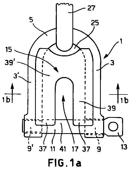
- Fig. 1a shows a plan view of a first preferred embodiment of the shackle of the present invention;
- Fig. 1b shows a front view sectioned along
line 1b-1b of Fig. 1a; - Fig. 1c shows a side view of the shackle of Fig. 1a;
- Fig. 1d shows a partially sectioned front view of the method of hooking of the shackle of Fig. 1a;
- Fig. 2a shows a plan view of a second preferred embodiment of the shackle of the present invention;
- Fig. 2b shows a front view sectioned along
line 2b-2b of Fig. 2a; - Fig. 3a shows a plan view of a third preferred embodiment of the shackle of the present invention;
- Fig. 3b shows a front view sectioned along line 3b-3b of Fig. 3a;
- Fig. 4 shows a plan view of a fourth preferred embodiment of the present invention.
- Fig. 5 shows a plan view of another preferred embodiment of the present invention wherein the support half-ring is not rigid but has a leg which is articulated from the rest of the body.
-
- In Figs. 1a-1d the
shackle 1 comprises an external U-shaped support half-ring formed by twolegs 3 and 3' rigidly connected via anarch 5. - The front terminal section of each
leg 3 and 3' of theshackle 1 definesenlargements 7 and 7' having respective transverse throughholes 9 and 9', distanced yet aligned, wherein a threadedbolt 11 is guided to slide. - The
bolt 11 is mobile between a position of opening of theshackle 1, occupied when thehead 13 is moved away from thehole 9, and a position of closure of the shackle, occupied when thehead 13 hits against the external side wall of thehole 9 and the threaded end of thebolt 11 is inserted in the hole 9'. - The end of the
bolt 11 is threaded so as to screw thebolt 11 to the hole 9', also threaded, in such a way as to guarantee locking of the closure of the shackle. - The
shackle 1 also comprises afork 15 placed inside the support half-ring, whose twolegs 39 and 39' are integral with and parallel to thecorresponding legs 3 and 3' of the support half-ring, and whosemouth 41 is turned on the side of thebolt 11. Thefork 15 is in the form of an insert with a U-shapedinternal side wall 17 dimensioned so as to be inserted simultaneously on a diameter of the two straight sides of the chain link which has to be hooked. - In order to guarantee in every case hooking with resistance to breakage from tensile stress no less than the intrinsic resistance of the chain, the diameter of the
bolt 11 has been made equal to the diameter of chain to be hooked by theshackle 1, but a bolt can likewise be used with even greater diameter. - In order to be able to embrace completely a chain with diameter equal to the diameter of the
bolt 11, also considering that in a standard chain the width of the link is equal to approximately three times its diameter, the U-shapedinternal side wall 17 of theinsert 15 has amouth 41 greater than the diameter of thebolt 11 and depth greater by three times the diameter of thebolt 11. - In the present embodiment the diameter of the
bolt 11 is 10 mm exactly like the diameter of thelink 19 ofchain 21 to be hooked. The opening of themouth 41 of theinternal side wall 17 is 12 mm, while its depth is 32 mm and its height 8 mm. - Naturally the dimensions of the component parts of a shackle in accordance with the present invention may differ from those now described and vary according to the chain which has to be hooked.
- The
insert 15 is attached onto theshackle 1 by means of agroove 23 and respectively 23' which extends from the front end to the rear end of the external side walls of theinsert 15. - The cross section of the
groove 23 and respectively 23' defines a circumference arc with curvature equal to that of theround leg 3 and respectively 3' of the half-ring of theshackle 1. - The
insert 15 is engaged on the half-ring of theshackle 1 by first inserting frontally the rear wall of theinsert 15 in the mouth of the half-ring of theshackle 1 and then pushing with a light pressure thegroove 23 and respectively 23' to slide on the internal side wall of theadjacent leg 3 and respectively 3' of the half-ring of theshackle 1 until the rear end of thegroove 23 and respectively 23' rests on thearch 5 of the half-ring of theshackle 1. - In Fig. 1a each
front end 37 of the two legs of thefork 15 also has a groove, shaped and orientated like thebolt 11 so as to guide its sliding. When thebolt 11 is in the position of closure of the mouth of thefork 15 thesegrooved portions 37 engage on thebolt 11 and thus also allow support of thefork 15. - The introduction of the
insert 15 in the half-ring of theshackle 1 is partially obstructed by theenlargements 7 and 7' for the passage of thebolt 11, but this offers the advantage that, when theinsert 15 is held in position by the legs of the half-ring of theshackle 1 and by thebolt 11, only a very strong action, of intensity greater than the normal stresses caused during use, is capable of removing it. - The rear side wall of the
insert 15 defines with thearch 5 of the shackle 1 aspan 25 for hooking to theshackle 1 the element to be connected to the chain, represented by way of an example by aring 27. - The removable engaging between the
insert 15 and the half-ring of theshackle 1 advantageously allows thering 27 to be hooked preliminarily onto theshackle 1. - As shown in Figs. 1b and 1d, the innermost portion of the
insert 15 has a reduction in thickness to allow insertion of theshackle 1 on the link and consequently lock sliding of the same along thechain 21. - The operation of hooking of the
shackle 1 to thelink 19 of thechain 21 in fact provides, in the first place, for frontal insertion of the mouth of the fork on the diameter of the median point of the straight sides at the rear 29B first and front 29A subsequently of the chain link to be hooked, in such a way that the upper and respectively lower wall of the reducedthickness 31 of the fork hit against the lower arch of theoverlying chain link 35 and respectively on the upper arch of theunderlying chain link 33, thus locking sliding of theshackle 1 along thechain 21. - Subsequently the
bolt 11 is screwed into the corresponding hole 9' to close and lock the closure of the shackle which restrains thelink 19 in its interior. - The bolt of the present invention can be, as in the aforesaid preferred embodiment, of the unlosable type. For this purpose the innermost tip of the threaded portion of the
bolt 11 is widened to hit against the internal side of thehole 9 in the position of maximum opening of the shackle so as to avoid withdrawal of thebolt 11 from thehole 9. - Naturally, for effective hooking, a shackle of appropriate size has to be chosen for each type, that is to say for each diameter of chain.
- To avoid sliding of the shackle along the chain the fork cannot have any proportions whatsoever in relation to the diameter of the chain to be hooked.
- In particular the opening of the mouth of the fork has to be greater or equal to the size of the diameter of the link but smaller by three times this size in order to be able to grip on the overlying and underlying chain links oriented at 90 degrees in relation to the link to be hooked. It is in any case always preferable for the size of the mouth of the fork not to exceed 50% of the value of the diameter of the link to be hooked, to avoid the risk that, with a mouth having a large opening, a slight relative angular rotation between the hooked link, and the links of the chain chained thereto, may cause withdrawal of the fork from the hooked link.
- On the other hand the height of the fork must be smaller than the diameter of the chain to allow the fork itself to be inserted between the lower arch of the chain link above and the upper arch of the chain link below the hooked link.
- Taking into consideration this criterion of compatibility of a chain with a shackle in accordance with the present invention, it is advantageously possible to use the shackle of the present invention for at least two types of chain, that is to say at least also for the link calibrated with a diameter size smaller then that intended for normal use.
- In the case in question of the preferred embodiment described above, for example the
shackle 1 can also be adopted for chains with diameter of 8 mm. - The following preferred embodiments differ from the present one only by the form wherein the fork is provided, therefore, for the sake of brevity, we will omit the description of the other parts of the shackle or of its mode of use, which we will tacitly assume to be the same as those illustrated hitherto.
- In Figs. 2a-b the second preferred embodiment of the present invention differs from the previous one only by the shape of the fork and its attachment to the support half-ring.
- The fork in this case is an
insert 43 with a horseshoe shape and with a smaller diameter compared to the diameter of the support half-ring and spatially oriented like the support half-ring, with the front ends of the twolegs 45 of the fork this time no longer in contact with thebolt 49. - The
insert 43 is fixed to the half-ring by welding between the external side wall of oneleg 45 and the internal side wall of thecorresponding leg 47 of the support half-ring. - The space formed between the arch of the support half-ring and the arch of the
fork 43 is used for inserting the element to be connected to the chain. - Figs. 3a-b show a third preferred embodiment of the present invention wherein the
fork 51 is now presented as moulding of the internal side wall of the support half-ring obtained by die-casting or forging. - From the moulding of the half-ring a
fork 51 is obtained with U-shaped internal side wall and with a height smaller in size compared to the diameter of the support half-ring 53. - The rear side wall of the
fork 51 formed in this way describes, with the arch of the support half-ring 53, anopening 55 for insertion of the element to be connected to the chain. - Fig. 4 illustrates another embodiment of the shackle of the present invention with the fork formed by the moulding of the support half-ring, wherein the two legs of the fork coincide with the
legs 57 of the support half-ring. - In moulding the fork from the support half-ring the arched
rear side wall 65 defines with the internal wall of the arch 59 of the support half-ring aneye 67 for the passage of the element to be connected to the chain. - The U-shaped profile of the support half-ring in this case is modified by performing on the
terminal portion 69 of thelegs 57 of the fork a first bending 71 towards the exterior of the shackle and asecond bending 73, outside of the first, towards the interior of the shackle to widen the mouth of the fork itself and thus allow its insertion on the chain link without impediment by the enlargements for the holes for passage of the bolt. - It is clear that the present description of preferred embodiments must be read purely by way of an indication, the fork in any case being able to assume other shapes not considered here, without thereby departing from the more general principle provided by the present invention.
- The shape and structure of the external support half-ring may also undergo changes, remaining within the sphere of the present invention.
- By way of an example, in Fig. 5, we have illustrated an external support half-
ring structure 75, not rigid but instead jointed. - The half-ring is formed by a
leg 81 wherefrom the arch 89 of the half-ring projects in one piece and joins to theleg 81 to define aneye 91 for the element to be connected to the chain. - The
other leg 77 of the half-ring is now hinged in 79 to the rest of thebody 75 in such a way that, in its rotated position of opening of the shackle, theholes 83 and 83' are moved away and misaligned and the internal wall of the twolegs ring 75 defines a fork to be inserted on the chain link which has to be hooked. - Once the fork has been inserted in the chain link, the
leg 77 is made to rotate into its position of closure of the shackle wherein the two internal sides of theholes 83 and 83' are substantially in contact, aligning for the passage of the threadedbolt 85. - The axis of the
holes 83 and 83' in position of closure of the shackle is not orthogonal to the direction of insertion of the link to be hooked in such a way that the two adjacent links do not obstruct screwing of thebolt 85 in the respective hole 83'. - Unlike the embodiments described previously, in this case it is the rotation of a leg of the half-ring and not the sliding of the bolt which performs closure of the shackle; the bolt here only serves to lock closure of the shackle.
- Finally, according to a possible variant, the
bolt 85 could also be made in the form of a sliding pin pushed by a spring.
Claims (16)
- A shackle to be attached to the link of a chain, of the type comprising an external support half-ring formed by an arch of the half-ring and by two legs of the half-ring which originate from the opposite ends of said arch, each of the two legs having the terminal end widened and provided with a transverse hole which, at least in the position of closure of the shackle, is aligned with the transverse hole of the other one; and a bolt, for closure of the shackle, slidingly supported in the hole of a leg to be inserted in the hole of the other one; characterised in that it also provides inside the support half-ring, a fork shaped element (15), oriented like the external support half-ring, which can be inserted on a diameter of the two straight sides (29A, 29B) of the chain link (19) to be hooked and which is clamped on the hooked chain link (19) by the adjacent links (33, 35) chained to said hooked chain link.
- A shackle to be attached to the link of a chain according to claim 1, characterised in that one leg (77) of the half-ring is supported rotatingly by the rest of the half-ring (75) between a position of opening of the shackle, wherein the two holes (83, 83) of the legs (77, 81) of the half-ring are spaced and misaligned, and a position of closure of the shackle wherein the two holes (83, 83

- A shackle to be attached to the link of a chain according to claim 1, characterised in that the arch (5, 59) of the half-ring and the two legs (3 and 3
- A shackle to be attached to the link of a chain according to any one of the previous claims, characterised in that means for locking closure of the shackle are provided in the form of threading of the end portion of the bolt (11, 49) which can be engaged with threading provided on the corresponding hole (9
- A shackle to be attached to the link of a chain according to any one of the previous claims, characterised in that between the arch of the support half-ring and the rear wall of said fork a span (25, 55, 67, 91) is provided for hooking the element to be connected to the chain to the shackle.
- A shackle to be attached to the link of a chain according to any one of claims 3 to 5, characterised in that the internal side wall of said fork (15, 43, 51) has a U profile.
- A shackle to be attached to the link of a chain according to any one of claims 3 to 6, characterised in that said fork (15) is in the form of an insert which can be engaged with the half-ring of the shackle.
- A shackle to be attached to the link of a chain according to the previous claim, characterised in that said insert (15) has means for removable engaging with the support half-ring, said engaging means being in the form of a groove (23, 23
- A shackle to be attached to the link of a chain according to the previous claim, characterised in that the front wall (37) of each leg (3, 3
- A shackle to be attached to the link of a chain according to any one of claims 3 to 6, characterised in that each leg (45, 45) of said insert (43) is welded to the corresponding leg (47, 47) of the support half-ring.
- A shackle to be attached to the link of a chain according to any one of claims 3 to 5, characterised in that said fork (51) is formed by moulding of the internal wall of the support half-ring.
- A shackle to be attached to the link of a chain according to any one of claims 3 to 5, characterised in that the legs (57, 57) of said fork are in the form of legs of the support half-ring.
- A shackle to be attached to the link of a chain according to the previous claim, characterised in that the end portions of the legs of the fork have a first bending (71) outwards and a second bending (73) outside of the first towards the interior in such a way as to widen the mouth of the fork itself and thus allow its insertion on the chain link without impediment by the enlargements for the holes of passage of the bolt.
- Use of a shackle provided according to any one of the previous claims for hooking any chain whatsoever which complies with the following proportions in relation to the fork:the size of the mouth of the fork is larger or equal to the diameter of the link of the chain but smaller by three times the diameter of the link of the chain, preferably smaller by 1.5 times the diameter of the link of the chain; andthe height of the fork is smaller in size than the diameter of the chain link.
- Method of hooking a shackle provided according to claims 1, 3, 4, 5 and 14 to the link of a chain, comprising the phases of:frontal insertion of the mouth of the fork (15) on the diameter of the median point of the straight sides (29A, 29B) of the link (19) of chain to be hooked, the axial sliding of the shackle along the chain being contained by the adjacent archs of the chain links (33, 35) chained to the hooked chain link (19);closure of the shackle and locking of the closure of the shackle by sliding and screwing of the bolt (11) inside the aligned and spaced holes (9, 9
- Method of hooking a shackle provided according to claims 1, 2, 4, 5 and 14 to the link of a chain, comprising the phases of:frontal insertion of the mouth of the fork on the diameter of the median point of the straight sides of the chain link to be hooked;closure of the shackle by rotation of a leg (77) of the half-ring as far as the position wherein the holes (83, 83
Applications Claiming Priority (2)
| Application Number | Priority Date | Filing Date | Title |
|---|---|---|---|
| ITMI991793 | 1999-08-06 | ||
| IT1999MI001793A IT1313171B1 (en) | 1999-08-06 | 1999-08-06 | GRILLO HANDLE FOR HOOKING ON CHAIN |
Publications (2)
| Publication Number | Publication Date |
|---|---|
| EP1074765A1 true EP1074765A1 (en) | 2001-02-07 |
| EP1074765B1 EP1074765B1 (en) | 2005-11-09 |
Family
ID=11383536
Family Applications (1)
| Application Number | Title | Priority Date | Filing Date |
|---|---|---|---|
| EP00116158A Expired - Lifetime EP1074765B1 (en) | 1999-08-06 | 2000-08-01 | Shackle (clevis) for hooking onto a chain |
Country Status (5)
| Country | Link |
|---|---|
| US (1) | US6282879B1 (en) |
| EP (1) | EP1074765B1 (en) |
| AT (1) | ATE309488T1 (en) |
| DE (1) | DE60023803T2 (en) |
| IT (1) | IT1313171B1 (en) |
Families Citing this family (23)
| Publication number | Priority date | Publication date | Assignee | Title |
|---|---|---|---|---|
| JP2003171916A (en) * | 2001-12-03 | 2003-06-20 | Yutaka Hara | Barrier chain indicator |
| US6955574B2 (en) * | 2004-01-29 | 2005-10-18 | Rogerson L Keith | Shackle pocket buoy |
| US8607209B2 (en) | 2004-02-04 | 2013-12-10 | Bluerisc Inc. | Energy-focused compiler-assisted branch prediction |
| AU301590S (en) * | 2004-11-16 | 2005-05-10 | Tga Trading Pty Ltd | A shackle |
| USD557592S1 (en) | 2006-06-13 | 2007-12-18 | Kerry Frank | Clevis for removing t-posts |
| GB2443943A (en) * | 2006-11-15 | 2008-05-21 | Joy Mm Delaware Inc | Insert for insertion into a chain link |
| US8256981B2 (en) * | 2009-09-01 | 2012-09-04 | Delta Rigging & Tools, Inc. | Thimble with element retaining feature |
| US20110175383A1 (en) * | 2010-01-21 | 2011-07-21 | Segura Victor J | Shackle apparatus |
| US8171715B2 (en) | 2010-01-21 | 2012-05-08 | Useful Products, L.L.C. | Shackle apparatus |
| ES2721261T3 (en) * | 2011-05-05 | 2019-07-30 | Michael Douglas Costa | Shackle or fork mounting accessory for steel cable and synthetic rope end loops |
| GB201403754D0 (en) * | 2014-03-04 | 2014-04-16 | Latchways Plc | Anti-connection device for fall protection apparatus |
| US9416847B2 (en) * | 2014-07-03 | 2016-08-16 | Foley Patents Llc | Capture block assembly for retaining shackles |
| US10400814B2 (en) | 2014-07-16 | 2019-09-03 | Cnh Industrial America Llc | Cable end loop anti-fouling system |
| US10677316B2 (en) | 2015-10-29 | 2020-06-09 | Factor 55, Llc | Clevis mount thimble |
| US10228044B2 (en) | 2015-10-29 | 2019-03-12 | Factor 55, Llc | Splicer thimble for rope |
| AU2016344016B2 (en) | 2015-10-29 | 2020-01-02 | Warn Industries, Inc. | Rigging connector having combination hook and shackle mounting |
| DE102016202782A1 (en) * | 2016-02-23 | 2017-08-24 | Rud Ketten Rieger & Dietz Gmbh U. Co. Kg | Load-bearing component of the stop, lashing and / or lifting technology with a plastic-metal composite system |
| JP2019015345A (en) * | 2017-07-07 | 2019-01-31 | 関西工業株式会社 | Shackle |
| US10604058B1 (en) * | 2018-11-26 | 2020-03-31 | Bnsf Logistics, Llc | Lashing pawl |
| JP7288516B2 (en) * | 2019-10-30 | 2023-06-07 | 株式会社Ihiポールワース | Coupling device |
| AU2021356735B2 (en) * | 2020-10-08 | 2023-04-06 | MercuryPM Pty Ltd | A winch rigging link |
| DE202020106980U1 (en) | 2020-12-03 | 2022-03-09 | Thiele Gmbh & Co Kg | ring fork |
| CN112811003B (en) * | 2020-12-31 | 2023-02-07 | 浙江双友物流器械股份有限公司 | A coil positioning device |
Citations (5)
| Publication number | Priority date | Publication date | Assignee | Title |
|---|---|---|---|---|
| US2259217A (en) * | 1939-07-17 | 1941-10-14 | Stevenson William | Shackle |
| US3583751A (en) * | 1969-03-21 | 1971-06-08 | Aeroquip Corp | Grab link |
| GB1452358A (en) * | 1973-06-07 | 1976-10-13 | Erlau Ag Eisen Drahtwerk | Shackle for chains and the like |
| US4020630A (en) * | 1975-10-17 | 1977-05-03 | Whitehead & Kales Company | Chain adjustment link |
| FR2672358A1 (en) * | 1991-02-04 | 1992-08-07 | Dubois Andre | Shackle with crossed arms |
Family Cites Families (8)
| Publication number | Priority date | Publication date | Assignee | Title |
|---|---|---|---|---|
| US285962A (en) * | 1883-10-02 | Plow-clevis | ||
| US1222997A (en) * | 1916-07-13 | 1917-04-17 | Henry E Rottmer | Shackle or connecting-link. |
| GB112796A (en) * | 1917-01-19 | 1918-01-21 | Peter Hogan | A Safety Pin for Shackles and the like. |
| US3224185A (en) * | 1963-04-16 | 1965-12-21 | Daniel E Grim | Link and shackle insert |
| US3817028A (en) * | 1972-03-29 | 1974-06-18 | H Blackwood | Chain link shackle |
| GB1461407A (en) * | 1973-08-24 | 1977-01-13 | Parsons Controls Ltd | Link component for trawling gear |
| US4134255A (en) * | 1977-02-24 | 1979-01-16 | Columbia Steel Casting Co., Inc. | Drag chain |
| FR2735198B1 (en) * | 1995-06-12 | 1997-08-01 | Wichard | HANDLE-LUG TYPE FITTING PIECE |
-
1999
- 1999-08-06 IT IT1999MI001793A patent/IT1313171B1/en active
-
2000
- 2000-08-01 AT AT00116158T patent/ATE309488T1/en not_active IP Right Cessation
- 2000-08-01 US US09/629,857 patent/US6282879B1/en not_active Expired - Lifetime
- 2000-08-01 EP EP00116158A patent/EP1074765B1/en not_active Expired - Lifetime
- 2000-08-01 DE DE60023803T patent/DE60023803T2/en not_active Expired - Lifetime
Patent Citations (5)
| Publication number | Priority date | Publication date | Assignee | Title |
|---|---|---|---|---|
| US2259217A (en) * | 1939-07-17 | 1941-10-14 | Stevenson William | Shackle |
| US3583751A (en) * | 1969-03-21 | 1971-06-08 | Aeroquip Corp | Grab link |
| GB1452358A (en) * | 1973-06-07 | 1976-10-13 | Erlau Ag Eisen Drahtwerk | Shackle for chains and the like |
| US4020630A (en) * | 1975-10-17 | 1977-05-03 | Whitehead & Kales Company | Chain adjustment link |
| FR2672358A1 (en) * | 1991-02-04 | 1992-08-07 | Dubois Andre | Shackle with crossed arms |
Also Published As
| Publication number | Publication date |
|---|---|
| ATE309488T1 (en) | 2005-11-15 |
| US6282879B1 (en) | 2001-09-04 |
| IT1313171B1 (en) | 2002-06-17 |
| DE60023803T2 (en) | 2006-08-03 |
| EP1074765B1 (en) | 2005-11-09 |
| ITMI991793A1 (en) | 2001-02-06 |
| DE60023803D1 (en) | 2005-12-15 |
| ITMI991793A0 (en) | 1999-08-06 |
Similar Documents
| Publication | Publication Date | Title |
|---|---|---|
| EP1074765A1 (en) | Shackle (clevis) for hooking onto a chain | |
| ES2336671T3 (en) | ROTATING TUBE COUPLING WITH RETAINING MECHANISM. | |
| EP0756472B1 (en) | Device for stabilizing orthopedic anchors | |
| ES2362276T3 (en) | REMOVABLE FIXING OF A CABLE TO A CABLE DRUM. | |
| EP2109723B1 (en) | Wire termination device | |
| CN101069020A (en) | Quick release shackle pin system | |
| US20120201599A1 (en) | Shackle | |
| US6568165B2 (en) | Component which can be used in conjunction with link chains | |
| EP1608580B1 (en) | A chain coupling component | |
| US4095910A (en) | Builders scaffolding joints | |
| ES2902623T3 (en) | Chain Link Fixing Device | |
| ES2220698T3 (en) | ELEMENT OF UNION. | |
| US4759177A (en) | Safety link | |
| AU2012369318C1 (en) | Closure assembly, in particular for tyre skid chains | |
| US6874206B2 (en) | Component for regulating or modifying the effective length of a round steel chain | |
| ES2258195T3 (en) | SPHERICAL SPRING BOLT. | |
| US20080245049A1 (en) | Coupling element for a shackle | |
| WO2018128709A1 (en) | Method and apparatus for retaining shackles using thimble retaining element | |
| NO320221B1 (en) | Lockable chain link | |
| US4275556A (en) | Clevis type connection device | |
| US4418891A (en) | Device for tensioning chains | |
| AU2017100567A4 (en) | A Connecting Assembly | |
| GB2273520A (en) | Scaffolding clamps | |
| NO144810B (en) | FINISHING FOR HINGLE CABLES. | |
| US4592300A (en) | Anchor |
Legal Events
| Date | Code | Title | Description |
|---|---|---|---|
| PUAI | Public reference made under article 153(3) epc to a published international application that has entered the european phase |
Free format text: ORIGINAL CODE: 0009012 |
|
| AK | Designated contracting states |
Kind code of ref document: A1 Designated state(s): AT BE CH CY DE DK ES FI FR GB GR IE IT LI LU MC NL PT SE |
|
| AX | Request for extension of the european patent |
Free format text: AL;LT;LV;MK;RO;SI |
|
| 17P | Request for examination filed |
Effective date: 20010703 |
|
| AKX | Designation fees paid |
Free format text: AT BE CH CY DE DK ES FI FR GB GR IE IT LI LU MC NL PT SE |
|
| 17Q | First examination report despatched |
Effective date: 20030630 |
|
| GRAP | Despatch of communication of intention to grant a patent |
Free format text: ORIGINAL CODE: EPIDOSNIGR1 |
|
| GRAS | Grant fee paid |
Free format text: ORIGINAL CODE: EPIDOSNIGR3 |
|
| GRAA | (expected) grant |
Free format text: ORIGINAL CODE: 0009210 |
|
| AK | Designated contracting states |
Kind code of ref document: B1 Designated state(s): AT BE CH CY DE DK ES FI FR GB GR IE IT LI LU MC NL PT SE |
|
| PG25 | Lapsed in a contracting state [announced via postgrant information from national office to epo] |
Ref country code: AT Free format text: LAPSE BECAUSE OF FAILURE TO SUBMIT A TRANSLATION OF THE DESCRIPTION OR TO PAY THE FEE WITHIN THE PRESCRIBED TIME-LIMIT Effective date: 20051109 Ref country code: CH Free format text: LAPSE BECAUSE OF FAILURE TO SUBMIT A TRANSLATION OF THE DESCRIPTION OR TO PAY THE FEE WITHIN THE PRESCRIBED TIME-LIMIT Effective date: 20051109 Ref country code: NL Free format text: LAPSE BECAUSE OF FAILURE TO SUBMIT A TRANSLATION OF THE DESCRIPTION OR TO PAY THE FEE WITHIN THE PRESCRIBED TIME-LIMIT Effective date: 20051109 Ref country code: LI Free format text: LAPSE BECAUSE OF FAILURE TO SUBMIT A TRANSLATION OF THE DESCRIPTION OR TO PAY THE FEE WITHIN THE PRESCRIBED TIME-LIMIT Effective date: 20051109 Ref country code: FI Free format text: LAPSE BECAUSE OF FAILURE TO SUBMIT A TRANSLATION OF THE DESCRIPTION OR TO PAY THE FEE WITHIN THE PRESCRIBED TIME-LIMIT Effective date: 20051109 Ref country code: BE Free format text: LAPSE BECAUSE OF FAILURE TO SUBMIT A TRANSLATION OF THE DESCRIPTION OR TO PAY THE FEE WITHIN THE PRESCRIBED TIME-LIMIT Effective date: 20051109 |
|
| REG | Reference to a national code |
Ref country code: GB Ref legal event code: FG4D |
|
| REG | Reference to a national code |
Ref country code: CH Ref legal event code: EP |
|
| REG | Reference to a national code |
Ref country code: IE Ref legal event code: FG4D |
|
| REF | Corresponds to: |
Ref document number: 60023803 Country of ref document: DE Date of ref document: 20051215 Kind code of ref document: P |
|
| PG25 | Lapsed in a contracting state [announced via postgrant information from national office to epo] |
Ref country code: GR Free format text: LAPSE BECAUSE OF FAILURE TO SUBMIT A TRANSLATION OF THE DESCRIPTION OR TO PAY THE FEE WITHIN THE PRESCRIBED TIME-LIMIT Effective date: 20060209 Ref country code: DK Free format text: LAPSE BECAUSE OF FAILURE TO SUBMIT A TRANSLATION OF THE DESCRIPTION OR TO PAY THE FEE WITHIN THE PRESCRIBED TIME-LIMIT Effective date: 20060209 Ref country code: SE Free format text: LAPSE BECAUSE OF FAILURE TO SUBMIT A TRANSLATION OF THE DESCRIPTION OR TO PAY THE FEE WITHIN THE PRESCRIBED TIME-LIMIT Effective date: 20060209 |
|
| PG25 | Lapsed in a contracting state [announced via postgrant information from national office to epo] |
Ref country code: ES Free format text: LAPSE BECAUSE OF FAILURE TO SUBMIT A TRANSLATION OF THE DESCRIPTION OR TO PAY THE FEE WITHIN THE PRESCRIBED TIME-LIMIT Effective date: 20060220 |
|
| PG25 | Lapsed in a contracting state [announced via postgrant information from national office to epo] |
Ref country code: PT Free format text: LAPSE BECAUSE OF FAILURE TO SUBMIT A TRANSLATION OF THE DESCRIPTION OR TO PAY THE FEE WITHIN THE PRESCRIBED TIME-LIMIT Effective date: 20060410 |
|
| NLV1 | Nl: lapsed or annulled due to failure to fulfill the requirements of art. 29p and 29m of the patents act | ||
| REG | Reference to a national code |
Ref country code: CH Ref legal event code: PL |
|
| ET | Fr: translation filed | ||
| PG25 | Lapsed in a contracting state [announced via postgrant information from national office to epo] |
Ref country code: IE Free format text: LAPSE BECAUSE OF NON-PAYMENT OF DUE FEES Effective date: 20060801 |
|
| PG25 | Lapsed in a contracting state [announced via postgrant information from national office to epo] |
Ref country code: MC Free format text: LAPSE BECAUSE OF NON-PAYMENT OF DUE FEES Effective date: 20060831 |
|
| PLBE | No opposition filed within time limit |
Free format text: ORIGINAL CODE: 0009261 |
|
| STAA | Information on the status of an ep patent application or granted ep patent |
Free format text: STATUS: NO OPPOSITION FILED WITHIN TIME LIMIT |
|
| 26N | No opposition filed |
Effective date: 20060810 |
|
| REG | Reference to a national code |
Ref country code: IE Ref legal event code: MM4A |
|
| PG25 | Lapsed in a contracting state [announced via postgrant information from national office to epo] |
Ref country code: LU Free format text: LAPSE BECAUSE OF NON-PAYMENT OF DUE FEES Effective date: 20060801 |
|
| PG25 | Lapsed in a contracting state [announced via postgrant information from national office to epo] |
Ref country code: CY Free format text: LAPSE BECAUSE OF FAILURE TO SUBMIT A TRANSLATION OF THE DESCRIPTION OR TO PAY THE FEE WITHIN THE PRESCRIBED TIME-LIMIT Effective date: 20051109 |
|
| PGFP | Annual fee paid to national office [announced via postgrant information from national office to epo] |
Ref country code: GB Payment date: 20090701 Year of fee payment: 10 Ref country code: DE Payment date: 20090831 Year of fee payment: 10 |
|
| GBPC | Gb: european patent ceased through non-payment of renewal fee |
Effective date: 20100801 |
|
| REG | Reference to a national code |
Ref country code: DE Ref legal event code: R119 Ref document number: 60023803 Country of ref document: DE Effective date: 20110301 |
|
| PG25 | Lapsed in a contracting state [announced via postgrant information from national office to epo] |
Ref country code: DE Free format text: LAPSE BECAUSE OF NON-PAYMENT OF DUE FEES Effective date: 20110301 |
|
| PG25 | Lapsed in a contracting state [announced via postgrant information from national office to epo] |
Ref country code: GB Free format text: LAPSE BECAUSE OF NON-PAYMENT OF DUE FEES Effective date: 20100801 |
|
| REG | Reference to a national code |
Ref country code: FR Ref legal event code: PLFP Year of fee payment: 17 |
|
| REG | Reference to a national code |
Ref country code: FR Ref legal event code: PLFP Year of fee payment: 18 |
|
| PGFP | Annual fee paid to national office [announced via postgrant information from national office to epo] |
Ref country code: FR Payment date: 20170616 Year of fee payment: 18 |
|
| PGFP | Annual fee paid to national office [announced via postgrant information from national office to epo] |
Ref country code: IT Payment date: 20170614 Year of fee payment: 18 |
|
| PG25 | Lapsed in a contracting state [announced via postgrant information from national office to epo] |
Ref country code: IT Free format text: LAPSE BECAUSE OF NON-PAYMENT OF DUE FEES Effective date: 20180801 |
|
| PG25 | Lapsed in a contracting state [announced via postgrant information from national office to epo] |
Ref country code: FR Free format text: LAPSE BECAUSE OF NON-PAYMENT OF DUE FEES Effective date: 20180831 |