EP1074754A1 - Flüssigkeitskupplung - Google Patents
Flüssigkeitskupplung Download PDFInfo
- Publication number
- EP1074754A1 EP1074754A1 EP00116213A EP00116213A EP1074754A1 EP 1074754 A1 EP1074754 A1 EP 1074754A1 EP 00116213 A EP00116213 A EP 00116213A EP 00116213 A EP00116213 A EP 00116213A EP 1074754 A1 EP1074754 A1 EP 1074754A1
- Authority
- EP
- European Patent Office
- Prior art keywords
- pump
- turbine
- shell
- core ring
- fluid coupling
- Prior art date
- Legal status (The legal status is an assumption and is not a legal conclusion. Google has not performed a legal analysis and makes no representation as to the accuracy of the status listed.)
- Withdrawn
Links
Images


Classifications
-
- F—MECHANICAL ENGINEERING; LIGHTING; HEATING; WEAPONS; BLASTING
- F16—ENGINEERING ELEMENTS AND UNITS; GENERAL MEASURES FOR PRODUCING AND MAINTAINING EFFECTIVE FUNCTIONING OF MACHINES OR INSTALLATIONS; THERMAL INSULATION IN GENERAL
- F16D—COUPLINGS FOR TRANSMITTING ROTATION; CLUTCHES; BRAKES
- F16D33/00—Rotary fluid couplings or clutches of the hydrokinetic type
- F16D33/18—Details
- F16D33/20—Shape of wheels, blades, or channels with respect to function
Definitions
- This invention relates to an improvement on a fluid coupling for transmitting a rotating torque of a prime mover.
- a fluid coupling has been used as a power transmission coupling for ships, industrial machinery, and automobiles.
- the fluid coupling comprises a pump having an annular pump shell, and a plurality of impellers disposed radially in the pump shell; and a turbine which has an annular turbine shell, and a plurality of runners disposed radially in the turbine shell and which is disposed opposite the pump.
- a working fluid is filled into the pump and the turbine.
- the so constituted fluid coupling has the pump connected to a crankshaft (an input shaft of the fluid coupling) of, for example, a diesel engine as a prime mover, and has the turbine attached to an output shaft disposed coaxially with the input shaft.
- a fluid coupling in which annular core rings for arranging the flow of the working fluid are provided in the pump shell and the turbine shell.
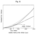
- FIG. 6 shows the relationship between different revolution speeds of the input and output shafts and output torques (transmitted torques) in fluid couplings.
- a dashed line represents the torque transmission characteristics of a conventional fluid coupling.
- the fluid coupling When a fluid coupling with such characteristics is installed in a driving device of a vehicle, the fluid coupling has a drag torque because of its characteristics, if the vehicle is at a stop, the engine is driven, and the transmission gear of a transmission is in mesh, namely, if the input shaft is rotated, while the output shaft is stopped.
- the drag torque generally refers to a transmitted torque when the engine is run at an idle speed (e.g., 500 rpm).
- a fluid coupling shown in FIGS. 7(a), 7(b) and 8 has an annular baffle plate BP disposed between a pump P and a turbine T and attached to an output shaft OS.
- a fluid coupling shown in FIG. 8 has an annular baffle plate BP disposed in an outer peripheral portion of a pump P.
- a working fluid given a rotational force by revolutions of the pump P at a low revolution speed flows into the turbine T from the outer peripheral side under a centrifugal force, as shown in FIG. 7(a).
- the working fluid that has driven the turbine T diminishes in the centrifugal force, approaches a core ring, and flows into the pump P.
- the baffle plate BP disposed between the pump and the turbine exerts minimal effect, and cannot decrease the aforementioned drag torque.
- the working fluid given a rotational force by revolutions of the pump P shown in FIG. 7(b) flows into the turbine T from the outer peripheral side under a centrifugal force.
- the working fluid flowing into the turbine T has a strong centrifugal force, and flows along the inner surface of the turbine shell.
- the working fluid contacts the baffle plate BP when entering the pump P.
- the baffle plate BP acts conspicuously, decreasing the transmitted torque (coupling efficiency).
- the torque transmission characteristics of the fluid coupling illustrated in FIGS. 7(a) and 7(b) are indicated by a one-dot chain line in FIG. 6. As discussed here, the fluid coupling shown in FIGS.
- 7(a) and 7(b) is a low efficiency coupling which not only is unable to reduce the drag torque that should be decreased at a low revolution speed, for example, during idle running of the engine, but also decreases the transmitted torque (coupling efficiency) at a high revolution speed.
- This problem is pronounced in a fluid coupling having core rings provided in the pump shell and the turbine shell.
- the fluid coupling shown in FIG. 8 can reduce a drag torque at a low revolution speed, because the annular baffle plate BP is disposed in the outer peripheral portion of the pump P.
- this fluid coupling drastically decreases a transmitted torque at a high revolution speed.
- the torque transmission characteristics of the fluid-coupling illustrated in FIG. 8 are indicated by a two-dot chain line in FIG. 6. That is, the working fluid given a rotating force by rotations of the pump P flows beside the outer periphery under a centrifugal force. However, when flowing out of the pump P at a peak flow velocity, the working fluid collides with the baffle plate BP to decline in flow velocity, and then flows into the turbine T. Thus, the transmitted torque (coupling efficiency) is sharply decreased during high speed rotations.
- the object of the present invention is to provide a fluid coupling capable of effectively reducing a drag torque without decreasing a transmitted torque.
- a fluid coupling comprising:
- FIG. 1 shows an embodiment of a driving device in which a fluid coupling constituted in accordance with the present invention is disposed between an automobile engine and a friction clutch.
- the driving device in the illustrated embodiment is composed of an internal combustion engine 2 as a prime mover, a fluid coupling 4 constituted in accordance with the invention, and a friction clutch 6.
- the internal combustion engine 2 comprises a diesel engine in the illustrated embodiment, and has an end portion of a crankshaft 21 attached to a later-described pump side of the fluid coupling 4.
- the fluid coupling 4 is disposed in a fluid coupling housing 40 attached by fastening means, such as a bolt 23, to a housing 22 mounted on the diesel engine 2.
- the fluid coupling 4 in the illustrated embodiment includes a pump 41, a turbine 42 disposed opposite the pump 41, and a casing 43 coupled to the pump 41.
- the pump 41 constituting the fluid coupling 4 includes a bowl-shaped pump shell 411 having an annular core ring 411a, and a plurality of impellers 412 disposed radially inside the pump shell 411.
- the pump shell 411 is attached to the casing 43 by bonding means such as welding.
- the casing 43 is mounted by fastening means, such as bolts 441 and nuts 442, to an outer peripheral portion of a drive plate 44 having an inner peripheral portion mounted by a bolt 24 to the crankshaft 21.
- the pump shell 411 of the pump 41 is connected to the crankshaft 21 via the casing 43 and the drive plate 44. Therefore, the crankshaft 21 functions as an input shaft of the fluid coupling 4.
- a starting ring gear 45 meshing with a driving gear of a starter motor (not shown) is mounted on the outer periphery of the drive plate 44.
- the turbine 42 includes a bowl-shaped turbine shell 421 disposed opposite the pump shell 411 of the pump 41 and having an annular core ring 421a, and a plurality of runners 422 disposed radially inside the turbine shell 421.
- the turbine shell 421 is attached by bonding means, such as welding, to a turbine hub 47 splined to an output shaft 46 disposed coaxially with the crankshaft 21 as the input shaft.
- the fluid coupling 4 in the first embodiment illustrated in FIG. 1 has an annular baffle plate 413 mounted, by bonding means such as welding, on an inner periphery of the core ring 411a of the pump 41 at an end portion of the core ring 411a of the pump 41 opposed to the turbine 42.
- the baffle plate 413 is disposed in such a manner as to protrude into a fluid passage formed in the fluid coupling 4.
- the fluid coupling 4 in the illustrated embodiment includes a hydraulic pump 50.
- the hydraulic pump 50 is disposed in a pump housing 52 attached by bonding means, such as bolts 51, to a clutch housing 60 (to be described later on) of the friction clutch 6 mounted on the fluid coupling housing 40.
- the hydraulic pump 50 is adapted to be rotationally driven by a pump hub 48 attached to the pump shell 411 of the pump 41, and supplies a working fluid into the pump 41 and the turbine 42 via a fluid path (not shown).
- the pump hub 48 is supported rotatably by a bearing 490 on a tubular shaft 49 disposed so as to fit around the output shaft 46.
- the friction clutch 6 is disposed in the clutch housing 60 mounted to the fluid coupling housing 40 by a bolt 61.
- the friction clutch 6 in the illustrated embodiment includes a clutch drive plate 62 mounted on the output shaft 46 of the fluid coupling 4; a transmission shaft 63 (an input shaft of a transmission (not shown) in the illustrated embodiment) disposed coaxially with the output shaft 46; a driven plate 66 attached to a clutch hub 64 splined to the transmission shaft 63, and having a clutch facing 65 mounted on an outer peripheral portion thereof; a pressure plate 67 for pressing the driven plate 66 against the clutch drive plate 62; a diaphragm spring 68 for urging the pressure plate 67 toward the clutch drive plate 62; a release bearing 69 which engages with an inner end portion of the diaphragm spring 68 to actuate the diaphragm spring 68 with an intermediate portion of the diaphragm spring 68 as a fulcrum 681; and a clutch release fork
- the diaphragm spring 68 is actuated as indicated by a two-dot chain line in the drawing to release the pushing force imposed on the pressure plate 67. Consequently, power transmission from the clutch drive plate 62 to the driven plate 66 is broken.
- the driving device equipped with the fluid coupling according to the present invention is constituted as described above. Its actions will be explained.
- a driving force which has occurred in the crankshaft 21 (input shaft) of the diesel engine 2 is transmitted to the casing 43 of the fluid coupling 4 via the drive plate 44. Since the casing 43 and the pump shell 411 of the pump 41 are integrally constituted, the pump 41 is rotated by the driving force. Upon rotation of the pump 41, the working fluid in the pump 41 flows toward the outer periphery along the impellers 412 under a centrifugal force, and flows into the turbine 42 as shown by an arrow. The working fluid that has flowed into the turbine 42 flows toward the center, and is then returned to the pump 41 as shown by an arrow.
- FIG. 2(a) shows the flow of the working fluid while the fluid coupling 4 is rotating at a low speed.
- the working fluid given a rotational force by the revolutions of the pump 41 flows into the turbine 42 from the outer peripheral side of the fluid passage under a centrifugal force, as shown by arrows.
- the working fluid that has driven the turbine 42 has a centrifugal force decaying as shown by arrows, approaches the core ring 411a, and flows into the pump 41.
- the annular baffle plate 413 is mounted on the inner periphery in the end portion of the core ring 411a opposed to the turbine 42. Since the working fluid collides with the baffle plate 413 to diminish in flow velocity, the transmitted torque decreases. At a low revolution speed, therefore, the baffle plate 413 acts effectively, and can reduce the drag torque.
- FIG. 2(b) shows the flow of the working fluid while the fluid coupling 4 is rotating at a high speed.
- the working fluid given a rotational force by the revolutions of the pump 41 flows into the turbine 42 from the outer peripheral side of the fluid passage under a centrifugal force, as shown by arrows.
- the working fluid flowing into the turbine 42 has a strong centrifugal force, and flows along the inner surface of the turbine shell 421 as shown by arrows. That is, the high flow velocity working fluid flowing along the inner surface of the turbine shell 421 flows into the pump 41 without undergoing the action of the baffle plate 413, so that no decrease in the transmission efficiency is induced.
- the torque transmission characteristics of the fluid coupling 4 in the first embodiment illustrated in FIGS. 1 and 2 are indicated by a solid line in FIG. 6.
- the fluid coupling 4 in the embodiment shown in FIG. 1 can reduce the drag torque, because the baffle plate 413 acts effectively at a low revolution speed. At a high revolution speed, this fluid coupling 4 does not lead to a decrease in the transmission efficiency, because of minimal influence of the baffle plate 413.
- a fluid coupling 4 in the second embodiment illustrated in FIGS. 3(a) and 3(b) has an annular baffle plate 414 mounted, by bonding means such as welding, on an outer periphery of a core ring 411a of a pump 41 at an end portion of the core ring 411a of the pump 41 opposed to a turbine 42.
- the baffle plate 414 is disposed in such a manner as to protrude into a fluid passage formed in the fluid coupling 4.
- FIG. 3(a) shows the flow of the working fluid while the fluid coupling 4 is rotating at a low speed.
- the working fluid given a rotational force by the revolutions of the pump 41 flows into the turbine 42 as shown by arrows.
- the working fluid given the rotational force by the revolutions of the pump 41 has a low centrifugal force, and the amount of the working fluid flowing beside the inner periphery of the fluid passage is also large.
- the annular baffle plate 414 is mounted on the outer periphery of the core ring 411a.
- the baffle plate 414 acts effectively, and can reduce the drag torque.
- FIG. 3(b) shows the flow of the working fluid while the fluid coupling 4 is rotating at a high speed.
- the working fluid given a rotational force by the revolutions of the pump 41 has a strong centrifugal force, and so flows into the turbine 42 from the outer peripheral side of the fluid passage as shown by arrows.
- the high flow velocity working fluid flowing into the turbine 42 from the outer peripheral side of the fluid passage flows into the turbine 42 without undergoing the action of the baffle plate 414, so that no decrease in the transmission efficiency is induced.
- a fluid coupling 4 in the third embodiment illustrated in FIGS. 4(a) and 4(b) has an annular baffle plate 423 mounted, by bonding means such as welding, on an inner periphery of a core ring 421a of a turbine 42 at an end portion of the core ring 421a of the turbine 42 opposed to a pump 41.
- the baffle plate 423 is disposed in such a manner as to protrude into a fluid passage formed in the fluid coupling 4.
- FIG. 4(a) shows the flow of the working fluid while the fluid coupling 4 is rotating at a low speed.
- the working fluid given a rotational force by the revolutions of the pump 41 flows into the turbine 42 as shown by arrows.
- the working fluid given the rotational force by the revolutions of the pump 41 flows into the turbine 42 from the outer peripheral side of the fluid passage under a centrifugal force as shown by arrows.
- the working fluid that has driven the turbine 42 has a centrifugal force decaying as shown by arrows, approaches the core ring 411a, and flows into the pump 41.
- the annular baffle plate 423 is mounted on the inner periphery of the core ring 421a at the end portion of the core ring 421a opposed to the pump 41.
- the working fluid collides with the baffle plate 423 to have its flow velocity diminished, so that the transmitted torque decreases.
- the baffle plate 423 acts effectively, and can reduce the drag torque.
- FIG. 4(b) shows the flow of the working fluid while the fluid coupling 4 is rotating at a high speed.
- the working fluid given a rotational force by the revolutions of the pump 41 has a strong centrifugal force, and so flows into the turbine 42 from the outer peripheral side of the fluid passage as shown by arrows.
- Such a high flow velocity working fluid flowing into the turbine 42 from the outer peripheral side of the fluid passage flows into the turbine 42 without undergoing the action of the baffle plate 423, so that no decrease in the transmission efficiency is induced.
- a fluid coupling 4 in the fourth embodiment illustrated in FIGS. 5(a) and 5(b) has an annular baffle plate 424 mounted, by bonding means such as welding, on an outer periphery of a core ring 421a of a turbine 42 at an end portion of the core ring 421a of the turbine 42 opposed to a pump 41.
- the baffle plate 424 is disposed in such a manner as to protrude into a fluid passage formed in the fluid coupling 4.
- FIG. 5(a) shows the flow of the working fluid while the fluid coupling 4 is rotating at a low speed.
- the working fluid given a rotational force by the revolutions of the pump 41 flows into the turbine 42 as shown by arrows.
- the working fluid given the rotational force by the revolutions of the pump 41 has a low centrifugal force, and the amount of the working fluid flowing beside the inner periphery of the fluid passage is also large.
- the annular baffle plate 424 is mounted on the outer periphery of the core ring 421a.
- the baffle plate 424 acts effectively, and can reduce the drag torque.
- FIG. 5(b) shows the flow of the working fluid while the fluid coupling 4 is rotating at a high speed.
- the working fluid given a rotational force by the revolutions of the pump 41 has a strong centrifugal force, and so flows into the turbine 42 from the outer peripheral side of the fluid passage as shown by arrows.
- Such a high flow velocity working fluid flowing into the turbine 42 from the outer peripheral side of the fluid passage enters the turbine 42 without undergoing the action of the baffle plate 424, so that no decrease in the transmission efficiency is induced.
- the annular baffle plate is mounted on the inner periphery in the end portion, opposed to the turbine, of the core ring of the pump shell constituting the pump of the fluid coupling.
- the baffle plate acts effectively, and can reduce the drag torque.
- the baffle plate exerts minimal influence, and does not decrease the transmission efficiency.
- the annular baffle plate is mounted on the outer periphery in the end portion, opposed to the turbine, of the core ring of the pump shell constituting the pump of the fluid coupling.
- the annular baffle plate is mounted on the inner periphery in the end portion, opposed to the pump, of the core ring of the turbine shell constituting the turbine of the fluid coupling.
- the annular baffle plate is mounted on the outer periphery in the end portion, opposed to the pump, of the core ring of the turbine shell constituting the turbine of the fluid coupling.
Applications Claiming Priority (2)
| Application Number | Priority Date | Filing Date | Title |
|---|---|---|---|
| JP22146099A JP4420362B2 (ja) | 1999-08-04 | 1999-08-04 | 流体継手 |
| JP22146099 | 1999-08-04 |
Publications (1)
| Publication Number | Publication Date |
|---|---|
| EP1074754A1 true EP1074754A1 (de) | 2001-02-07 |
Family
ID=16767077
Family Applications (1)
| Application Number | Title | Priority Date | Filing Date |
|---|---|---|---|
| EP00116213A Withdrawn EP1074754A1 (de) | 1999-08-04 | 2000-08-03 | Flüssigkeitskupplung |
Country Status (3)
| Country | Link |
|---|---|
| US (1) | US6334307B1 (de) |
| EP (1) | EP1074754A1 (de) |
| JP (1) | JP4420362B2 (de) |
Cited By (1)
| Publication number | Priority date | Publication date | Assignee | Title |
|---|---|---|---|---|
| EP1270979A3 (de) * | 2001-06-29 | 2004-01-21 | Isuzu Motors Limited | Kupplungssteuerungsverfahren |
Families Citing this family (7)
| Publication number | Priority date | Publication date | Assignee | Title |
|---|---|---|---|---|
| DE60132275T2 (de) * | 2000-07-10 | 2008-12-24 | Yutaka Giken Co., Ltd., Hamamatsu | Flüssigkeitskupplung mit Prallplatte |
| US6898931B2 (en) * | 2001-11-16 | 2005-05-31 | Isuzu Motors Limited | Fluid coupling |
| JP4078944B2 (ja) | 2002-10-18 | 2008-04-23 | いすゞ自動車株式会社 | 流体継手 |
| JP4042582B2 (ja) * | 2003-02-07 | 2008-02-06 | いすゞ自動車株式会社 | 流体継手 |
| JP4349044B2 (ja) | 2003-09-05 | 2009-10-21 | いすゞ自動車株式会社 | 流体継手 |
| US9625022B2 (en) * | 2010-07-23 | 2017-04-18 | David J. Goerend | Torque converter with impeller deflector |
| DE102012221435A1 (de) * | 2011-12-23 | 2013-06-27 | Schaeffler Technologies AG & Co. KG | Erweiterte Turbinenschaufel |
Citations (6)
| Publication number | Priority date | Publication date | Assignee | Title |
|---|---|---|---|---|
| NL42758C (de) * | 1900-01-01 | |||
| US2358473A (en) * | 1938-10-29 | 1944-09-19 | Chrysler Corp | Fluid coupling |
| US2389841A (en) * | 1942-10-10 | 1945-11-27 | Jack & Heintz Inc | Fluid coupling |
| US3003318A (en) * | 1957-03-18 | 1961-10-10 | Heyer Don | Fluid coupled transmission mechanism |
| US3277744A (en) * | 1963-12-30 | 1966-10-11 | Ford Motor Co | Transmission |
| JPS5769164A (en) * | 1980-10-16 | 1982-04-27 | Mitsubishi Motors Corp | Torque converter |
Family Cites Families (4)
| Publication number | Priority date | Publication date | Assignee | Title |
|---|---|---|---|---|
| US2216747A (en) * | 1935-09-06 | 1940-10-08 | Gustav A Klimek | Blade construction for fluid power transmitter |
| US2354596A (en) * | 1940-11-25 | 1944-07-25 | Bendix Aviat Corp | Turbotransmission |
| US2691812A (en) * | 1949-04-11 | 1954-10-19 | Packard Motor Car Co | Method of forming fluid turbine elements and the like |
| US4180997A (en) * | 1978-04-17 | 1980-01-01 | Applied Power Inc. | Single piece self-supporting shoe for use in a conduit bender |
-
1999
- 1999-08-04 JP JP22146099A patent/JP4420362B2/ja not_active Expired - Lifetime
-
2000
- 2000-07-31 US US09/629,889 patent/US6334307B1/en not_active Expired - Lifetime
- 2000-08-03 EP EP00116213A patent/EP1074754A1/de not_active Withdrawn
Patent Citations (6)
| Publication number | Priority date | Publication date | Assignee | Title |
|---|---|---|---|---|
| NL42758C (de) * | 1900-01-01 | |||
| US2358473A (en) * | 1938-10-29 | 1944-09-19 | Chrysler Corp | Fluid coupling |
| US2389841A (en) * | 1942-10-10 | 1945-11-27 | Jack & Heintz Inc | Fluid coupling |
| US3003318A (en) * | 1957-03-18 | 1961-10-10 | Heyer Don | Fluid coupled transmission mechanism |
| US3277744A (en) * | 1963-12-30 | 1966-10-11 | Ford Motor Co | Transmission |
| JPS5769164A (en) * | 1980-10-16 | 1982-04-27 | Mitsubishi Motors Corp | Torque converter |
Non-Patent Citations (1)
| Title |
|---|
| PATENT ABSTRACTS OF JAPAN vol. 006, no. 150 (M - 148) 10 August 1982 (1982-08-10) * |
Cited By (3)
| Publication number | Priority date | Publication date | Assignee | Title |
|---|---|---|---|---|
| EP1270979A3 (de) * | 2001-06-29 | 2004-01-21 | Isuzu Motors Limited | Kupplungssteuerungsverfahren |
| US6889804B2 (en) | 2001-06-29 | 2005-05-10 | Isuzu Motors Limited | Clutch control method |
| EP1803959A3 (de) * | 2001-06-29 | 2007-10-31 | Isuzu Motors Limited | Kupplungssteuerungsverfahren |
Also Published As
| Publication number | Publication date |
|---|---|
| JP4420362B2 (ja) | 2010-02-24 |
| US6334307B1 (en) | 2002-01-01 |
| JP2001050309A (ja) | 2001-02-23 |
Similar Documents
| Publication | Publication Date | Title |
|---|---|---|
| US6334307B1 (en) | Fluid coupling | |
| US5685404A (en) | Power transmission system for use with a manual transmission including a torque convertor | |
| JP4193506B2 (ja) | 流体継手 | |
| CN102606706B (zh) | 具有节流板的启动装置 | |
| US7350352B2 (en) | Fluid coupling | |
| JP4042582B2 (ja) | 流体継手 | |
| US6928811B2 (en) | Fluid coupling | |
| US6343528B1 (en) | Lock-up clutch controlling device of vehicle driving device | |
| JP2004156676A (ja) | 小型車両用動力伝達装置 | |
| JP2000266160A (ja) | 流体伝動装置 | |
| JP4314664B2 (ja) | 流体継手装置 | |
| JP4282973B2 (ja) | 小型車両用動力伝達装置 | |
| JP2000249168A (ja) | 流体継手 | |
| JP2003156122A (ja) | 流体継手 | |
| JP2000283184A (ja) | 流体継手 | |
| CN109863332B (zh) | 用于自动变速器的具有单向离合器的变矩器 | |
| JP4729152B2 (ja) | 流体継手装置 | |
| JP2000283185A (ja) | 流体継手 | |
| JP4378792B2 (ja) | 流体継手装置 | |
| JP2003207019A (ja) | 流体継手 | |
| JP2004156678A (ja) | トルクコンバータ |
Legal Events
| Date | Code | Title | Description |
|---|---|---|---|
| PUAI | Public reference made under article 153(3) epc to a published international application that has entered the european phase |
Free format text: ORIGINAL CODE: 0009012 |
|
| AK | Designated contracting states |
Kind code of ref document: A1 Designated state(s): DE FR GB |
|
| AX | Request for extension of the european patent |
Free format text: AL;LT;LV;MK;RO;SI |
|
| 17P | Request for examination filed |
Effective date: 20010727 |
|
| AKX | Designation fees paid |
Free format text: DE FR GB |
|
| RAP1 | Party data changed (applicant data changed or rights of an application transferred) |
Owner name: YUTAKA GIKEN COMPANY LIMITED Owner name: ISUZU MOTORS LIMITED |
|
| 17Q | First examination report despatched |
Effective date: 20040113 |
|
| STAA | Information on the status of an ep patent application or granted ep patent |
Free format text: STATUS: THE APPLICATION IS DEEMED TO BE WITHDRAWN |
|
| 18D | Application deemed to be withdrawn |
Effective date: 20040525 |