EP1074706A2 - Temperature control method for a direct injection engine - Google Patents
Temperature control method for a direct injection engine Download PDFInfo
- Publication number
- EP1074706A2 EP1074706A2 EP00306419A EP00306419A EP1074706A2 EP 1074706 A2 EP1074706 A2 EP 1074706A2 EP 00306419 A EP00306419 A EP 00306419A EP 00306419 A EP00306419 A EP 00306419A EP 1074706 A2 EP1074706 A2 EP 1074706A2
- Authority
- EP
- European Patent Office
- Prior art keywords
- fuel
- temperature
- control device
- emission control
- fuel vapour
- Prior art date
- Legal status (The legal status is an assumption and is not a legal conclusion. Google has not performed a legal analysis and makes no representation as to the accuracy of the status listed.)
- Granted
Links
Images




Classifications
-
- F—MECHANICAL ENGINEERING; LIGHTING; HEATING; WEAPONS; BLASTING
- F02—COMBUSTION ENGINES; HOT-GAS OR COMBUSTION-PRODUCT ENGINE PLANTS
- F02D—CONTROLLING COMBUSTION ENGINES
- F02D41/00—Electrical control of supply of combustible mixture or its constituents
- F02D41/30—Controlling fuel injection
- F02D41/3011—Controlling fuel injection according to or using specific or several modes of combustion
- F02D41/3017—Controlling fuel injection according to or using specific or several modes of combustion characterised by the mode(s) being used
- F02D41/3023—Controlling fuel injection according to or using specific or several modes of combustion characterised by the mode(s) being used a mode being the stratified charge spark-ignited mode
-
- F—MECHANICAL ENGINEERING; LIGHTING; HEATING; WEAPONS; BLASTING
- F02—COMBUSTION ENGINES; HOT-GAS OR COMBUSTION-PRODUCT ENGINE PLANTS
- F02B—INTERNAL-COMBUSTION PISTON ENGINES; COMBUSTION ENGINES IN GENERAL
- F02B23/00—Other engines characterised by special shape or construction of combustion chambers to improve operation
- F02B23/08—Other engines characterised by special shape or construction of combustion chambers to improve operation with positive ignition
- F02B23/10—Other engines characterised by special shape or construction of combustion chambers to improve operation with positive ignition with separate admission of air and fuel into cylinder
- F02B23/104—Other engines characterised by special shape or construction of combustion chambers to improve operation with positive ignition with separate admission of air and fuel into cylinder the injector being placed on a side position of the cylinder
-
- F—MECHANICAL ENGINEERING; LIGHTING; HEATING; WEAPONS; BLASTING
- F02—COMBUSTION ENGINES; HOT-GAS OR COMBUSTION-PRODUCT ENGINE PLANTS
- F02D—CONTROLLING COMBUSTION ENGINES
- F02D41/00—Electrical control of supply of combustible mixture or its constituents
- F02D41/0025—Controlling engines characterised by use of non-liquid fuels, pluralities of fuels, or non-fuel substances added to the combustible mixtures
- F02D41/003—Adding fuel vapours, e.g. drawn from engine fuel reservoir
- F02D41/0032—Controlling the purging of the canister as a function of the engine operating conditions
- F02D41/0035—Controlling the purging of the canister as a function of the engine operating conditions to achieve a special effect, e.g. to warm up the catalyst
-
- F—MECHANICAL ENGINEERING; LIGHTING; HEATING; WEAPONS; BLASTING
- F02—COMBUSTION ENGINES; HOT-GAS OR COMBUSTION-PRODUCT ENGINE PLANTS
- F02D—CONTROLLING COMBUSTION ENGINES
- F02D41/00—Electrical control of supply of combustible mixture or its constituents
- F02D41/02—Circuit arrangements for generating control signals
- F02D41/021—Introducing corrections for particular conditions exterior to the engine
- F02D41/0235—Introducing corrections for particular conditions exterior to the engine in relation with the state of the exhaust gas treating apparatus
- F02D41/024—Introducing corrections for particular conditions exterior to the engine in relation with the state of the exhaust gas treating apparatus to increase temperature of the exhaust gas treating apparatus
- F02D41/025—Introducing corrections for particular conditions exterior to the engine in relation with the state of the exhaust gas treating apparatus to increase temperature of the exhaust gas treating apparatus by changing the composition of the exhaust gas, e.g. for exothermic reaction on exhaust gas treating apparatus
-
- F—MECHANICAL ENGINEERING; LIGHTING; HEATING; WEAPONS; BLASTING
- F02—COMBUSTION ENGINES; HOT-GAS OR COMBUSTION-PRODUCT ENGINE PLANTS
- F02B—INTERNAL-COMBUSTION PISTON ENGINES; COMBUSTION ENGINES IN GENERAL
- F02B17/00—Engines characterised by means for effecting stratification of charge in cylinders
- F02B17/005—Engines characterised by means for effecting stratification of charge in cylinders having direct injection in the combustion chamber
-
- F—MECHANICAL ENGINEERING; LIGHTING; HEATING; WEAPONS; BLASTING
- F02—COMBUSTION ENGINES; HOT-GAS OR COMBUSTION-PRODUCT ENGINE PLANTS
- F02B—INTERNAL-COMBUSTION PISTON ENGINES; COMBUSTION ENGINES IN GENERAL
- F02B75/00—Other engines
- F02B75/12—Other methods of operation
- F02B2075/125—Direct injection in the combustion chamber for spark ignition engines, i.e. not in pre-combustion chamber
-
- F—MECHANICAL ENGINEERING; LIGHTING; HEATING; WEAPONS; BLASTING
- F02—COMBUSTION ENGINES; HOT-GAS OR COMBUSTION-PRODUCT ENGINE PLANTS
- F02D—CONTROLLING COMBUSTION ENGINES
- F02D41/00—Electrical control of supply of combustible mixture or its constituents
- F02D41/02—Circuit arrangements for generating control signals
- F02D41/021—Introducing corrections for particular conditions exterior to the engine
- F02D41/0235—Introducing corrections for particular conditions exterior to the engine in relation with the state of the exhaust gas treating apparatus
- F02D41/027—Introducing corrections for particular conditions exterior to the engine in relation with the state of the exhaust gas treating apparatus to purge or regenerate the exhaust gas treating apparatus
- F02D41/0275—Introducing corrections for particular conditions exterior to the engine in relation with the state of the exhaust gas treating apparatus to purge or regenerate the exhaust gas treating apparatus the exhaust gas treating apparatus being a NOx trap or adsorbent
- F02D41/028—Desulfurisation of NOx traps or adsorbent
-
- F—MECHANICAL ENGINEERING; LIGHTING; HEATING; WEAPONS; BLASTING
- F02—COMBUSTION ENGINES; HOT-GAS OR COMBUSTION-PRODUCT ENGINE PLANTS
- F02M—SUPPLYING COMBUSTION ENGINES IN GENERAL WITH COMBUSTIBLE MIXTURES OR CONSTITUENTS THEREOF
- F02M25/00—Engine-pertinent apparatus for adding non-fuel substances or small quantities of secondary fuel to combustion-air, main fuel or fuel-air mixture
- F02M25/08—Engine-pertinent apparatus for adding non-fuel substances or small quantities of secondary fuel to combustion-air, main fuel or fuel-air mixture adding fuel vapours drawn from engine fuel reservoir
-
- Y—GENERAL TAGGING OF NEW TECHNOLOGICAL DEVELOPMENTS; GENERAL TAGGING OF CROSS-SECTIONAL TECHNOLOGIES SPANNING OVER SEVERAL SECTIONS OF THE IPC; TECHNICAL SUBJECTS COVERED BY FORMER USPC CROSS-REFERENCE ART COLLECTIONS [XRACs] AND DIGESTS
- Y02—TECHNOLOGIES OR APPLICATIONS FOR MITIGATION OR ADAPTATION AGAINST CLIMATE CHANGE
- Y02T—CLIMATE CHANGE MITIGATION TECHNOLOGIES RELATED TO TRANSPORTATION
- Y02T10/00—Road transport of goods or passengers
- Y02T10/10—Internal combustion engine [ICE] based vehicles
- Y02T10/12—Improving ICE efficiencies
Definitions
- the field of the invention relates to fuel vapour purge in direct injection spark ignition engines.
- the engine operates at or near wide-open throttle during stratified air/fuel operation in which the combustion chambers contain stratified layers of different air/fuel mixtures.
- the strata closest to the spark plug contains a stoichiometric mixture or a mixture slightly rich of stoichiometry, and subsequent strata contain progressively leaner mixtures.
- the engine may also operate in a homogeneous mode of operation with a homogeneous mixture of air and fuel generated in the combustion chamber by early injection of fuel into the combustion chamber during its intake stroke. Homogeneous operation may be either lean of stoichiometry, at stoichiometry, or rich of stoichiometry.
- Direct injection engines are also coupled to conventional three-way catalytic converters to reduce CO, HC, and NOx.
- a NOx trap or catalyst is typically coupled downstream of the three-way catalytic converter to further reduce NOx.
- Direct injection engines are also coupled to fuel vapour recovery systems to allow purging of fuel vapours.
- Conventional systems allow fuel vapour purging in the stratified mode only when the catalyst temperature is high enough to convert the unburned hydrocarbons. In other words, since the fuel vapour is inducted with the fresh charge, it forms a homogenous air/fuel mixture. Then, when the fuel is directly injected during the compression stroke to form a stratified mixture, only the stratified fuel burns since the homogenous fuel vapour mixture is too lean. Therefore, unburned fuel vapour may exit the engine cylinder. In some circumstances, to remove these vapours, the catalytic converter may have to be above a certain temperature, known to those skilled in the art as the light-off temperature. Therefore, fuel vapour purging during the stratified mode is restricted until the catalyst has reached this light-off temperature. Such a method is described in U.S. Patent 5,245,975.
- the inventor herein has recognised a disadvantage with the above approach.
- less heat is generated to increase or maintain catalyst or NOx trap temperature.
- the catalyst may not maintain this light-off temperature during certain conditions and purging is only possible in the homogeneous mode, thereby reducing fuel economy and allowable purge time.
- catalyst or NOx trap temperature may fall below the light-off temperature, preventing purge and thereby limiting stratified operation.
- a method for generating heat in an emission control device coupled to an engine having multiple combustion chambers comprising operating in a stratified mode where fuel is injected during a compression stroke of the engine, and purging fuel vapours into the combustion chambers that will pass through the chambers unburned, thereby providing unburned hydrocarbons and excess oxygen to react exothermically and generate heat in the emission control device.
- the fuel vapours are inducted into the cylinder and form a homogeneous mixture that is too lean to combust, even when the engine is operating in a stratified mode.
- These unburned fuel vapours, along with oxygen from the unburned portion of the charge inducted, will react exothermically in the emission control device. This exothermic reaction will generate heat that will increase the emission control device to a desired level.
- this exothermic reaction can be used to maintain the catalyst temperature under conditions where the temperature would otherwise be lower than desired for maximum system efficiency.
- An advantage of the present invention is increased fuel vapour purging during stratified operation.
- Another advantage of the present invention is increased stratified operation and therefore increased fuel economy.
- Yet another advantage of the present invention is decreased emissions.
- Still another advantage of the present invention is that the addition of fuel vapour purge produces minimal, slowly changing, additional torque, allowing smooth transitions into and out of fuel vapour purge operation.
- Direct injection spark ignited internal combustion engine 10 comprising a plurality of combustion chambers, is controlled by electronic engine controller 12.
- Combustion chamber 30 of engine 10 is shown in Figure 1 including combustion chamber walls 32 with piston 36 positioned therein and connected to crankshaft 40.
- piston 30 includes a recess or bowl (not shown) to help in forming stratified charges of air and fuel.
- Combustion chamber 30 is shown communicating with intake manifold 44 and exhaust manifold 48 via respective intake valves 52a and 52b (not shown), and exhaust valves 54a and 54b (not shown).
- Fuel injector 66 is shown directly coupled to combustion chamber 30 for delivering liquid fuel directly therein in proportion to the pulse width of signal fpw received from controller 12 via conventional electronic driver 68. Fuel is delivered to fuel injector 66 by a conventional high pressure fuel system (not shown) including a fuel tank, fuel pumps, and a fuel rail.
- Intake manifold 44 is shown communicating with throttle body 58 via throttle plate 62.
- throttle plate 62 is coupled to electric motor 94 so that the position of throttle plate 62 is controlled by controller 12 via electric motor 94.
- This configuration is commonly referred to as electronic throttle control (ETC] which is also utilised during idle speed control.
- ETC electronic throttle control
- a bypass air passageway is arranged in parallel with throttle plate 62 to control inducted airflow during idle speed control via a throttle control valve positioned within the air passageway.
- Exhaust gas oxygen sensor 76 is shown coupled to exhaust manifold 48 upstream of catalytic converter 70.
- sensor 76 provides signal UEGO to controller 12 which converts signal UEGO into a relative air/fuel ratio ⁇ .
- Signal UEGO is used to advantage during feedback air/fuel control in a conventional manner to maintain average air/fuel at a desired air/fuel ratio.
- Conventional distributorless ignition system 88 provides ignition spark to combustion chamber 30 via spark plug 92 in response to spark advance signal SA from controller 12.
- Controller 12 causes combustion chamber 30 to operate in either a homogeneous air/fuel mode or a stratified air/fuel mode by controlling injection timing.
- controller 12 activates fuel injector 66 during the engine compression stroke so that fuel is sprayed directly into the bowl of piston 36. Stratified air/fuel layers are thereby formed. The strata closest to the spark plug contains a stoichiometric mixture or a mixture slightly rich of stoichiometry, and subsequent strata contain progressively leaner mixtures.
- controller 12 activates fuel injector 66 during the intake stroke so that a substantially homogeneous air/fuel mixture is formed when ignition power is supplied to spark plug 92 by ignition system 88.
- Controller 12 controls the amount of fuel delivered by fuel injector 66 so that the homogeneous air/fuel mixture in chamber 30 can be selected to be at stoichiometry, a value rich of stoichiometry, or a value lean of stoichiometry.
- the stratified air/fuel mixture will always be at a value lean of stoichiometry, the exact air/fuel being a function of the amount of fuel delivered to combustion chamber 30.
- An additional split mode of operation wherein additional fuel is injected during the exhaust stroke while operating in the stratified mode is available.
- An additional split mode of operation wherein additional fuel is injected during the intake stroke while operating in the stratified mode is also available, where a combined homogeneous and split mode is available.
- Nitrogen oxide (NOx) absorbent or trap 72 is shown positioned downstream of catalytic converter 70. NOx trap 72 absorbs NOx when engine 10 is operating lean of stoichiometry. The absorbed NOx is subsequently reacted with HC and catalysed during a NOx purge cycle when controller 12 causes engine 10 to operate in either a rich homogeneous mode or a stoichiometric homogeneous mode.
- NOx Nitrogen oxide
- Controller 12 is shown in Figure 1 as a conventional microcomputer including: microprocessor unit 102, input/output ports 104, an electronic storage medium for executable programs and calibration values, shown as read-only memory chip 106 in this particular example, random access memory 108, keep alive memory 110, and a conventional data bus.
- Controller 12 is shown receiving various signals from sensors coupled to engine 10, in addition to those signals previously discussed, including: measurement of inducted mass air flow (MAP) from mass air flow sensor 100 coupled to throttle body 58; engine coolant temperature (ECT) from temperature sensor 112 coupled to cooling sleeve 114; a profile ignition pickup signal (PIP) from Hall effect sensor 118 coupled to crankshaft 40; throttle position TP from throttle position sensor 120; and absolute Manifold Pressure Signal MAP from sensor 122.
- Engine speed signal RPM is generated by controller 12 from signal PIP in a conventional manner and manifold pressure signal MAP provides an indication of engine load.
- temperature Tcat of catalytic converter 70 and temperature Ttrp of NOx trap 72 are inferred from engine operation as disclosed in U.S. Patent No. 5,414,994, the specification of which is incorporated herein by reference.
- temperature Tcat is provided by temperature sensor 124 and temperature Ttrp is provided by temperature sensor 126.
- Fuel system 130 is coupled to intake manifold 44 via tube 132. Fuel vapours (not shown) generated in fuel system 130 pass through tube 132 and are controlled via purge valve 134. Purge valve 134 receives control signal PRG from controller 12.
- Heat generated in an emission control device can be used to advantage to, for example, rapidly increase temperature of the device to obtain faster light-off during a cold start, control temperature of the device to obtain optimum conversion efficiency, purge the device to remove sulphur contamination, or many other applications where it is advantageous to generate heat in the device.
- Heat is generated in the device by providing unburned fuel vapour (HC) from fuel system 130 along with excess oxygen from lean combustion. This is done by operating the engine in a stratified mode and introducing fuel vapours during the induction stroke, thereby forming a homogeneous fuel vapour mixture at a lean air/fuel ratio that will not support burning of the fuel vapour. Therefore, the fuel vapours pass through the cylinder unburned and react exothermically with the excess oxygen since the overall air/fuel ratio is still lean of stoichiometry.
- HC fuel vapour
- the device can be any emission control device such as a three-way catalytic converter or a NOx trap.
- the upstream device is catalyst 70.
- the upstream device may be trap 72.
- the emission control device In order to maximise the heat generated from fuel vapour and excess oxygen exothermically reacting, the emission control device should be greater than a lower threshold but less than a upper threshold.
- the lower threshold represents the temperature above which exothermic reactions are supported. Note that this threshold temperature for supporting exothermic reactions is different than the light-off temperature, since the light-off temperature is the temperature at which the emission control device reaches high efficiency in converting certain compounds into alternate compounds, thereby reducing certain regulated emissions.
- the upper threshold represents a temperature at which the emission control device reaches high efficiency and no longer needs additional heat. Note that the upper threshold may be equal to the light-off temperature. Also, the upper and lower thresholds are a function of catalyst washcoat chemistry.
- the fuel vapour concentration ( ⁇ f ) is thereby calculated based on total purge flow rate ( m ⁇ p ) from the fuel vapour system, fresh charge measured by the air flow meter ( m ⁇ a ), the relative air/fuel ratio in the exhaust ( ⁇ ), the fuel flow rate from the fuel injectors ( m ⁇ f ), and the stoichiometric air/fuel ratio S.
- the cylinder fuel vapour concentration ( ⁇ fc ) is then based on fuel vapour concentration ( ⁇ f ),total purge flow rate ( m ⁇ p ), and fresh charge measured by the air flow meter (m ⁇ a ).
- the cylinder fuel vapour concentration ( ⁇ fc ) is calculated based on available information and can be used to advantage.
- the calculated cylinder fuel vapour concentration ( ⁇ fc ) can be used to estimate expected emissions using characteristic relationships between cylinder vapour concentration and certain regulated emissions.
- cylinder fuel vapour concentration ( ⁇ fc ) can be used to control many engine control signals such as, for example, ignition timing or injection timing during stratified operation. For example, when operating in a split mode where fuel vapour purge forms the homogenous mixture and direct fuel injection during forms the stratified mixture, the fuel injection timing during the compression stroke to form the stratified fuel is adjusted based on the cylinder vapour concentration to obtain maximum torque.
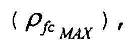
- cylinder fuel vapour concentration is limited by a maximum allowable purge concentration
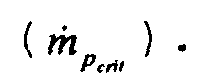
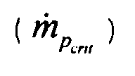
- the calculated cylinder fuel vapour concentration ( ⁇ fc ) can be compared to the maximum allowable purge concentration and used to limit the amount of total purge flow rate ( m ⁇ p ). Allowing the calculated cylinder fuel vapour concentration ( ⁇ fc ) to exceed the maximum allowable, or critical, purge concentration may also cause a change in engine torque.
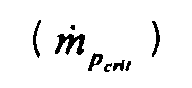
- purge concentration purge valve 134 is controlled to limit total purge flow ( m ⁇ p ) to the maximum allowable, or critical, total purge flow In this way, fuel vapour purge will pass through the cylinder unburned, allowing exotherinic reaction in an emission control device and preventing a change in engine torque.
- cylinder fuel vapour concentration ( ⁇ fc ) exceeds the maximum allowable, or critical, purge concentration then addition engine torque will be produced since some fuel vapours will burn during the engine power stroke.
- other engine control variables are used to keep engine torque constant such as, for example, fresh air charge, ignition timing, exhaust gas recirculation, fuel injection amount, fuel injection timing, and/or variable cam timing.
- rapid engine torque control can be achieved by using ignition timing or fuel injection amount.
- the amount of fuel injection amount adjustment can be determined by estimating an amount of fuel vapour purge that is burned, and this amount subtracted from the normal fuel injection amount.
- fia_c the adjusted fuel injection amount
- fia the normal fuel injection amount (when fuel vapour purge does not exceed the maximum allowable concentration)
- fvp_b the amount of fuel vapour purge burned (determined using predetermined maps relating how far the actual purge concentration exceeds the maximum allowable concentration):
- predetermined characteristic maps relating engine torque to the control variable are used to maintain constant engine torque.
- limiting fuel vapour purge based on a maximum allowable fuel vapour cylinder concentration causes insufficient purging to keep a vapour system from becoming saturated.
- either a split mode or homogenous mode is selected to allow maximum fuel vapour purge, where the fuel vapour purge is burned in the cylinder.
- heat generated by purging fuel vapours during stratified operation can be used to control temperature of the emission control device when the exothermic reaction is taking place.
- the amount of fuel vapour purge which is proportional to exothermic heat creating in the emission control device, can be controlled to maintain a desired emission control device temperature.
- fuel vapour from fuel system 130 can be introduced into the cylinder and pass to the emission control device unburned. The fuel vapour then reacts exothermically in the emission control device, thereby generating heat and increasing temperature of the emission control device. As the temperature of the emission control device approaches the desired value, less fuel vapour purge is introduced, thereby causing temperature of the emission control device to converge to the desired level.
- fuel vapour purge can be allowed to take advantage of a fuel vapour purge opportunity.
- fuel vapour purge can be enabled as long as the emission control device can tolerate increased temperature. In this way, increased fuel vapour purge time is obtained while keeping the emission control device within acceptable temperature limits.
- heat generated by purging fuel vapours during stratified operation can also be used to control temperature of a second emission control device downstream of the emission control device where the exothermic reaction is taking place.
- the heat generated in the upstream device also affects the downstream emission control device temperature and thus can be used to control the temperature of the downstream emission control device.
- fuel vapour purge is controlled to maintain both temperature of the upstream and downstream emission control device.
- fuel vapour is controlled according to both the difference between a desired minimum temperature for the downstream emission control device and actual temperature of the downstream emission control device and the difference between a desired minimum temperature for the upstream emission control device and actual temperature of the upstream emission control device.
- stratified operation By injecting fuel vapours into the engine during stratified operation and allowing them to pass through unburned to maintain emission control device temperature, stratified operation is extended, thus giving a fuel economy benefit. However, if the total amount of fuel used in this operation mode, including fuel vapour and fuel injected to the form strata that are burning, is greater than the amount of fuel that would be used during homogeneous operation to produce equal engine torque, then fuel economy is degraded by continuing stratified operation. Stated another way, when the stratified mode no longer provides a fuel savings because of the additional fuel vapour injected to maintain temperature of the emission control device, the engine air/fuel operating mode is switched to the homogeneous mode thereby maximising fuel economy. In addition, fuel vapour purge during the homogenous mode is still allowed since the additional fuel vapour will burn and produce engine torque.
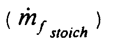
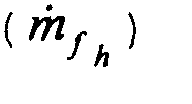
- ⁇ f m p + m f > m f stoich is the amount of fuel necessary during homogenous operation to produce equal engine torque to that produced by actual fuel flow rate from the fuel injectors m ⁇ f during stratified mode.
- m f h m f stoich - ⁇ f m p when fuel vapour purge is continued in the homogenous mode.
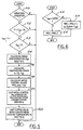
- step 210 a determination is made as to whether engine 10 is operating in a stratified mode where fuel is injected directly into cylinder 30 during a compression stroke.
- step 210 a determination is made as to whether temperature Tcat of catalyst 70 is between threshold values T1 and T2.
- Threshold value T2 represents an upper level above which catalyst 70 is operating a peak efficiency and thus control of temperature (Tcat) is not required.
- Temperature threshold T1 represents a lower level below which catalyst 70 cannot support an exothermic reaction between unburned fuel vapours and excess oxygen.
- the routine continues to step 214, where the fuel vapour concentration ( ⁇ fc ) in the cylinder is calculated, as will be described later herein with particular reference to Figure 3.
- a temperature error (e) is calculated in step 216 based on a desired temperature (Td) of catalyst 70 and the actual temperature (Tcat) of catalyst 70.
- an initial control value (PRG_temp) is calculated based on a function (f) of error (e).
- function (f) represents a proportional, integral, and derivative controller, known to those skilled in the art as a PID controller.
- the initial control value (PRG_temp) is clipped based on the calculated fuel vapour concentration ( ⁇ fc ) in the cylinder, as described later herein with particular reference to Figure 4. This operation prevents the temperature controller from adding too much fuel vapour from fuel system 130 and creating a combustible fuel vapour concentration in the cylinder.
- control signal PRG is calculated based on the clipped value (PRG_c).
- m p g(PRG) where (g) is a predetermine function relating command signal PRG to total flow rate, m ⁇ p .
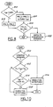
- step 410 a determination is made as to whether purge concentration is greater than the maximum allowable purge concentration to guarantee that the fuel vapours pass the cylinder unburned and react exothermically in catalyst 70. Also, a safety factor, SF is also included.
- the clipped control value (PRG_c) is set to initial control value (PRG_temp) in step 412.
- PRG_temp initial control value
- PRG_MAX the maximum allowable command signal
- step 418 the clipped value (PRG_c) is set equal to the maximum allowable command signal (PRG_MAX).
- step 510 a determination is made as to whether engine 10 is operating in a stratified mode where fuel is injected directly into cylinder 30 during a compression stroke.
- step 512 a determination is made in step 512 as to whether temperature Tcat of catalyst 70 is between threshold values T1 and T2.
- Threshold value T2 represents an upper level above which catalyst 70 is operating a peak efficiency.
- Temperature threshold T1 represents a lower level below which catalyst 70 cannot support an exothermic reaction between unburned fuel vapours and excess oxygen.
- threshold values T1 and T2 can represent threshold temperature of NOx trap 72.
- temperature of catalyst 70 Tcat may be too low to support exothermic reaction due to, for example, washout chemistry.
- NOx trap 72 may be within a temperature range to support exothermic reaction because of it different washcoat formulation. Therefore, in this alternative embodiment the temperature range for allowing purge during stratified operation can is based on temperature of both Tcat and Ttrp.
- step 513 When catalyst temperature Tcat is within this range, or in the alternative embodiment, when trap temperature Ttrp is within the range, the routine continues to step 513, where a determination is made as to whether trap temperature Ttrp is less than control threshold temperature Tt1. If the answer to step 512 is YES, the routine continues to step 513 where the fuel vapour concentration ( ⁇ fc ) in the cylinder is calculated as described previously herein with particular reference to Figure 3.
- a temperature error (e) is calculated in step 516 based on a desired temperature (Td) of NOx trap 72 and the actual temperature (Ttrp) of NOx trap 72.
- an initial control value (PRG_temp) is calculated based on a function (f) of error (e).
- function (f) represents a proportional, integral, and derivative controller, known to those skilled in the art as a PID controller.
- the initial control value (PRG_temp) is clipped based on the calculated fuel vapour concentration ( ⁇ fc ) in the cylinder, as described previously herein with particular reference to Figure 4.
- step 522 clipped control signal (PRG_c) is limited based on temperature (Tcat) of catalyst 70, as described later herein with particular reference to Figure 6 or Figure 8.
- step 610 a determination is made as to whether temperature (Tcat) of catalyst 70 is less than a maximum allowable temperature (TuMAX).
- control signal PRG is calculated based on the clipped value (PRG_c). Otherwise, control signal PRG is calculated based on the clipped value (PRG_c) and a function (f2) of maximum allowable temperature (TuMAX) and temperature (Tcat) of catalyst 70.
- function (f2) represents a proportional, integral, and derivative controller, known to those skilled in the art as a PID controller.
- step 710 a determination is made as to whether engine 10 is operating in a stratified mode where fuel is injected directly into cylinder 30 during a compression stroke.
- step 710 the routine continues to step 514, where the fuel vapour concentration ( ⁇ fc ) in the cylinder is calculated, as described previously herein with particular reference to Figure 3.
- step 712 a determination is made as to whether temperature Tcat of catalyst 70 is between threshold values T1 and T2.
- Threshold value T2 represents an upper level above which catalyst 70 is operating a peak efficiency. Temperature threshold T1 represents a lower level below which catalyst 70 cannot support an exothermic reaction between unburned fuel vapours and excess oxygen.
- a catalyst temperature error (e) is calculated in step 714 based on a desired catalyst temperature (Tdcat) of catalyst 70 and the actual temperature (Tcat) of catalyst 70.
- step 716 a determination is made as to whether temperature Ttrp of NOx trap 72 is between threshold values T1' and T2'.
- Threshold value T2' represents an upper level above which NOx trap 72 is operating a peak efficiency.
- Temperature threshold T1' represents a lower level below which NOx trap 72 cannot support an exothermic reaction between unburned fuel vapours and excess oxygen.
- a trap temperature error (e') is calculated in step 718 based on a desired trap temperature (Tdtrp) of NOx trap 72 and the actual temperature (Ttrp) of NOx trap 72. Otherwise, trap temperature error (e') is set to zero in step 720.
- step 722 from either step 718 or 720, a total error (etot) is calculated from both trap temperature error (e') and catalyst temperature error (e).
- an initial control value (PRG_temp) is calculated based on a function (f) of total error (etot).
- function (f) represents a proportional, integral, and derivative controller, known to those skilled in the art as a PID controller.
- the initial control value (PRG_temp) is clipped based on the calculated fuel vapour concentration ( ⁇ fc ) in the cylinder, as described previously herein with particular reference to Figure 4.
- step 728 clipped control signal (PRG_c) is limited based on temperature (Tcat) of catalyst 70, as described previously herein with particular reference to Figure 6.
- step 740 determines whether temperature Ttrp of NOx trap 72 is between threshold values T1' and T2'.
- trap temperature error (e') is calculated in step 742 based on a desired trap temperature (Tdtrp) of NOx trap 72 and the actual temperature (Ttrp) of NOx trap 72.
- catalyst temperature error (e) is set to zero. Otherwise, trap temperature error (e') is set to zero and catalyst temperature error (e) is set to zero in step 746.
- both emission control device temperatures are maintained above a value representing peak catalyst efficiency using unburned fuel vapour purge.
- step 810 a determination is made as to whether temperature (Tcat) of catalyst 70 is less than a maximum allowable temperature (TuMAX).
- intermediate control signal PRG_S is calculated based on the clipped value (PRG_c).
- intermediate control signal PRG_S is calculated in step 814 based on the clipped value (PRG_c) and a function (f2) of maximum allowable temperature (TuMAX) and temperature (Tcat) of catalyst 70.
- function (f2) represents a proportional, integral, and derivative controller, known to those skilled in the art as a PID controller.
- step 820 a determination is made as to whether intermediate control signal PRG_S is greater than required fuel vapour purge REQ_PRG.
- Required fuel vapour purge REQ_PRG is determined so that fuel system 130 does not become oversaturated with fuel vapours.
- step 820 If the answer to step 820 is NO, then additional fuel vapour purge is required. Since fuel vapour purge cannot be increased in the current mode without increasing engine torque or emission control device temperature, engine 10 is switched to homogenous operation in step 822. In an alternative embodiment, engine 10 is switched a split mode where both a homogeneous mixture and stratified mixture, both of which burn in the engine cylinders, are formed.
- step 910 a determination is made as to whether engine 10 is operating in a stratified mode where fuel is injected directly into cylinder 30 during a compression stroke.
- step 910 a determination is made as to whether temperature Tcat of catalyst 70 is between threshold values T1 and T2.
- Threshold value T2 represents an upper level above which catalyst 70 is operating a peak efficiency and thus control of temperature (Tcat) is not required.
- Temperature threshold T1 represents a lower level below which catalyst 70 cannot support an exothermic reaction between unburned fuel vapours and excess oxygen.
- the routine continues to step 914, where the fuel vapour concentration ( ⁇ fc ) in the cylinder is calculated, as will be described later herein with particular reference to Figure 3.
- a temperature error (e) is calculated in step 916 based on a desired temperature (Td) of catalyst 70 and the actual temperature (Tcat) of catalyst 70.
- an initial control value (PRG_temp) is calculated based on a function (f) of error (e).
- function (f) represents a proportional, integral, and derivative controller, known to those skilled in the art as a PID controller.
- the initial control value (PRG_temp) is clipped based on the calculated fuel vapour concentration ( ⁇ fc ) in the cylinder, as described previously herein with particular reference to Figure 4.
- step 922 a determination is made as to whether clipped value (PRG_c) is less than a required purge value to prevent saturation of fuel system 130. If the answer is YES, then in step 924, stratified operation is discontinues. Thus, engine 10 is operated in homogenous mode and purging is allowed at the required rate. Otherwise, in step 930, control signal PRG is calculated based on the clipped value (PRG_c).
- step 1010 a determination is made as to whether engine 10 is operating in a stratified mode where fuel is injected directly into cylinder 30 during a compression stroke.
- step 1012 a determination is made in step 1012 as to whether temperature Tcat of catalyst 70 is between threshold values T11 and T22.
- Threshold value T22 represents an upper level above which efficiency of catalyst 70 degrades.
- Temperature threshold T11 represents a lower level below which catalyst 70 cannot support an exothermic reaction between unburned fuel vapours and excess oxygen.
- step 1014 determines whether catalyst temperature Tcat is in a lower portion of an allowable purge temperature range defined by T11 and T22, where parameter X represents a predetermined percentage of the allowable purge temperature range. Parameter X is based on engine operating conditions such as, for example, engine fresh air flow.
Landscapes
- Engineering & Computer Science (AREA)
- Chemical & Material Sciences (AREA)
- Combustion & Propulsion (AREA)
- Mechanical Engineering (AREA)
- General Engineering & Computer Science (AREA)
- Chemical Kinetics & Catalysis (AREA)
- Electrical Control Of Air Or Fuel Supplied To Internal-Combustion Engine (AREA)
- Supplying Secondary Fuel Or The Like To Fuel, Air Or Fuel-Air Mixtures (AREA)
Abstract
Description





Claims (10)
- A method for generating heat in an emission control device (70,72) coupled to an engine (10) having multiple combustion chambers (30), the method comprising:operating in a stratified mode where fuel is injected during a compression stroke of the engine;purging fuel vapours into the combustion chambers (30) that will pass through the chambers unburned, thereby providing unburned hydrocarbons and excess oxygen to react exothermically and generate heat in the emission control device (70,72).
- A method as claimed in Claim 1, wherein said fuel vapour purging is performed during an engine start to rapidly increase temperature of the emission control device.
- A method as claimed in Claim 1, wherein said purging is performed when a temperature of the emission control device is less than a predetermined value.
- A method as claimed in Claim 1, wherein said purging is performed when a temperature of the emission control device is within a predetermined range.
- A method as claimed in Claim 4, wherein said predetermined range represents a temperature range where exothermic reactions are possible.
- A method as claimed in Claim 5, wherein said temperature range is based on the emission control device washcoat materials.
- A method as claimed in Claim 1, wherein said fuel vapour purging is performed to increase temperature and desulphate the emission control device.
- A control method for an engine having multiple combustion chambers coupled to an emission control device, the method comprising the steps of:operating in a stratified mode where fuel is injected during a compression stroke of the engine;providing an indication of temperature of the emission control device; andpurging fuel vapours into the combustion chambers when said temperature is below a predetermined threshold, thereby providing unburned hydrocarbons and excess oxygen to react exothermically and increase said temperature.
- A method as claimed in Claim 8 further comprising the step of adjusting an amount of said purged fuel vapours based on said temperature and a desired emission control device temperature.
- A method as claimed in Claim 8, wherein said purging step further comprises purging fuel vapours into the combustion chambers when said temperature is above a preselected threshold, with said preselected threshold is less than said predetermined threshold.
Applications Claiming Priority (2)
| Application Number | Priority Date | Filing Date | Title |
|---|---|---|---|
| US366016 | 1999-08-02 | ||
| US09/366,016 US6233924B1 (en) | 1999-08-02 | 1999-08-02 | Temperature control method for a direct injection engine |
Publications (3)
| Publication Number | Publication Date |
|---|---|
| EP1074706A2 true EP1074706A2 (en) | 2001-02-07 |
| EP1074706A3 EP1074706A3 (en) | 2002-06-19 |
| EP1074706B1 EP1074706B1 (en) | 2004-11-10 |
Family
ID=23441339
Family Applications (1)
| Application Number | Title | Priority Date | Filing Date |
|---|---|---|---|
| EP00306419A Expired - Lifetime EP1074706B1 (en) | 1999-08-02 | 2000-07-27 | Temperature control method for a direct injection engine |
Country Status (3)
| Country | Link |
|---|---|
| US (1) | US6233924B1 (en) |
| EP (1) | EP1074706B1 (en) |
| DE (1) | DE60015665T2 (en) |
Cited By (5)
| Publication number | Priority date | Publication date | Assignee | Title |
|---|---|---|---|---|
| GB2363476A (en) * | 2000-06-13 | 2001-12-19 | Visteon Global Tech Inc | Controlling fuel vapour purging in stratified combustion mode of DISI engine |
| US6553959B2 (en) | 2000-06-13 | 2003-04-29 | Visteon Global Technologies, Inc. | Electronic flow control for a stratified EGR system |
| WO2004001211A1 (en) * | 2002-06-22 | 2003-12-31 | Daimlerchrysler Ag | Method for determining the load of an activated carbon container in a tank ventilation system |
| WO2005124127A1 (en) * | 2004-06-15 | 2005-12-29 | Toyota Jidosha Kabushiki Kaisha | A control device for a purge system of a dual injector fuel system for an internal combustion engine |
| WO2006005457A1 (en) * | 2004-07-10 | 2006-01-19 | Bayerische Motoren Werke Aktiengesellschaft | Method for heating a catalytic converter in the exhaust manifold of an internal combustion engine |
Families Citing this family (3)
| Publication number | Priority date | Publication date | Assignee | Title |
|---|---|---|---|---|
| US6363908B1 (en) * | 2000-08-02 | 2002-04-02 | Ford Global Technologies, Inc. | Method for ensuring combustion of evaporative fuel in a stratified charge engine using multiple fuel injection pulses |
| DE102011080209A1 (en) | 2011-08-01 | 2013-02-07 | Robert Bosch Gmbh | Cutting device for container cases |
| JP6844488B2 (en) * | 2017-10-03 | 2021-03-17 | トヨタ自動車株式会社 | Internal combustion engine control device |
Family Cites Families (11)
| Publication number | Priority date | Publication date | Assignee | Title |
|---|---|---|---|---|
| US5245975A (en) | 1990-11-28 | 1993-09-21 | Toyota Jidosha Kabushiki Kaisha | Direct injection type internal combustion engine |
| US5438967A (en) | 1992-10-21 | 1995-08-08 | Toyota Jidosha Kabushiki Kaisha | Internal combustion device |
| DE4497012T1 (en) | 1993-09-21 | 1996-10-31 | Orbital Eng Australia | Improvements in the catalytic treatment of engine exhaust |
| US5657625A (en) | 1994-06-17 | 1997-08-19 | Mitsubishi Jidosha Kogyo Kabushiki Kaisha | Apparatus and method for internal combustion engine control |
| JP3562016B2 (en) * | 1994-09-06 | 2004-09-08 | マツダ株式会社 | Car lean burn engine |
| JP3509404B2 (en) * | 1996-08-14 | 2004-03-22 | 日産自動車株式会社 | Intake control device for internal combustion engine |
| KR100336549B1 (en) * | 1996-12-16 | 2002-10-25 | 도요다 지도샤 가부시끼가이샤 | Evaporative fuel supply control device of lean-burn internal combustion engine |
| JP3385919B2 (en) * | 1997-07-10 | 2003-03-10 | 日産自動車株式会社 | Evaporative fuel purge control system for internal combustion engine |
| US5998210A (en) * | 1997-10-01 | 1999-12-07 | Ford Global Technologies, Inc. | Method and apparatus for aging a catalyst |
| US5910096A (en) * | 1997-12-22 | 1999-06-08 | Ford Global Technologies, Inc. | Temperature control system for emission device coupled to direct injection engines |
| US5950603A (en) * | 1998-05-08 | 1999-09-14 | Ford Global Technologies, Inc. | Vapor recovery control system for direct injection spark ignition engines |
-
1999
- 1999-08-02 US US09/366,016 patent/US6233924B1/en not_active Expired - Lifetime
-
2000
- 2000-07-27 EP EP00306419A patent/EP1074706B1/en not_active Expired - Lifetime
- 2000-07-27 DE DE60015665T patent/DE60015665T2/en not_active Expired - Lifetime
Cited By (11)
| Publication number | Priority date | Publication date | Assignee | Title |
|---|---|---|---|---|
| GB2363476A (en) * | 2000-06-13 | 2001-12-19 | Visteon Global Tech Inc | Controlling fuel vapour purging in stratified combustion mode of DISI engine |
| US6553959B2 (en) | 2000-06-13 | 2003-04-29 | Visteon Global Technologies, Inc. | Electronic flow control for a stratified EGR system |
| US6561166B2 (en) | 2000-06-13 | 2003-05-13 | Visteon Global Technologies, Inc. | Purge fuel canister measurement method and system |
| GB2363476B (en) * | 2000-06-13 | 2004-08-25 | Visteon Global Tech Inc | Purge fuel canister measurement method and system |
| WO2004001211A1 (en) * | 2002-06-22 | 2003-12-31 | Daimlerchrysler Ag | Method for determining the load of an activated carbon container in a tank ventilation system |
| US7013215B2 (en) | 2002-06-22 | 2006-03-14 | Daimlerchrysler Ag | Method for determining the charge of an activated carbon container in a tank ventilation system |
| WO2005124127A1 (en) * | 2004-06-15 | 2005-12-29 | Toyota Jidosha Kabushiki Kaisha | A control device for a purge system of a dual injector fuel system for an internal combustion engine |
| US7234447B2 (en) | 2004-06-15 | 2007-06-26 | Toyota Jidosha Kabushiki Kaisha | Control device of internal combustion engine |
| US7273043B2 (en) | 2004-06-15 | 2007-09-25 | Toyota Jidosha Kabushiki Kaisha | Control device of internal combustion engine |
| CN1969113B (en) * | 2004-06-15 | 2011-12-28 | 丰田自动车株式会社 | A control device for a purge system of a dual injector fuel system for an internal combustion engine |
| WO2006005457A1 (en) * | 2004-07-10 | 2006-01-19 | Bayerische Motoren Werke Aktiengesellschaft | Method for heating a catalytic converter in the exhaust manifold of an internal combustion engine |
Also Published As
| Publication number | Publication date |
|---|---|
| US6233924B1 (en) | 2001-05-22 |
| EP1074706A3 (en) | 2002-06-19 |
| EP1074706B1 (en) | 2004-11-10 |
| DE60015665D1 (en) | 2004-12-16 |
| DE60015665T2 (en) | 2005-12-01 |
Similar Documents
| Publication | Publication Date | Title |
|---|---|---|
| EP1042594B1 (en) | Temperature control of emission control devices coupled to direct injection engines | |
| US6735937B2 (en) | Engine air and fuel control | |
| US7363915B2 (en) | Method to control transitions between modes of operation of an engine | |
| US6758185B2 (en) | Method to improve fuel economy in lean burn engines with variable-displacement-like characteristics | |
| US6955155B2 (en) | Method for controlling transitions between operating modes of an engine for rapid heating of an emission control device | |
| US6745747B2 (en) | Method for air-fuel ratio control of a lean burn engine | |
| EP1074729B1 (en) | Method for determining cylinder vapour concentration | |
| EP0974746A2 (en) | An exhaust gas purification device for an internal combustion engine | |
| US6715462B2 (en) | Method to control fuel vapor purging | |
| US6574953B1 (en) | NOx purge air/fuel ratio selection | |
| US6477833B2 (en) | Engine exhaust emission control | |
| EP1074706B1 (en) | Temperature control method for a direct injection engine | |
| EP1074726B1 (en) | Engine control with a fuel vapour purge system | |
| US6553757B1 (en) | NOx purge air/fuel ratio selection | |
| US6490855B1 (en) | Fueling control during emission control device purging | |
| EP1074728B1 (en) | Direct injection engine control with a fuel vapor purge system | |
| EP1074725B1 (en) | Control method for an engine with multiple emission control devices | |
| EP1074727B1 (en) | Fuel vapour purge for a direct injection engine | |
| EP1087118B1 (en) | Heat generation method in an emission control device | |
| US6874312B2 (en) | Oxidant storage capacity estimation | |
| US6912842B2 (en) | Oxygen storage capacity estimation | |
| JP2001073913A (en) | Control device for direct injection spark ignition type internal combustion engine | |
| GB2378668A (en) | A method and system for monitoring the efficiency of an exhaust gas treatment device |
Legal Events
| Date | Code | Title | Description |
|---|---|---|---|
| PUAI | Public reference made under article 153(3) epc to a published international application that has entered the european phase |
Free format text: ORIGINAL CODE: 0009012 |
|
| AK | Designated contracting states |
Kind code of ref document: A2 Designated state(s): AT BE CH CY DE DK ES FI FR GB GR IE IT LI LU MC NL PT SE |
|
| AX | Request for extension of the european patent |
Free format text: AL;LT;LV;MK;RO;SI |
|
| PUAL | Search report despatched |
Free format text: ORIGINAL CODE: 0009013 |
|
| AK | Designated contracting states |
Kind code of ref document: A3 Designated state(s): AT BE CH CY DE DK ES FI FR GB GR IE IT LI LU MC NL PT SE |
|
| AX | Request for extension of the european patent |
Free format text: AL;LT;LV;MK;RO;SI |
|
| RIC1 | Information provided on ipc code assigned before grant |
Free format text: 7F 02B 23/10 A, 7F 02D 35/00 B, 7F 02M 25/08 B, 7F 02D 41/02 B |
|
| 17P | Request for examination filed |
Effective date: 20021030 |
|
| AKX | Designation fees paid |
Designated state(s): DE FR GB |
|
| 17Q | First examination report despatched |
Effective date: 20031105 |
|
| GRAP | Despatch of communication of intention to grant a patent |
Free format text: ORIGINAL CODE: EPIDOSNIGR1 |
|
| GRAS | Grant fee paid |
Free format text: ORIGINAL CODE: EPIDOSNIGR3 |
|
| GRAA | (expected) grant |
Free format text: ORIGINAL CODE: 0009210 |
|
| RAP1 | Party data changed (applicant data changed or rights of an application transferred) |
Owner name: FORD GLOBAL TECHNOLOGIES, LLC |
|
| AK | Designated contracting states |
Kind code of ref document: B1 Designated state(s): DE FR GB |
|
| REG | Reference to a national code |
Ref country code: GB Ref legal event code: FG4D |
|
| PGFP | Annual fee paid to national office [announced via postgrant information from national office to epo] |
Ref country code: FR Payment date: 20041123 Year of fee payment: 5 |
|
| REG | Reference to a national code |
Ref country code: IE Ref legal event code: FG4D |
|
| REF | Corresponds to: |
Ref document number: 60015665 Country of ref document: DE Date of ref document: 20041216 Kind code of ref document: P |
|
| PLBE | No opposition filed within time limit |
Free format text: ORIGINAL CODE: 0009261 |
|
| STAA | Information on the status of an ep patent application or granted ep patent |
Free format text: STATUS: NO OPPOSITION FILED WITHIN TIME LIMIT |
|
| ET | Fr: translation filed | ||
| 26N | No opposition filed |
Effective date: 20050811 |
|
| PG25 | Lapsed in a contracting state [announced via postgrant information from national office to epo] |
Ref country code: FR Free format text: LAPSE BECAUSE OF NON-PAYMENT OF DUE FEES Effective date: 20060331 |
|
| REG | Reference to a national code |
Ref country code: FR Ref legal event code: ST Effective date: 20060331 |
|
| PGFP | Annual fee paid to national office [announced via postgrant information from national office to epo] |
Ref country code: GB Payment date: 20120625 Year of fee payment: 13 |
|
| GBPC | Gb: european patent ceased through non-payment of renewal fee |
Effective date: 20130727 |
|
| PG25 | Lapsed in a contracting state [announced via postgrant information from national office to epo] |
Ref country code: GB Free format text: LAPSE BECAUSE OF NON-PAYMENT OF DUE FEES Effective date: 20130727 |
|
| REG | Reference to a national code |
Ref country code: DE Ref legal event code: R082 Ref document number: 60015665 Country of ref document: DE Representative=s name: DOERFLER, THOMAS, DR.-ING., DE |
|
| PGFP | Annual fee paid to national office [announced via postgrant information from national office to epo] |
Ref country code: DE Payment date: 20190617 Year of fee payment: 20 |
|
| REG | Reference to a national code |
Ref country code: DE Ref legal event code: R071 Ref document number: 60015665 Country of ref document: DE |