EP1074396A1 - Stencil printer - Google Patents
Stencil printer Download PDFInfo
- Publication number
- EP1074396A1 EP1074396A1 EP00116409A EP00116409A EP1074396A1 EP 1074396 A1 EP1074396 A1 EP 1074396A1 EP 00116409 A EP00116409 A EP 00116409A EP 00116409 A EP00116409 A EP 00116409A EP 1074396 A1 EP1074396 A1 EP 1074396A1
- Authority
- EP
- European Patent Office
- Prior art keywords
- press roll
- ink
- printing drum
- stencil printer
- printing
- Prior art date
- Legal status (The legal status is an assumption and is not a legal conclusion. Google has not performed a legal analysis and makes no representation as to the accuracy of the status listed.)
- Granted
Links
Images














Classifications
-
- B—PERFORMING OPERATIONS; TRANSPORTING
- B41—PRINTING; LINING MACHINES; TYPEWRITERS; STAMPS
- B41L—APPARATUS OR DEVICES FOR MANIFOLDING, DUPLICATING OR PRINTING FOR OFFICE OR OTHER COMMERCIAL PURPOSES; ADDRESSING MACHINES OR LIKE SERIES-PRINTING MACHINES
- B41L13/00—Stencilling apparatus for office or other commercial use
- B41L13/04—Stencilling apparatus for office or other commercial use with curved or rotary stencil carriers
- B41L13/06—Stencilling apparatus for office or other commercial use with curved or rotary stencil carriers with a single cylinder carrying the stencil
Definitions
- This invention relates to a stencil printer, and more particularly to a stencil printer in which an internal press roll presses the peripheral wall of a printing drum against a back press roll when printing is done.
- a type of a stencil printer comprising a printing drum which has an ink-permeable peripheral wall and is rotated with a stencil master wound around the peripheral wall, a back press roll which presses a printing paper against the printing drum and conveys the printing paper together with the printing drum, and an internal press roll which is provided in the printing drum to be movable back and forth toward and away from the back press roll and pushes the peripheral wall of the printing drum toward the back press roll.
- the internal press roll is supported for rotation about its central axis by a pair of arm members which are rotated about an axis which is parallel to the axis of rotation of the printing drum and offset therefrom.
- the arm members are rotated between a retracted position where the internal press roll is held just in contact with the inner surface of the peripheral wall of the printing drum or away therefrom and a printing position where the internal press roll pushes a part of the peripheral wall of the printing drum toward the back press roll.
- the printing drum with a stencil master wound around the peripheral wall thereof and the back press roll are rotated in opposite directions with a part of the peripheral wall of the printing drum pressed against the back press roll by the internal press roll and a printing paper is fed between the back press roll and the part of the peripheral wall of the printing drum pressed against the back press roll, whereby ink supplied to the inner surface of the peripheral wall of the printing drum is transferred to the printing paper through the stencil master which has been perforated in a pattern of image to be printed, and printing is done.
- the internal press roll urging force is obtained from the rotating force of the printing drum, and accordingly, the internal press roll urging force fluctuates according to the printing speed, the viscosity of ink and the like, which gives rise to a problem that it is difficult to stably obtain a proper printing pressure. That is, as the printing speed increases, the rotational speed of the printing drum increases and the internal press roll urging force increases. As a result, the amount by which the peripheral wall of the printing drum is pushed toward the back press roll increases and the printing pressure increases.
- the ink to be supplied to the printing drum is supplied to the internal press roll while being stirred by an ink agitator which is driven in synchronization with rotation of the printing drum, and accordingly, when the viscosity of the ink increases because of, for instance, a low ambient temperature of the stencil printer, rotating torque of the printing drum is increased and the internal press roll urging force is increased, which results in a high printing pressure.
- a stencil master seat for fixing a stencil master is mounted on the printing drum, and in order to prevent the stencil master seat from being jammed between the internal press roll and the back press roll, the internal press roll must be moved away from the back press roll when the printing drum is rotated to a position where the stencil master seat is opposed to the back press roll. Further also when printing is temporarily interrupted, the internal press roll must be held away from the back press roll. In this case, since the printing drum is kept rotated and the internal press roll is kept urged toward the back press roll, the internal press roll must be moved away from the back press roll overcoming the urging force. As a result, an excessive force acts on the components of the printing drum such as the gear train and deteriorates durability of such components.
- the internal press roll extends in a direction transverse to the direction of movement of the printing paper (in the direction of width of the printing paper), it is necessary to increase dimensional accuracy and assembling accuracy of the components of the stencil printer such as the internal press roll, the members for supporting the internal press roll, the gear train and the like in order to obtain a uniform printing pressure in the direction of width of the printing paper and it has been impossible to obtain a uniform printing pressure in the direction of width of the printing paper after the stencil printer is manufactured. Depending upon the kind of printings, it is sometimes desirable that printing can be done in different densities in the direction of width of the printing paper.
- the primary object of the present invention is to provide a stencil printer in which a desired printing pressure can be easily obtained.
- a stencil printer comprising a printing drum which has an ink-permeable peripheral wall and is rotated about a predetermined axis of rotation with a stencil master wound around the peripheral wall, a back press roll which associates with the printing drum to nip and convey a printing paper, and an internal press roll which is provided in the printing drum to be movable back and forth toward and away from the back press roll and pushes the peripheral wall of the printing drum toward the back press roll, wherein the improvement comprises
- the internal press roll drive means is provided with a means for moving opposite ends of the internal press roll independently of each other.
- the stencil printer further comprises a printing speed setting means for setting the printing speed and the internal press roll drive means changes the distance between the axis of rotation of the printing drum and the second position according to the printing speed set by the printing speed setting means.
- the stencil printer further comprises an ink temperature detecting means which detects the temperature of the ink and the internal press roll drive means changes the distance between the axis of rotation of the printing drum and the second position according to the temperature of the ink detected by the ink temperature detecting means.
- the ink temperature detecting means detects the temperature of the ink through the ambient temperature of the printing drum, the temperature inside the printing drum or the ambient temperature of the stencil printer.
- the stencil printer further comprises an ink temperature input means for manually inputting a temperature of the ink, and the internal press roll drive means changes the distance between the axis of rotation of the printing drum and the second position according to the temperature of the ink input through the ink temperature input means.
- the temperature of the ink be represented by the ambient temperature of the printing drum, the temperature inside the printing drum or the ambient temperature of the stencil printer.
- the stencil printer further comprises an ink viscosity detecting means which detects the viscosity of the ink and the internal press roll drive means changes the distance between the axis of rotation of the printing drum and the second position according to the viscosity of the ink detected by the ink viscosity detecting means.
- the ink viscosity detecting means detects the viscosity of the ink through the electric current supplied to the electric motor for driving the printing drum or to the electric motor for supplying the ink to the printing drum.
- the stencil printer further comprises an ink viscosity input means for manually inputting a viscosity of the ink
- the internal press roll drive means changes the distance between the axis of rotation of the printing drum and the second position according to the viscosity of the ink input through the ink viscosity input means.
- the viscosity of the ink be represented by the electric current supplied to the electric motor for driving the printing drum or to the electric motor for supplying the ink to the printing drum.
- the stencil printer further comprises a wear detecting means which detects the amount of wear of the internal press roll and the internal press roll drive means changes the distance between the axis of rotation of the printing drum and the second position according to the amount of wear of the internal press roll detected by the wear detecting means.
- the wear detecting means detects the amount of wear of the internal press roll on the basis of the cumulative number of times of printing.
- the stencil printer further comprises a wear input means for manually inputting the amount of wear of the internal press roll, and the internal press roll drive means changes the distance between the axis of rotation of the printing drum and the second position according to the amount of wear of the internal press roll input through the wear input means.
- the amount of wear be estimated on the basis of the cumulative number of times of printing.
- the stencil printer further comprises an original type setting means which sets the type of the original, and the internal press roll drive means changes the distance between the distance between the axis of rotation of the printing drum and the second position to the type of the original set by the original type setting means.
- the stencil printer further comprises an original type input means for manually inputting the type of the original, and the internal press roll drive means changes the distance between the axis of rotation of the printing drum and the second position according to the type of the original input through the original type input means.
- the internal press roll drive means comprises
- the rotation control means be a pulse motor.
- the distance between the axis of rotation of the printing drum and the second position can be freely changed, that is, the distance of the internal press roll from the back press roll when the internal press roll is in the second position can be freely changed. Accordingly, the printing pressure can be optimized by changing the distance between the axis of rotation of the printing drum and the second position according to the printing speed, the viscosity of ink and the like.
- the internal press roll drive means is provided with a means for moving opposite ends of the internal press roll independently of each other, the distances between the axis of rotation of the printing drum and the second position at opposite ends of the internal press roll can be made different from each other, whereby the printing pressure can be easily made uniform even if dimensional accuracy and assembling accuracy of the components of the stencil printer are not so high. Further printing can be done in different densities in the direction of width of the printing paper.
- a desired printing pressure can be obtained irrespective of the printing speed.
- a desired printing pressure can be obtained irrespective of the ink temperature.
- a desired printing pressure can be obtained irrespective of the diameter of the internal press roll which changes with wear.
- the internal press roll drive means comprises a support member which supports the internal press roll, a cam member which is in abutment against the support member and is rotated to move up and down the support member, and a rotation control means which controls the amount of rotation of the cam member, the distance between the axis of rotation of the printing drum and the second position can be changed by simply changing the amount of rotation of the cam member and the internal press roll drive means can be simple in structure.
- the rotation control means comprises a pulse motor
- the distance between the axis of rotation of the printing drum and the second position can be easily changed by simply changing the number of pulses supplied to the pulse motor.
- a stencil printer in accordance with an embodiment of the present invention comprises a printing drum 1 which is substantially cylindrical and is supported for rotation about a rotating shaft 2.
- the printing drum 1 has a peripheral wall which is ink-permeable and flexible.
- the peripheral wall of the printing drum 1 is formed by rolling knitting or web of wire, or a perforated rectangular thin sheet into a cylinder having a central axis along the rotating shaft 2.
- the rotating shaft 2 is supported for rotation on a frame 7 and is driven by a printing drum motor (not shown), whereby the printing drum 1 is rotated about the rotating shaft 2.
- the peripheral wall of the printing drum 1 is removed.
- a back press roll 3 is provided in a predetermined position below the printing drum 1.
- the back press roll 3 is provided with a drive shaft (not shown) parallel to the rotating shaft 2 of the printing drum 1.
- the back press roll 3 is held opposed to the printing drum 1 with a gap intervening therebetween.
- the printing drum 1 and the back press roll 3 are rotated in opposite directions. That is, the printing drum 1 is rotated in the clockwise direction as shown by arrow A and the back press roll 3 is rotated in the counterclockwise direction as shown by arrow B.
- An internal press roll 4 is provided in the printing drum 1.
- the internal press roll 4 is formed of an elastic material such as rubber and pushes a part of the peripheral wall of the printing drum 1 toward the back press roll 3 from inside the peripheral wall.
- the internal press roll 4 is supported for rotation at its opposite ends on a pair of base plates 6 which are supported for rotation about a support shaft 5.
- the support shaft 5 is supported on the frame 7 at a distance from the rotating shaft 2 of the printing drum 1 in parallel thereto.
- the internal press roll 4 is driven by the printing drum motor by way of the rotating shaft 2 and a gear train (not shown).
- Each of the base plates 6 is provided with an opening 6a and an eccentric cam 8 which is rotated about the rotating shaft 2 is in engagement with the opening 6a.
- the eccentric cam 8 is formed integrally with a sector gear 9 which is rotated about the rotating shaft 2. Driving force of a pulse motor 10 is transmitted to the sector gear 9 by way of a motor gear 11 and an idler gear 12, whereby the sector gear 9 and the eccentric cam 8 are rotated. Since the eccentric cam 8 is in engagement with the opening 6a of the base plate 6 on each end of the internal press roll 4 as described above, the base plates 6 are rotated about the support shaft 5 as the eccentric cam 8 is rotated and the internal press roll 4 is moved.
- the position of the internal press roll 4 where the internal press roll 4 is held away from the peripheral wall of the printing drum 1 and a gap is formed between the outer surface of the peripheral wall of the printing drum 1 and the back press roll 3 as shown in Figure 1 will be referred to as "the initial position".
- An L-shaped light-shielding plate 13 is mounted on the sector gear 9 and a sensor 14 which is U-shaped in cross-section is disposed in a position where the light-shielding plate 13 is inserted into the sensor 14 to turn on the output of the sensor 14 when the internal press roll 4 is in the initial position.
- the light-shielding plate 13 is away from the sensor 14 and the output of the sensor 14 is turned off.
- the distance of the internal press roll 4 from the rotating shaft 2 of the printing drum 1 when the internal press roll 4 is in the operative position can be changed by changing the amount of rotation of the eccentric cam 8.
- the amount of rotation of the eccentric cam 8 can be changed by changing the number of pulses to be input into the pulse motor 10.
- the pulse motor 10 is provided on each end of the internal press roll 4, and accordingly, by separately controlling the numbers of pulses to be input into the pulse motors 10, the amount of ejection of the internal press roll 4 can be differently controlled at the opposite ends of the internal press roll 4.
- Figure 5 shows the structure of the control means for controlling the amount of rotation of the pulse motor 10.
- the control means 19 comprises a one-chip microcomputer 20, a control panel 30, an in-drum mechanism 40, a drive section 50 and a printing drum drive section 60.
- the one-chip microcomputer 20 comprises a CPU 21, a ROM 22 in which control program is stored, a RAM 23 for storing operating variables of the CPU 21 and the like, a first A/D converter 24 which digitizes the value of an electric current supplied to a printing drum motor for driving the printing drum 1 in order to detect the viscosity of ink on the basis of the digitized value of the electric current supplied to the printing drum motor, a second A/D converter 25 which digitizes the value of an electric current supplied to an ink supply motor to be described later in order to detect the viscosity of ink on the basis of the digitized value of the electric current supplied to the ink supply motor, and a third A/D converter 26 which digitizes the value of an electric signal from a temperature sensor to be described later in order to detect the temperature inside the printing drum 1 on the basis of the digitized value of the electric signal.
- the control panel 30 comprises a start key 31 for starting printing, a stop key 32 for interrupting printing, an ink viscosity setting switch 33 for setting viscosity of ink, an internal press roll gap setting switch 34 for setting the width of the gap between the internal press roll 4 and the doctor roll 18, a temperature setting switch 35 for setting a temperature such as the temperature of environment in which the stencil printer is installed, and an original mode setting switch 36 for setting the kind of the original to be used in printing as an original mode.
- control panel 30 further comprises an LCD panel 37, selection keys 38A to 38D and a verification key 39.
- Various frames are displayed by the LCD panel 37 and the operator can execute desired settings by operating the selection keys 38A to 38D and the verification key 39 under the guidance shown in the frames.
- an internal press roll gap setting frame shown in Figure 8 appears on the LCD panel 37.
- One of the values of the width of the gap between the internal press roll 4 and the doctor roll 18 is selected by operating the selection keys 38A to 38D, and the selected value of the width of the gap is reversed. Then by depressing the verification key 39, the selected value of the width of the gap is verified and the initial frame shown in Figure 6 is displayed again.
- a temperature setting frame shown in Figure 9 appears on the LCD panel 37.
- One of “auto”, “not lower than 30°C”, “20°C - 30°C”, “10°C - 20°C” and “lower than 10°C” is selected by operating the selection keys 38A to 38D, and the selected temperature is reversed. Then by depressing the verification key 39, the selected temperature is verified and the initial frame shown in Figure 6 is displayed again. Though the temperature is set here on the basis of the temperature of environment in which the stencil printer is installed, the operator may measure the temperature inside or around the printing drum 1, and input a temperature on the basis of the measured temperature.
- the in-drum mechanism 40 comprises a temperature sensor 41 which detects the temperature of environment in which the stencil printer is installed, or the temperature inside or around the printing drum 1, and inputs a detecting signal into the third A/D converter 26, an ink viscosity setting switch 42 for setting the viscosity of ink, an internal press roll gap setting switch 43, a position sensor 14 which detects the initial position of the internal press roll 4, an ink sensor 44 which detects the size of an ink swirl on the internal press roll 4, said pulse motor 10, an ink supply motor 45 which drives the ink pump (not shown) to supply ink to the internal press roll 4, and a cumulative number counter 46 which counts the cumulative number of times of printing.
- the ink viscosity setting switch 42 and the internal press roll gap setting switch 43 are provided on a unit for incorporating the printing drum 1 in the stencil printer and are for setting the viscosity of ink and the width of the gap between the internal press roll 4 and the doctor roll 18 as those on the control panel 30.
- the drive section 50 comprises a pulse motor drive circuit 51 for driving the pulse motor 10, an ink supply motor drive circuit 52 for driving the ink supply motor 45, and an ink supply motor current detecting circuit 53 which detects the electric current supplied to the ink supply motor 45 and inputs a detecting signal representing the electric current supplied to the ink supply motor 45 into the second A/D converter 25.
- the printing drum drive section 60 comprises a printing drum motor 61 which drives the printing drum 1, a printing drum motor drive circuit 62 for driving the printing drum motor 61, and a printing drum motor current detecting circuit 63 which detects the electric current supplied to the printing drum motor 61 and inputs a detecting signal representing the electric current supplied to the printing drum motor 61 into the first A/D converter 24.
- FIG 11 is a flow chart for illustrating general operation of the stencil printer of this embodiment.
- the target amount of rotation X by which the pulse motor 10 is to be rotated is first calculated. (step S11) Then the pulse motor 10 is driven on the basis of the calculated target amount of rotation X and the internal press roll 4 is ejected (step S12) and printing is done with the amount of ejection of the internal press roll 4 corresponding to the calculated amount of rotation X of the pulse motor 10 (step S13). After printing is finished, the internal press roll 4 is returned to the initial position. (step S14)
- the pulse motor 10 is rotated in the regular direction, i.e., in the direction in which the internal press roll 4 is pushed toward the back press roll 3 to press the peripheral wall of the printing drum 1 against the back press roll 3.
- step S21 The pulse motor 10 is kept driven until the position sensor 14 is turned off (the light shielding plate 13 is moved from the position where it opposed to the position sensor 14) and the rotation of the pulse motor 10 reaches the target amount of rotation X calculated in step S11.
- Figure 14 is a time chart showing this internal press roll ejecting operation.
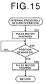
- Figure 15 is a flow chart for illustrating the internal press roll return operation. As shown in Figure 15, in the internal press roll return operation, the pulse motor 10 is reversed to move the internal press roll 4 away from the back press roll 3 until the position sensor 14 is turned on, and then the pulse motor 10 is stopped. (steps S31 to S33)
- Figure 16 is a time chart showing this internal press roll return operation.
- Figure 17 is a flow chart for calculating the target amount of rotation X of the pulse motor 10 on the basis of the temperature of the ink. That is, when the temperature inside or around the printing drum 1 or the temperature of environment in which the stencil printer is installed, and the temperature of ink is low, the viscosity of ink becomes high and the printing density for a given printing pressure becomes low. To the contrast, when the temperature of ink is high, the viscosity of ink becomes low and the printing density for a given printing pressure becomes high.
- the printing pressure is changed by changing the amount of ejection of the internal press roll 4 according to the temperature inside or around the printing drum 1 or the temperature of environment in which the stencil printer is installed detected by the temperature sensor 41 so that the printing density is kept constant irrespective of the temperature of the ink.
- the detecting signal of the temperature sensor 41 is input into the CPU 21 through the third A/D converter 26.
- step S41 As shown in Figure 18, the output of the third A/D converter 26 is proportional to the temperature of the ink.
- the target amount of rotation X is set to 90 steps.
- steps S42 and S43 When the temperature of the ink is not lower than 25°C and lower than 30°C (output of the third A/D converter 26 is not smaller than 50 and smaller than 60), the target amount of rotation X is set to 95 steps.
- step S42, S44 and S45 When the temperature of the ink is not lower than 20°C and lower than 25°C (output of the third A/D converter 26 is not smaller than 40 and smaller than 50), the target amount of rotation X is set to 100 steps.
- step S42, S44, S46 and S47 When the temperature of the ink is not lower than 15°C and lower than 20°C (output of the third A/D converter 26 is not smaller than 30 and smaller than 40), the target amount of rotation X is set to 105 steps.
- step S42, S44, S46, S48 and S49 When the temperature of the ink is lower than 15°C (step S48: NO), the target amount of rotation X is set to 110 steps (step S50).
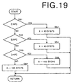
- Figure 19 is a flow chart for calculating the target amount of rotation X of the pulse motor 10 on the basis of the temperature input through the control panel 30.
- the target amount of rotation X is set to 90 steps.
- steps S51 and S52 When the temperature set in the temperature setting frame is not lower than 20°C and lower than 30°C, the target amount of rotation X is set to 95 steps.
- steps S51, S53 and S54 When the temperature set in the temperature setting frame is not lower than 10°C and lower than 20°C, the target amount of rotation X is set to 100 steps.
- step S51, S53, S55 and S56 When the temperature set in the temperature setting frame is lower than 10°C (step S55: NO), the target amount of rotation X is set to 105 steps (step S57).
- the amount of ejection of the internal press roll 4 is increased and the printing pressure increases. Accordingly, the printing pressure is changed according to the viscosity of the ink, which depends upon the temperature of the ink, so that the printing density is kept constant irrespective of the temperature of the ink.
- the temperature of the ink is detected through the temperature inside or around the printing drum 1 or the temperature of environment in which the stencil printer is installed, the temperature of the ink may be directly detected.
- Figure 20 is a flow chart for calculating the target amount of rotation X of the pulse motor 10 on the basis of the viscosity of the ink. That is, as the viscosity of ink becomes higher (the ink is harder), it becomes more difficult to eject the ink through the printing drum 1 and the printing density for a given printing pressure becomes lower. To the contrast, as the viscosity of ink becomes lower, it becomes easier to eject the ink through the printing drum 1 and the printing density for a given printing pressure becomes higher. Accordingly, the printing pressure is changed by changing the amount of ejection of the internal press roll 4 according to the viscosity of the ink so that the printing density is kept constant irrespective of the viscosity of the ink.
- the viscosity of the ink is detected here by way of the amount of electric current supplied to the printing drum motor 61. That is, the ink agitator rod 17 agitates the ink swirl under the driving force of the printing drum motor 61 and accordingly, the driving force required to drive the ink agitator rod 17 changes with the viscosity of the ink. Accordingly, the viscosity of the ink can be estimated on the basis of the amount of electric current supplied to the printing drum motor 61 when agitating the ink, which may be considered to be in proportional to the torque on the ink agitator rod 17.
- the detecting signal of the printing drum motor current detecting circuit 63 is input into the CPU 21 through the first A/D converter 24.
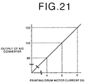
- step S61 As shown in Figure 21, the output of the first A/D converter 24 is proportional to the amount of electric current supplied to the printing drum motor 61.
- the target amount of rotation X is set to 105 steps.
- steps S62 and S63 When the output of the first A/D converter 24 is not smaller than 80 and smaller than 120 (the amount of electric current supplied to the printing drum motor 61 is not smaller than 4A and smaller than 6A), the target amount of rotation X is set to 100 steps.
- step S62, S64 and S65 When the output of the first A/D converter 24 is smaller than 80 (the amount of electric current supplied to the printing drum motor 61 is smaller than 4A) (step S64: NO), the target amount of rotation X is set to 95 steps (step S66).
- Figure 22 is a flow chart for calculating the target amount of rotation X of the pulse motor 10 on the basis of the viscosity of the ink as detected on the basis of the amount of electric current supplied to the ink supply motor 45.
- a variable Y which has been stored in an ink supply interruption processing is input into the CPU 21.
- Figure 23 is a flow chart for illustrating the ink supply interruption processing. As shown in Figure 23, in the ink supply interruption processing, it is determined whether the ink supply motor 45 is rotating.
- step S81 When it is determined that the ink supply motor 45 is rotating, the detecting signal of the ink supply motor current detecting circuit 53 is input into the CPU 21 through the second A/D converter 25 and the value of the output of the second A/D converter 25 is stored in the RAM 23 as the variable Y.
- step S82 As shown in Figure 25, the output of the second A/D converter 25 is proportional to the ink supply motor current.
- step S83 When it is determined that the ink sensor 44 is off, the ink supply motor 45 is turned off (step S84) and the processing returns. When it is determined that the ink sensor 44 is not off, the processing directly returns.
- step S85 When it is determined in step S81 that the ink supply motor 45 is not rotating, it is determined in step S85 whether the output of the ink sensor 44 is on (the output of the ink sensor 44 is turned on when the ink sensor 44 does not detect ink). When it is determined that the output of the ink sensor 44 is on, the processing returns after the ink supply motor 45 started (step S86), and otherwise the processing directly returns.
- Figure 24 is a time chart for the ink supply interruption processing.
- step S72 and S73 When the value of the variable Y is not smaller than 50 and smaller than 100 (the ink supply motor current is not smaller than 0.5A and smaller than 1A), the target amount of rotation X is set to 100 steps.
- step S72, S74 and S75 When the value of the variable Y is smaller than 50 (the ink supply motor current is smaller than 0.5A) (step S74: NO), the target amount of rotation X is set to 95 steps (step S76).
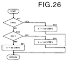
- Figure 26 is a flow chart for calculating the target amount of rotation X of the pulse motor 10 on the basis of the viscosity of ink input through the control panel 30.
- the target amount of rotation X is set to 105 steps.
- steps S91 and S92 When the viscosity of ink set in the ink viscosity setting frame is "soft”, the target amount of rotation X is set to 95 steps.
- steps S91, S93 and S94 When the viscosity of ink set in the ink viscosity setting frame is "normal”, the target amount of rotation X is set to 100 steps. (steps S91, S93 and S95)
- the amount of ejection of the internal press roll 4 is increased and the printing pressure increases. Accordingly, the printing pressure is changed according to the viscosity of ink so that the printing density is kept constant irrespective of the viscosity of ink.
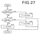
- Figure 27 is a flow chart for calculating the target amount of rotation X of the pulse motor 10 on the basis of the gap between the internal press roll 4 and the doctor roll 18 set by the internal press roll gap setting switch 43. Since the internal press roll 4 is of an elastic material such as rubber, the surface of the internal press roll 4 wears and the gap between the internal press roll 4 and the doctor roll 18 is increased by repeated printing operations. When the gap between the internal press roll 4 and the doctor roll 18 is widened, an excessive amount of ink is deposited on the internal press roll 4 and the printing density becomes higher. In the processing shown in Figure 7, the target amount of rotation X of the pulse motor 10 is calculated so that a desired printing density can be obtained irrespective of the amount of wear of the internal press roll 4.
- the target amount of rotation X is set to 105 steps.
- steps S101 and S102 When the internal press roll gap setting switch 43 is set to "wide gap”, the target amount of rotation X is set to 95 steps.
- steps S101, S103 and S104 When the internal press roll gap setting switch 43 is set to "normal gap”, the target amount of rotation X is set to 100 steps.
- steps S101, S103 and S105 The target amount of rotation X may be calculated on the basis of the gap set in the internal press roll gap setting frame shown in Figure 8.
- Figure 28 is a flow chart for calculating the target amount of rotation X of the pulse motor 10 on the basis of the gap between the internal press roll 4 and the doctor roll 18 estimated on the basis of the cumulative number of times of printing counted by the cumulative number counter 46.
- the target amount of rotation X is set to 90 steps.
- step S111 and S112 When the count of the cumulative number counter 46 is not smaller than 100,000 and smaller than 200,000, which represents that the wear of the internal press roll 4 is relatively large and the gap between the internal press roll 4 and the doctor roll 18 is relatively wide, the target amount of rotation X is set to 95 steps.
- step S111, S113 and S114 When the count of the cumulative number counter 46 is smaller than 100,000, which represents that the wear of the internal press roll 4 is little and the gap between the internal press roll 4 and the doctor roll 18 is narrow, the target amount of rotation X is set to 100 steps. (steps S111, S113 and S115)
- the amount of ejection of the internal press roll 4 is reduced and the printing pressure is lowered.
- the printing density is kept constant irrespective of the amount of wear of the internal press roll 4 or the width of the gap between the internal press roll 4 and the doctor roll 18.
- Figure 29 is a flow chart for calculating the target amount of rotation X of the pulse motor 10 according to the original mode.
- the original for printing various types of originals such as a handwritten original, a copied original, an original for throwaway and the like are used, and a proper printing density differs according to the type of the original.
- the target amount of rotation X of the pulse motor 10 is calculated so that a proper printing density id obtained irrespective of the type of the original or the original mode.
- the target amount of rotation X is set to 105 steps for the purpose of increasing the printing density. (steps S121 and S122)
- the target amount of rotation X is set to 90 steps for the purpose of preventing saturation in detail.
- step S123 and S124 When the original mode set in the original mode setting frame shown in Figure 10 is "throwaway", the target amount of rotation X is set to 110 steps for the purpose of preventing skip in a solid part (steps S125 and S126) When the original mode set in the original mode setting frame shown in Figure 10 is "with picture”, the target amount of rotation X is set to 95 steps for the purpose of properly expressing the gradation. (steps S127 and S128) Otherwise, the target amount of rotation X is set to 100 steps. (step S129)
- the type of the original may be automatically detected in the manner disclosed, for instance, in Japanese Unexamined Patent Publication No. 7(1995)-322061 and the target amount of rotation X may be calculated on the basis of the type of the original.
- the amount of rotation of the pulse motor 10 that is, the amount of ejection of the internal press roll
- the amount of rotation of the pulse motor 10 may be changed according to the printing speed. That is, the printing paper is nipped between the internal press roll 4 and the back press roll 3 and as the printing speed increases, the time for which the printing paper is nipped between the internal press roll 4 and the back press roll 3 is shortened and the amount of ink transferred to the printing paper is reduced. That is, the printing density fluctuates with the printing speed.
- the amount of ejection of the internal press roll 4 according to the printing speed, the printing density can be stabilized irrespective of the printing speed.
- the printing speed is changed in two speeds, one corresponding to 80rpm of the printing drum 1 and the other corresponding to 120rpm of the printing drum 1, and the nipping length of the printing paper (by which the printing paper is nipped between the internal press roll 4 and the back press roll 3 in the direction of conveyance of the printing paper) is 10mm
- the conveying speed of the printing paper is 2.667 ⁇ Rmm/sec in the case of the printing speed of 80rpm and 4.000 ⁇ Rmm/sec in the case of the printing speed of 120rpm.
- the nipping length can be reduced by reducing the amount of ejection of the internal press roll 4 or the amount of rotation of the pulse motor 10. That is, by reducing the amount of ejection of the internal press roll 4 so that the nipping length becomes 6.667mm when the printing speed is 80rpm, the nipping time can be substantially equalized to that when the printing speed is 120rpm.
- the amount of ink transferred to the printing paper can be substantially constant and the printing density can be substantially constant irrespective of the printing speed.
- the amount of rotation of the pulse motor 10 that is, the amount of ejection of the internal press roll
- the amount of rotation of the pulse motor 10 may be changed to user liking.
- the printed image can be in a density to the user liking.
- the printing pressure can be easily made uniform even if dimensional accuracy and assembling accuracy of the components of the stencil printer are not so high. Further printing can be done in different densities in the direction of width of the printing paper.
- the system may be arranged so that the amount of ejection of the internal press roll 4 cannot be differently set at the opposite ends of the internal press roll 4.
- the amount of ejection of the internal press roll 4 is changed by use of the pulse motor 10 and the eccentric cam 8, other various mechanism may be used.
Landscapes
- Inking, Control Or Cleaning Of Printing Machines (AREA)
Abstract
Description
- This invention relates to a stencil printer, and more particularly to a stencil printer in which an internal press roll presses the peripheral wall of a printing drum against a back press roll when printing is done.
- There has been known a type of a stencil printer comprising a printing drum which has an ink-permeable peripheral wall and is rotated with a stencil master wound around the peripheral wall, a back press roll which presses a printing paper against the printing drum and conveys the printing paper together with the printing drum, and an internal press roll which is provided in the printing drum to be movable back and forth toward and away from the back press roll and pushes the peripheral wall of the printing drum toward the back press roll. See, for instance, Japanese Unexamined Patent Publication No. 1(1989)-204781. In the stencil printer of this type, the internal press roll is supported for rotation about its central axis by a pair of arm members which are rotated about an axis which is parallel to the axis of rotation of the printing drum and offset therefrom. The arm members are rotated between a retracted position where the internal press roll is held just in contact with the inner surface of the peripheral wall of the printing drum or away therefrom and a printing position where the internal press roll pushes a part of the peripheral wall of the printing drum toward the back press roll. The printing drum with a stencil master wound around the peripheral wall thereof and the back press roll are rotated in opposite directions with a part of the peripheral wall of the printing drum pressed against the back press roll by the internal press roll and a printing paper is fed between the back press roll and the part of the peripheral wall of the printing drum pressed against the back press roll, whereby ink supplied to the inner surface of the peripheral wall of the printing drum is transferred to the printing paper through the stencil master which has been perforated in a pattern of image to be printed, and printing is done.
- Further, there has been proposed, as disclosed in Japanese Unexamined Patent Publication No. 3(1991)-254984, a stencil printer in which the internal press roll is driven by way of a gear train to rotate in synchronization with the printing drum and the arm members are rotated between the retracted position and the printing position under force which acts on the internal press roll by way of the gear train. In this stencil printer, the internal press roll is not rotated by way of friction between the internal press roll and the peripheral wall of the printing drum with ink intervening therebetween but is actively rotated by way of the gear train in synchronization with the printing drum at a predetermined speed ratio to the printing drum so that the degree of squeezing action between the internal press roll and the peripheral wall of the printing drum is stabilized.
- Further, as disclosed in Japanese Unexamined Patent Publication No. 8(1996)-207416, there has been proposed a stencil printer in which the printing pressure is optimized by controlling flow of force transmitted to the internal press roll through the gear train, and thereby controlling the amount by which the internal press roll pushes the peripheral wall of the printing drum toward the back press roll.
- However, in such a stencil printer where the internal press roll is driven in synchronization with rotation of the printing drum, the internal press roll urging force is obtained from the rotating force of the printing drum, and accordingly, the internal press roll urging force fluctuates according to the printing speed, the viscosity of ink and the like, which gives rise to a problem that it is difficult to stably obtain a proper printing pressure. That is, as the printing speed increases, the rotational speed of the printing drum increases and the internal press roll urging force increases. As a result, the amount by which the peripheral wall of the printing drum is pushed toward the back press roll increases and the printing pressure increases. Further, the ink to be supplied to the printing drum is supplied to the internal press roll while being stirred by an ink agitator which is driven in synchronization with rotation of the printing drum, and accordingly, when the viscosity of the ink increases because of, for instance, a low ambient temperature of the stencil printer, rotating torque of the printing drum is increased and the internal press roll urging force is increased, which results in a high printing pressure.
- Further, a stencil master seat for fixing a stencil master is mounted on the printing drum, and in order to prevent the stencil master seat from being jammed between the internal press roll and the back press roll, the internal press roll must be moved away from the back press roll when the printing drum is rotated to a position where the stencil master seat is opposed to the back press roll. Further also when printing is temporarily interrupted, the internal press roll must be held away from the back press roll. In this case, since the printing drum is kept rotated and the internal press roll is kept urged toward the back press roll, the internal press roll must be moved away from the back press roll overcoming the urging force. As a result, an excessive force acts on the components of the printing drum such as the gear train and deteriorates durability of such components.
- Since the internal press roll extends in a direction transverse to the direction of movement of the printing paper (in the direction of width of the printing paper), it is necessary to increase dimensional accuracy and assembling accuracy of the components of the stencil printer such as the internal press roll, the members for supporting the internal press roll, the gear train and the like in order to obtain a uniform printing pressure in the direction of width of the printing paper and it has been impossible to obtain a uniform printing pressure in the direction of width of the printing paper after the stencil printer is manufactured. Depending upon the kind of printings, it is sometimes desirable that printing can be done in different densities in the direction of width of the printing paper.
- In view of the foregoing observations and description, the primary object of the present invention is to provide a stencil printer in which a desired printing pressure can be easily obtained.
- In accordance with the present invention, there is provided a stencil printer comprising a printing drum which has an ink-permeable peripheral wall and is rotated about a predetermined axis of rotation with a stencil master wound around the peripheral wall, a back press roll which associates with the printing drum to nip and convey a printing paper, and an internal press roll which is provided in the printing drum to be movable back and forth toward and away from the back press roll and pushes the peripheral wall of the printing drum toward the back press roll, wherein the improvement comprises
- an internal press roll drive means which moves back and forth the internal press roll between a first position where the internal press roll is held away from the back press roll and a second position at a distance from the first position toward the back press roll and is able to freely change the distance between the axis of rotation of the printing drum and the second position.
-
- It is preferred that the internal press roll drive means is provided with a means for moving opposite ends of the internal press roll independently of each other.
- It is preferred that the stencil printer further comprises a printing speed setting means for setting the printing speed and the internal press roll drive means changes the distance between the axis of rotation of the printing drum and the second position according to the printing speed set by the printing speed setting means.
- Further it is preferred that the stencil printer further comprises an ink temperature detecting means which detects the temperature of the ink and the internal press roll drive means changes the distance between the axis of rotation of the printing drum and the second position according to the temperature of the ink detected by the ink temperature detecting means.
- In this case, it is preferred that the ink temperature detecting means detects the temperature of the ink through the ambient temperature of the printing drum, the temperature inside the printing drum or the ambient temperature of the stencil printer.
- Further it is preferred that the stencil printer further comprises an ink temperature input means for manually inputting a temperature of the ink, and the internal press roll drive means changes the distance between the axis of rotation of the printing drum and the second position according to the temperature of the ink input through the ink temperature input means.
- In this case, it is preferred that the temperature of the ink be represented by the ambient temperature of the printing drum, the temperature inside the printing drum or the ambient temperature of the stencil printer.
- Further, it is preferred that the stencil printer further comprises an ink viscosity detecting means which detects the viscosity of the ink and the internal press roll drive means changes the distance between the axis of rotation of the printing drum and the second position according to the viscosity of the ink detected by the ink viscosity detecting means.
- In this case, it is preferred that the ink viscosity detecting means detects the viscosity of the ink through the electric current supplied to the electric motor for driving the printing drum or to the electric motor for supplying the ink to the printing drum.
- Further it is preferred that the stencil printer further comprises an ink viscosity input means for manually inputting a viscosity of the ink, and the internal press roll drive means changes the distance between the axis of rotation of the printing drum and the second position according to the viscosity of the ink input through the ink viscosity input means.
- In this case, it is preferred that the viscosity of the ink be represented by the electric current supplied to the electric motor for driving the printing drum or to the electric motor for supplying the ink to the printing drum.
- Further it is preferred that the stencil printer further comprises a wear detecting means which detects the amount of wear of the internal press roll and the internal press roll drive means changes the distance between the axis of rotation of the printing drum and the second position according to the amount of wear of the internal press roll detected by the wear detecting means.
- In this case, it is preferred that the wear detecting means detects the amount of wear of the internal press roll on the basis of the cumulative number of times of printing.
- Further it is preferred that the stencil printer further comprises a wear input means for manually inputting the amount of wear of the internal press roll, and the internal press roll drive means changes the distance between the axis of rotation of the printing drum and the second position according to the amount of wear of the internal press roll input through the wear input means.
- In this case, it is preferred that the amount of wear be estimated on the basis of the cumulative number of times of printing.
- Further it is preferred that the stencil printer further comprises an original type setting means which sets the type of the original, and the internal press roll drive means changes the distance between the distance between the axis of rotation of the printing drum and the second position to the type of the original set by the original type setting means.
- Further it is preferred that the stencil printer further comprises an original type input means for manually inputting the type of the original, and the internal press roll drive means changes the distance between the axis of rotation of the printing drum and the second position according to the type of the original input through the original type input means.
- Further, it is preferred that the internal press roll drive means comprises
- a support member which supports opposite ends of the internal press roll and is rotatable about a predetermined axis of rotation,
- a cam member which is in abutment against the support member and is rotated to move up and down the support member, and
- a rotation control means which controls the amount of rotation of the cam member.
-
- It is preferred that the rotation control means be a pulse motor.
- In the stencil printer of the present invention, the distance between the axis of rotation of the printing drum and the second position can be freely changed, that is, the distance of the internal press roll from the back press roll when the internal press roll is in the second position can be freely changed. Accordingly, the printing pressure can be optimized by changing the distance between the axis of rotation of the printing drum and the second position according to the printing speed, the viscosity of ink and the like. Further by changing the distance between the axis of rotation of the printing drum and the second position so that the internal press roll is held away from the peripheral wall of the printing drum even in the second position, an excessive force cannot act on the components of the printing drum when the internal press roll is moved away from the back press roll in order to prevent the stencil master seat from being jammed between the internal press roll and the back press roll or to temporarily interrupt printing, whereby durability of the components can be increased.
- When the internal press roll drive means is provided with a means for moving opposite ends of the internal press roll independently of each other, the distances between the axis of rotation of the printing drum and the second position at opposite ends of the internal press roll can be made different from each other, whereby the printing pressure can be easily made uniform even if dimensional accuracy and assembling accuracy of the components of the stencil printer are not so high. Further printing can be done in different densities in the direction of width of the printing paper.
- Further, by changing the distance between the axis of rotation of the printing drum and the second position according to the printing speed set by a printing speed setting means, a desired printing pressure can be obtained irrespective of the printing speed.
- Further, by changing the distance between the axis of rotation of the printing drum and the second position according to the temperature of the ink detected by an ink temperature detecting means or the temperature of the ink input through an ink temperature input means, a desired printing pressure can be obtained irrespective of the ink temperature.
- Further, by changing the distance between the axis of rotation of the printing drum and the second position according to the viscosity of the ink detected by an ink viscosity detecting means or the viscosity of the ink input through an ink viscosity input means, a desired printing pressure can be obtained irrespective of the ink viscosity.
- Further, by changing the distance between the axis of rotation of the printing drum and the second position according to the amount of wear of the internal press roll by a wear detecting means or the amount of wear of the internal press roll input through a wear input means, a desired printing pressure can be obtained irrespective of the diameter of the internal press roll which changes with wear.
- Further, by changing the distance between the axis of rotation of the printing drum and the second position according to the type of the original set by an original type setting means or input through an original type input means, a desired printing pressure can be obtained irrespective of the type of the original.
- When the internal press roll drive means comprises a support member which supports the internal press roll, a cam member which is in abutment against the support member and is rotated to move up and down the support member, and a rotation control means which controls the amount of rotation of the cam member, the distance between the axis of rotation of the printing drum and the second position can be changed by simply changing the amount of rotation of the cam member and the internal press roll drive means can be simple in structure.
- When the rotation control means comprises a pulse motor, the distance between the axis of rotation of the printing drum and the second position can be easily changed by simply changing the number of pulses supplied to the pulse motor.
-
- Figure 1 is a side view showing the structure of the printing drum of a stencil printer in accordance with an embodiment of the present invention,
- Figure 2 is a plan view of the printing drum with its peripheral wall removed,
- Figure 3 is a view similar to Figure 1 but showing a state when printing is effected,
- Figure 4 is a fragmentary enlarged side view showing the part around the internal press roll,
- Figure 5 is a block diagram showing the structure of the control means,
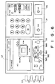
- Figure 6 is a view showing the initial state of the display on the control panel,
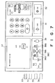
- Figure 7 is a view showing the state of the display on the control panel when setting the viscosity of the ink,
- Figure 8 is a view showing the state of the display on the control panel when setting the gap,
- Figure 9 is a view showing the state of the display on the control panel when setting the temperature,
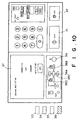
- Figure 10 is a view showing the state of the display on the control panel when setting the mode of the original,
- Figure 11 is a flow chart for illustrating general operation of the stencil printer of the embodiment,
- Figure 12 is a flow chart for illustrating printing operation of the stencil printer,
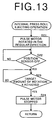
- Figure 13 is a flow chart for illustrating internal press roll ejecting operation of the stencil printer,
- Figure 14 is a time chart showing the internal press roll ejecting operation,
- Figure 15 is a flow chart for illustrating the internal press roll return operation,
- Figure 16 is a time chart showing the internal press roll return operation,
- Figure 17 is a flow chart for calculating the target amount of rotation of the pulse motor on the basis of the temperature of the ink,
- Figure 18 is a graph showing the relation between the temperature of the ink and the output of the third A/D converter,
- Figure 19 is a flow chart for calculating the target amount of rotation of the pulse motor on the basis of the temperature input through the control panel,
- Figure 20 is a flow chart for calculating the target amount of rotation of the pulse motor on the basis of the viscosity of the ink,
- Figure 21 is a graph showing the relation between the printing drum motor current and the output of the first A/D converter,
- Figure 22 is a flow chart for calculating the target amount of rotation of the pulse motor on the basis of the viscosity of the ink as detected on the basis of the amount of electric current supplied to the ink supply motor,
- Figure 23 is a flow chart for illustrating the ink supply interruption processing,
- Figure 24 is a time chart for the ink supply interruption processing,
- Figure 25 is a graph showing the relation between the ink supply motor current and the output of the second A/D converter,
- Figure 26 is a flow chart for calculating the target amount of rotation of the pulse motor on the basis of the viscosity of ink input through the control panel,
- Figure 27 is a flow chart for calculating the target amount of rotation of the pulse motor on the basis of the gap between the internal press roll and the doctor roll set by the internal press roll gap setting switch,
- Figure 28 is a flow chart for calculating the target amount of rotation of the pulse motor on the basis of the gap between the internal press roll and the doctor roll estimated on the basis of the cumulative number of times of printing, and
- Figure 29 is a flow chart for calculating the target amount of rotation of the pulse motor according to the original mode.
-
- In Figures 1 to 3, a stencil printer in accordance with an embodiment of the present invention comprises a
printing drum 1 which is substantially cylindrical and is supported for rotation about arotating shaft 2. Theprinting drum 1 has a peripheral wall which is ink-permeable and flexible. The peripheral wall of theprinting drum 1 is formed by rolling knitting or web of wire, or a perforated rectangular thin sheet into a cylinder having a central axis along therotating shaft 2. Therotating shaft 2 is supported for rotation on aframe 7 and is driven by a printing drum motor (not shown), whereby theprinting drum 1 is rotated about therotating shaft 2. In Figure 2, the peripheral wall of theprinting drum 1 is removed. - A
back press roll 3 is provided in a predetermined position below theprinting drum 1. Theback press roll 3 is provided with a drive shaft (not shown) parallel to therotating shaft 2 of theprinting drum 1. When printing is not effected, theback press roll 3 is held opposed to theprinting drum 1 with a gap intervening therebetween. When printing is effected, theprinting drum 1 and theback press roll 3 are rotated in opposite directions. That is, theprinting drum 1 is rotated in the clockwise direction as shown by arrow A and theback press roll 3 is rotated in the counterclockwise direction as shown by arrow B. - An
internal press roll 4 is provided in theprinting drum 1. Theinternal press roll 4 is formed of an elastic material such as rubber and pushes a part of the peripheral wall of theprinting drum 1 toward theback press roll 3 from inside the peripheral wall. Theinternal press roll 4 is supported for rotation at its opposite ends on a pair ofbase plates 6 which are supported for rotation about asupport shaft 5. Thesupport shaft 5 is supported on theframe 7 at a distance from therotating shaft 2 of theprinting drum 1 in parallel thereto. Theinternal press roll 4 is driven by the printing drum motor by way of therotating shaft 2 and a gear train (not shown). - Each of the
base plates 6 is provided with anopening 6a and aneccentric cam 8 which is rotated about therotating shaft 2 is in engagement with theopening 6a. Theeccentric cam 8 is formed integrally with asector gear 9 which is rotated about therotating shaft 2. Driving force of apulse motor 10 is transmitted to thesector gear 9 by way of amotor gear 11 and anidler gear 12, whereby thesector gear 9 and theeccentric cam 8 are rotated. Since theeccentric cam 8 is in engagement with theopening 6a of thebase plate 6 on each end of theinternal press roll 4 as described above, thebase plates 6 are rotated about thesupport shaft 5 as theeccentric cam 8 is rotated and theinternal press roll 4 is moved. - The position of the
internal press roll 4 where theinternal press roll 4 is held away from the peripheral wall of theprinting drum 1 and a gap is formed between the outer surface of the peripheral wall of theprinting drum 1 and theback press roll 3 as shown in Figure 1 will be referred to as "the initial position". An L-shaped light-shieldingplate 13 is mounted on thesector gear 9 and asensor 14 which is U-shaped in cross-section is disposed in a position where the light-shieldingplate 13 is inserted into thesensor 14 to turn on the output of thesensor 14 when theinternal press roll 4 is in the initial position. When theinternal press roll 4 is not in the initial position, the light-shieldingplate 13 is away from thesensor 14 and the output of thesensor 14 is turned off. - When the
pulse motor 10 is driven by a control means to be described later, thesector gear 9 is rotated by way of themotor gear 11 and theidler gear 12 and theeccentric cam 8 is rotated, whereby theinternal press roll 4 is moved from the initial position shown in Figure 1 to an operative position (printing position) shown in Figure 3. Then as shown in Figure 4, ink is supplied to theinternal press roll 4 through anink supply port 16 by an ink pump (not shown). Anink agitator rod 17 is disposed near theinternal press roll 4 to agitate the supplied ink. The supplied ink is agitated by theink agitator rod 17 and is uniformly coated on the surface of theinternal press roll 4 by adoctor roll 18. In this state, printing is effected. The distance of theinternal press roll 4 from therotating shaft 2 of theprinting drum 1 when theinternal press roll 4 is in the operative position, that is, the amount by which theinternal press roll 4 is moved from the initial position (this will be referred to as "the amount of ejection of theinternal press roll 4", hereinbelow), can be changed by changing the amount of rotation of theeccentric cam 8. The amount of rotation of theeccentric cam 8 can be changed by changing the number of pulses to be input into thepulse motor 10. In this particular embodiment, thepulse motor 10 is provided on each end of theinternal press roll 4, and accordingly, by separately controlling the numbers of pulses to be input into thepulse motors 10, the amount of ejection of theinternal press roll 4 can be differently controlled at the opposite ends of theinternal press roll 4. - Figure 5 shows the structure of the control means for controlling the amount of rotation of the
pulse motor 10. As shown in Figure 5, the control means 19 comprises a one-chip microcomputer 20, acontrol panel 30, an in-drum mechanism 40, adrive section 50 and a printingdrum drive section 60. - The one-
chip microcomputer 20 comprises aCPU 21, aROM 22 in which control program is stored, aRAM 23 for storing operating variables of theCPU 21 and the like, a first A/D converter 24 which digitizes the value of an electric current supplied to a printing drum motor for driving theprinting drum 1 in order to detect the viscosity of ink on the basis of the digitized value of the electric current supplied to the printing drum motor, a second A/D converter 25 which digitizes the value of an electric current supplied to an ink supply motor to be described later in order to detect the viscosity of ink on the basis of the digitized value of the electric current supplied to the ink supply motor, and a third A/D converter 26 which digitizes the value of an electric signal from a temperature sensor to be described later in order to detect the temperature inside theprinting drum 1 on the basis of the digitized value of the electric signal. - The
control panel 30 comprises astart key 31 for starting printing, astop key 32 for interrupting printing, an inkviscosity setting switch 33 for setting viscosity of ink, an internal press rollgap setting switch 34 for setting the width of the gap between theinternal press roll 4 and thedoctor roll 18, atemperature setting switch 35 for setting a temperature such as the temperature of environment in which the stencil printer is installed, and an originalmode setting switch 36 for setting the kind of the original to be used in printing as an original mode. - As shown in Figures 6 to 10, the
control panel 30 further comprises anLCD panel 37,selection keys 38A to 38D and averification key 39. Various frames are displayed by theLCD panel 37 and the operator can execute desired settings by operating theselection keys 38A to 38D and theverification key 39 under the guidance shown in the frames. - When the ink
viscosity setting switch 33 is depressed, an ink viscosity setting frame shown in Figure 7 appears on theLCD panel 37. One of "auto", "hard", "normal" and "soft" is selected by operating theselection keys 38A to 38D, and the selected ink viscosity is reversed. Then by depressing theverification key 39, the selected ink viscosity is verified and the initial frame shown in Figure 6 is displayed again. In Figures 7 to 10, the selected terms to be shown in reverse video are shown as surrounded by a rectangle. - When the internal press roll
gap setting switch 34 is depressed, an internal press roll gap setting frame shown in Figure 8 appears on theLCD panel 37. One of the values of the width of the gap between theinternal press roll 4 and thedoctor roll 18 is selected by operating theselection keys 38A to 38D, and the selected value of the width of the gap is reversed. Then by depressing theverification key 39, the selected value of the width of the gap is verified and the initial frame shown in Figure 6 is displayed again. - When the
temperature setting switch 35 is depressed, a temperature setting frame shown in Figure 9 appears on theLCD panel 37. One of "auto", "not lower than 30°C", "20°C - 30°C", "10°C - 20°C" and "lower than 10°C" is selected by operating theselection keys 38A to 38D, and the selected temperature is reversed. Then by depressing theverification key 39, the selected temperature is verified and the initial frame shown in Figure 6 is displayed again. Though the temperature is set here on the basis of the temperature of environment in which the stencil printer is installed, the operator may measure the temperature inside or around theprinting drum 1, and input a temperature on the basis of the measured temperature. - When the original
mode setting switch 36 is depressed, an original mode setting frame shown in Figure 10 appears on theLCD panel 37. One of "auto", "handwritten", "copy", "throwaway" and "with picture" is selected by operating theselection keys 38A to 38D, and the selected original mode is reversed. Then by depressing theverification key 39, the selected original mode is verified and the initial frame shown in Figure 6 is displayed again. - The in-
drum mechanism 40 comprises atemperature sensor 41 which detects the temperature of environment in which the stencil printer is installed, or the temperature inside or around theprinting drum 1, and inputs a detecting signal into the third A/D converter 26, an inkviscosity setting switch 42 for setting the viscosity of ink, an internal press rollgap setting switch 43, aposition sensor 14 which detects the initial position of theinternal press roll 4, anink sensor 44 which detects the size of an ink swirl on theinternal press roll 4, saidpulse motor 10, anink supply motor 45 which drives the ink pump (not shown) to supply ink to theinternal press roll 4, and acumulative number counter 46 which counts the cumulative number of times of printing. The inkviscosity setting switch 42 and the internal press rollgap setting switch 43 are provided on a unit for incorporating theprinting drum 1 in the stencil printer and are for setting the viscosity of ink and the width of the gap between theinternal press roll 4 and thedoctor roll 18 as those on thecontrol panel 30. - The
drive section 50 comprises a pulsemotor drive circuit 51 for driving thepulse motor 10, an ink supplymotor drive circuit 52 for driving theink supply motor 45, and an ink supply motorcurrent detecting circuit 53 which detects the electric current supplied to theink supply motor 45 and inputs a detecting signal representing the electric current supplied to theink supply motor 45 into the second A/D converter 25. - The printing
drum drive section 60 comprises aprinting drum motor 61 which drives theprinting drum 1, a printing drummotor drive circuit 62 for driving theprinting drum motor 61, and a printing drum motor current detectingcircuit 63 which detects the electric current supplied to theprinting drum motor 61 and inputs a detecting signal representing the electric current supplied to theprinting drum motor 61 into the first A/D converter 24. - Operation of the stencil printer of this embodiment will be described, hereinbelow. Figure 11 is a flow chart for illustrating general operation of the stencil printer of this embodiment. When the
start key 31 is depressed, feeding of printing paper is started, and then a printing operation and a paper discharge operation are effected. (steps S1 to S4) Then the cumulative number of times of printing is counted (step S5) Steps S2 to S5 are repeated until thestop key 32 is depressed. (step S6) When thestop key 32 is depressed, the system waits for the start key 31 to be depressed. (step S1) - As shown in Figure 12, in the printing operation, the target amount of rotation X by which the
pulse motor 10 is to be rotated is first calculated. (step S11) Then thepulse motor 10 is driven on the basis of the calculated target amount of rotation X and theinternal press roll 4 is ejected (step S12) and printing is done with the amount of ejection of theinternal press roll 4 corresponding to the calculated amount of rotation X of the pulse motor 10 (step S13). After printing is finished, theinternal press roll 4 is returned to the initial position. (step S14) - As shown in Figure 13, in the internal press roll ejecting operation, the
pulse motor 10 is rotated in the regular direction, i.e., in the direction in which theinternal press roll 4 is pushed toward theback press roll 3 to press the peripheral wall of theprinting drum 1 against theback press roll 3. (step S21) Thepulse motor 10 is kept driven until theposition sensor 14 is turned off (thelight shielding plate 13 is moved from the position where it opposed to the position sensor 14) and the rotation of thepulse motor 10 reaches the target amount of rotation X calculated in step S11. (steps S23 to S24) Figure 14 is a time chart showing this internal press roll ejecting operation. - Figure 15 is a flow chart for illustrating the internal press roll return operation. As shown in Figure 15, in the internal press roll return operation, the
pulse motor 10 is reversed to move theinternal press roll 4 away from theback press roll 3 until theposition sensor 14 is turned on, and then thepulse motor 10 is stopped. (steps S31 to S33) Figure 16 is a time chart showing this internal press roll return operation. - Calculation of the target amount of rotation X of the
pulse motor 10 will be described, hereinbelow. Figure 17 is a flow chart for calculating the target amount of rotation X of thepulse motor 10 on the basis of the temperature of the ink. That is, when the temperature inside or around theprinting drum 1 or the temperature of environment in which the stencil printer is installed, and the temperature of ink is low, the viscosity of ink becomes high and the printing density for a given printing pressure becomes low. To the contrast, when the temperature of ink is high, the viscosity of ink becomes low and the printing density for a given printing pressure becomes high. Accordingly, in this particular embodiment, the printing pressure is changed by changing the amount of ejection of theinternal press roll 4 according to the temperature inside or around theprinting drum 1 or the temperature of environment in which the stencil printer is installed detected by thetemperature sensor 41 so that the printing density is kept constant irrespective of the temperature of the ink. - As shown in Figure 17, the detecting signal of the
temperature sensor 41 is input into theCPU 21 through the third A/D converter 26. (step S41) As shown in Figure 18, the output of the third A/D converter 26 is proportional to the temperature of the ink. When the temperature of the ink is not lower than 30°C (output of the third A/D converter 26 is not smaller than 60), the target amount of rotation X is set to 90 steps. (steps S42 and S43) When the temperature of the ink is not lower than 25°C and lower than 30°C (output of the third A/D converter 26 is not smaller than 50 and smaller than 60), the target amount of rotation X is set to 95 steps. (steps S42, S44 and S45) When the temperature of the ink is not lower than 20°C and lower than 25°C (output of the third A/D converter 26 is not smaller than 40 and smaller than 50), the target amount of rotation X is set to 100 steps. (steps S42, S44, S46 and S47) When the temperature of the ink is not lower than 15°C and lower than 20°C (output of the third A/D converter 26 is not smaller than 30 and smaller than 40), the target amount of rotation X is set to 105 steps. (steps S42, S44, S46, S48 and S49) When the temperature of the ink is lower than 15°C (step S48: NO), the target amount of rotation X is set to 110 steps (step S50). - Figure 19 is a flow chart for calculating the target amount of rotation X of the
pulse motor 10 on the basis of the temperature input through thecontrol panel 30. As shown in Figure 19, when the temperature set in the temperature setting frame shown in Figure 9 is not lower than 30°C, the target amount of rotation X is set to 90 steps. (steps S51 and S52) When the temperature set in the temperature setting frame is not lower than 20°C and lower than 30°C, the target amount of rotation X is set to 95 steps. (steps S51, S53 and S54) When the temperature set in the temperature setting frame is not lower than 10°C and lower than 20°C, the target amount of rotation X is set to 100 steps. (steps S51, S53, S55 and S56) When the temperature set in the temperature setting frame is lower than 10°C (step S55: NO), the target amount of rotation X is set to 105 steps (step S57). - By increasing the target amount of rotation X of the
pulse motor 10 as the temperature of the ink lowers, the amount of ejection of theinternal press roll 4 is increased and the printing pressure increases. Accordingly, the printing pressure is changed according to the viscosity of the ink, which depends upon the temperature of the ink, so that the printing density is kept constant irrespective of the temperature of the ink. - Though, in this embodiment, the temperature of the ink is detected through the temperature inside or around the
printing drum 1 or the temperature of environment in which the stencil printer is installed, the temperature of the ink may be directly detected. - Figure 20 is a flow chart for calculating the target amount of rotation X of the
pulse motor 10 on the basis of the viscosity of the ink. That is, as the viscosity of ink becomes higher (the ink is harder), it becomes more difficult to eject the ink through theprinting drum 1 and the printing density for a given printing pressure becomes lower. To the contrast, as the viscosity of ink becomes lower, it becomes easier to eject the ink through theprinting drum 1 and the printing density for a given printing pressure becomes higher. Accordingly, the printing pressure is changed by changing the amount of ejection of theinternal press roll 4 according to the viscosity of the ink so that the printing density is kept constant irrespective of the viscosity of the ink. The viscosity of the ink is detected here by way of the amount of electric current supplied to theprinting drum motor 61. That is, theink agitator rod 17 agitates the ink swirl under the driving force of theprinting drum motor 61 and accordingly, the driving force required to drive theink agitator rod 17 changes with the viscosity of the ink. Accordingly, the viscosity of the ink can be estimated on the basis of the amount of electric current supplied to theprinting drum motor 61 when agitating the ink, which may be considered to be in proportional to the torque on theink agitator rod 17. - As shown in Figure 20, the detecting signal of the printing drum motor current detecting
circuit 63 is input into theCPU 21 through the first A/D converter 24. (step S61) As shown in Figure 21, the output of the first A/D converter 24 is proportional to the amount of electric current supplied to theprinting drum motor 61. When the output of the first A/D converter 24 is not smaller than 120 (the amount of electric current supplied to theprinting drum motor 61 is not smaller than 6A), the target amount of rotation X is set to 105 steps. (steps S62 and S63) When the output of the first A/D converter 24 is not smaller than 80 and smaller than 120 (the amount of electric current supplied to theprinting drum motor 61 is not smaller than 4A and smaller than 6A), the target amount of rotation X is set to 100 steps. (steps S62, S64 and S65) When the output of the first A/D converter 24 is smaller than 80 (the amount of electric current supplied to theprinting drum motor 61 is smaller than 4A) (step S64: NO), the target amount of rotation X is set to 95 steps (step S66). - Figure 22 is a flow chart for calculating the target amount of rotation X of the
pulse motor 10 on the basis of the viscosity of the ink as detected on the basis of the amount of electric current supplied to theink supply motor 45. In Figure 22, a variable Y which has been stored in an ink supply interruption processing is input into theCPU 21. (step S71) Figure 23 is a flow chart for illustrating the ink supply interruption processing. As shown in Figure 23, in the ink supply interruption processing, it is determined whether theink supply motor 45 is rotating. (step S81) When it is determined that theink supply motor 45 is rotating, the detecting signal of the ink supply motorcurrent detecting circuit 53 is input into theCPU 21 through the second A/D converter 25 and the value of the output of the second A/D converter 25 is stored in theRAM 23 as the variable Y. (step S82) As shown in Figure 25, the output of the second A/D converter 25 is proportional to the ink supply motor current. Further, it is determined whether theink sensor 44 is off, that is, whether theink sensor 44 has detected ink. (step S83) When it is determined that theink sensor 44 is off, theink supply motor 45 is turned off (step S84) and the processing returns. When it is determined that theink sensor 44 is not off, the processing directly returns. When it is determined in step S81 that theink supply motor 45 is not rotating, it is determined in step S85 whether the output of theink sensor 44 is on (the output of theink sensor 44 is turned on when theink sensor 44 does not detect ink). When it is determined that the output of theink sensor 44 is on, the processing returns after theink supply motor 45 started (step S86), and otherwise the processing directly returns. Figure 24 is a time chart for the ink supply interruption processing. - Again in Figure 22, when the value of the variable Y is not smaller than 100 (the ink supply motor current is not smaller than 1A), the target amount of rotation X is set to 105 steps. (steps S72 and S73) When the value of the variable Y is not smaller than 50 and smaller than 100 (the ink supply motor current is not smaller than 0.5A and smaller than 1A), the target amount of rotation X is set to 100 steps. (steps S72, S74 and S75) When the value of the variable Y is smaller than 50 (the ink supply motor current is smaller than 0.5A) (step S74: NO), the target amount of rotation X is set to 95 steps (step S76).
- Figure 26 is a flow chart for calculating the target amount of rotation X of the
pulse motor 10 on the basis of the viscosity of ink input through thecontrol panel 30. As shown in Figure 26, when the viscosity of ink set in the ink viscosity setting frame shown in Figure 7 is "hard", the target amount of rotation X is set to 105 steps. (steps S91 and S92) When the viscosity of ink set in the ink viscosity setting frame is "soft", the target amount of rotation X is set to 95 steps. (steps S91, S93 and S94) When the viscosity of ink set in the ink viscosity setting frame is "normal", the target amount of rotation X is set to 100 steps. (steps S91, S93 and S95) - By increasing the target amount of rotation X of the
pulse motor 10 as the viscosity of ink increases, the amount of ejection of theinternal press roll 4 is increased and the printing pressure increases. Accordingly, the printing pressure is changed according to the viscosity of ink so that the printing density is kept constant irrespective of the viscosity of ink. - Figure 27 is a flow chart for calculating the target amount of rotation X of the
pulse motor 10 on the basis of the gap between theinternal press roll 4 and thedoctor roll 18 set by the internal press rollgap setting switch 43. Since theinternal press roll 4 is of an elastic material such as rubber, the surface of theinternal press roll 4 wears and the gap between theinternal press roll 4 and thedoctor roll 18 is increased by repeated printing operations. When the gap between theinternal press roll 4 and thedoctor roll 18 is widened, an excessive amount of ink is deposited on theinternal press roll 4 and the printing density becomes higher. In the processing shown in Figure 7, the target amount of rotation X of thepulse motor 10 is calculated so that a desired printing density can be obtained irrespective of the amount of wear of theinternal press roll 4. - As shown in Figure 27, when the internal press roll
gap setting switch 43 is set to "narrow gap", which represents that the wear of theinternal press roll 4 is little and the gap between theinternal press roll 4 and thedoctor roll 18 is narrow, the target amount of rotation X is set to 105 steps. (steps S101 and S102) When the internal press rollgap setting switch 43 is set to "wide gap", the target amount of rotation X is set to 95 steps. (steps S101, S103 and S104) When the internal press rollgap setting switch 43 is set to "normal gap", the target amount of rotation X is set to 100 steps. (steps S101, S103 and S105) The target amount of rotation X may be calculated on the basis of the gap set in the internal press roll gap setting frame shown in Figure 8. - Figure 28 is a flow chart for calculating the target amount of rotation X of the
pulse motor 10 on the basis of the gap between theinternal press roll 4 and thedoctor roll 18 estimated on the basis of the cumulative number of times of printing counted by thecumulative number counter 46. As shown in Figure 28, when the count of thecumulative number counter 46 is not smaller than 200,000, which represents that the wear of theinternal press roll 4 is large and the gap between theinternal press roll 4 and thedoctor roll 18 is wide, the target amount of rotation X is set to 90 steps. (steps S111 and S112) When the count of thecumulative number counter 46 is not smaller than 100,000 and smaller than 200,000, which represents that the wear of theinternal press roll 4 is relatively large and the gap between theinternal press roll 4 and thedoctor roll 18 is relatively wide, the target amount of rotation X is set to 95 steps. (steps S111, S113 and S114) When the count of thecumulative number counter 46 is smaller than 100,000, which represents that the wear of theinternal press roll 4 is little and the gap between theinternal press roll 4 and thedoctor roll 18 is narrow, the target amount of rotation X is set to 100 steps. (steps S111, S113 and S115) - By thus reducing the target amount of rotation X of the
pulse motor 10 as the gap between theinternal press roll 4 and thedoctor roll 18 is widened, the amount of ejection of theinternal press roll 4 is reduced and the printing pressure is lowered. As a result, the printing density is kept constant irrespective of the amount of wear of theinternal press roll 4 or the width of the gap between theinternal press roll 4 and thedoctor roll 18. - Figure 29 is a flow chart for calculating the target amount of rotation X of the
pulse motor 10 according to the original mode. As the original for printing, various types of originals such as a handwritten original, a copied original, an original for throwaway and the like are used, and a proper printing density differs according to the type of the original. In the processing shown in Figure 29, the target amount of rotation X of thepulse motor 10 is calculated so that a proper printing density id obtained irrespective of the type of the original or the original mode. - As shown in Figure 29, when the original mode set in the original mode setting frame shown in Figure 10 is "handwritten", the target amount of rotation X is set to 105 steps for the purpose of increasing the printing density. (steps S121 and S122) When the original mode set in the original mode setting frame shown in Figure 10 is "copy", the target amount of rotation X is set to 90 steps for the purpose of preventing saturation in detail. (steps S123 and S124) When the original mode set in the original mode setting frame shown in Figure 10 is "throwaway", the target amount of rotation X is set to 110 steps for the purpose of preventing skip in a solid part (steps S125 and S126) When the original mode set in the original mode setting frame shown in Figure 10 is "with picture", the target amount of rotation X is set to 95 steps for the purpose of properly expressing the gradation. (steps S127 and S128) Otherwise, the target amount of rotation X is set to 100 steps. (step S129)
- By setting the target amount of rotation X, a proper printing density can be obtained according to type of the original.
- The type of the original may be automatically detected in the manner disclosed, for instance, in Japanese Unexamined Patent Publication No. 7(1995)-322061 and the target amount of rotation X may be calculated on the basis of the type of the original.
- Further it is possible to make it feasible to select an economy mode in the original mode setting frame shown in Figure 10 and to reduce the target amount of rotation X in order to reduce consumption of ink when the economy mode is selected.
- Though, in the embodiment described above, the amount of rotation of the
pulse motor 10, that is, the amount of ejection of the internal press roll, is changed according to the viscosity of ink, the temperature of ink, the gap between theinternal press roll 4 and thedoctor roll 18 or the original mode, the amount of rotation of thepulse motor 10 may be changed according to the printing speed. That is, the printing paper is nipped between theinternal press roll 4 and theback press roll 3 and as the printing speed increases, the time for which the printing paper is nipped between theinternal press roll 4 and theback press roll 3 is shortened and the amount of ink transferred to the printing paper is reduced. That is, the printing density fluctuates with the printing speed. By changing the amount of ejection of theinternal press roll 4 according to the printing speed, the printing density can be stabilized irrespective of the printing speed. - Specifically, when the radius of the
printing drum 1 is represented by R, the printing speed is changed in two speeds, one corresponding to 80rpm of theprinting drum 1 and the other corresponding to 120rpm of theprinting drum 1, and the nipping length of the printing paper (by which the printing paper is nipped between theinternal press roll 4 and theback press roll 3 in the direction of conveyance of the printing paper) is 10mm, the conveying speed of the printing paper is 2.667 πRmm/sec in the case of the printing speed of 80rpm and 4.000 πRmm/sec in the case of the printing speed of 120rpm. In this case, the nipping time is 10mm/2.667πRmm/sec=3.75πRsec and 10mm/4.000πRmm/sec=2.50πRsec. In order to substantially equalize the nipping time, it is necessary to reduce the nipping length when the printing speed is 80rpm as compared with when the printing speed is 120rpm. The nipping length can be reduced by reducing the amount of ejection of theinternal press roll 4 or the amount of rotation of thepulse motor 10. That is, by reducing the amount of ejection of theinternal press roll 4 so that the nipping length becomes 6.667mm when the printing speed is 80rpm, the nipping time can be substantially equalized to that when the printing speed is 120rpm. That is, 6.667mm/2.667πRmm/sec=2.50πRsec. By thus changing the amount of ejection of theinternal press roll 4 according to the printing speed, the amount of ink transferred to the printing paper can be substantially constant and the printing density can be substantially constant irrespective of the printing speed. - Though, in the embodiment described above, the amount of rotation of the
pulse motor 10, that is, the amount of ejection of the internal press roll, is changed according to the viscosity of ink, the temperature of ink, the gap between theinternal press roll 4 and thedoctor roll 18 or the original mode, the amount of rotation of thepulse motor 10 may be changed to user liking. For example, by setting the amount of ejection of the internal press roll through thecontrol panel 30 to the user liking, the printed image can be in a density to the user liking. - Further, since the amount of ejection of the
internal press roll 4 can be differently set at the opposite ends of theinternal press roll 4 in the particular embodiment described above, the printing pressure can be easily made uniform even if dimensional accuracy and assembling accuracy of the components of the stencil printer are not so high. Further printing can be done in different densities in the direction of width of the printing paper. - Further, though the amount of ejection of the
internal press roll 4 can be differently set at the opposite ends of theinternal press roll 4 in the particular embodiment described above, the system may be arranged so that the amount of ejection of theinternal press roll 4 cannot be differently set at the opposite ends of theinternal press roll 4. - Further, though, in the embodiment described above, the amount of ejection of the
internal press roll 4 is changed by use of thepulse motor 10 and theeccentric cam 8, other various mechanism may be used. - In addition, all of the contents of Japanese Patent Application No. 11(1999)-218839 are incorporated into this specification by reference.
Claims (19)
- A stencil printer comprising a printing drum which has an ink-permeable peripheral wall and is rotated about a predetermined axis of rotation with a stencil master wound around the peripheral wall, a back press roll which associates with the printing drum to nip and convey a printing paper, and an internal press roll which is provided in the printing drum to be movable back and forth toward and away from the back press roll and pushes the peripheral wall of the printing drum toward the back press roll, wherein the improvement comprisesan internal press roll drive means which moves back and forth the internal press roll between a first position where the internal press roll is held away from the back press roll and a second position at a distance from the first position toward the back press roll and is able to freely change the distance between the axis of rotation of the printing drum and the second position.
- A stencil printer as defined in Claim 1 in which the internal press roll drive means is provided with a means for moving opposite ends of the internal press roll independently of each other.
- A stencil printer as defined in Claim 1 in which the stencil printer further comprises a printing speed setting means for setting the printing speed and the internal press roll drive means changes the distance between the axis of rotation of the printing drum and the second position according to the printing speed set by the printing speed setting means.
- A stencil printer as defined in Claim 1 in which the stencil printer further comprises an ink temperature detecting means which detects the temperature of the ink and the internal press roll drive means changes the distance between the axis of rotation of the printing drum and the second position according to the temperature of the ink detected by the ink temperature detecting means.
- A stencil printer as defined in Claim 4 in which the ink temperature detecting means detects the temperature of the ink through the ambient temperature of the printing drum, the temperature inside the printing drum or the ambient temperature of the stencil printer.
- A stencil printer as defined in Claim 1 in which the stencil printer further comprises an ink temperature input means for manually inputting a temperature of the ink, and the internal press roll drive means changes the distance between the axis of rotation of the printing drum and the second position according to the temperature of the ink input through the ink temperature input means.
- A stencil printer as defined in Claim 6 in which the temperature of the ink is represented by the ambient temperature of the printing drum, the temperature inside the printing drum or the ambient temperature of the stencil printer.
- A stencil printer as defined in Claim 1 in which the stencil printer further comprises an ink viscosity detecting means which detects the viscosity of the ink and the internal press roll drive means changes the distance between the axis of rotation of the printing drum and the second position according to the viscosity of the ink detected by the ink viscosity detecting means.
- A stencil printer as defined in Claim 8 in which the ink viscosity detecting means detects the viscosity of the ink through the electric current supplied to the electric motor for driving the printing drum or to the electric motor for supplying the ink to the printing drum.
- A stencil printer as defined in Claim 1 in which the stencil printer further comprises an ink viscosity input means for manually inputting a viscosity of the ink, and the internal press roll drive means changes the distance between the axis of rotation of the printing drum and the second position according to the viscosity of the ink input through the ink viscosity input means.
- A stencil printer as defined in Claim 10 in which the viscosity of the ink is represented by the electric current supplied to the electric motor for driving the printing drum or to the electric motor for supplying the ink to the printing drum.
- A stencil printer as defined in Claim 1 in which the stencil printer further comprises a wear detecting means which detects the amount of wear of the internal press roll and the internal press roll drive means changes the distance between the axis of rotation of the printing drum and the second position according to the amount of wear of the internal press roll detected by the wear detecting means.
- A stencil printer as defined in Claim 12 in which the wear detecting means detects the amount of wear of the internal press roll on the basis of the cumulative number of times of printing.
- A stencil printer as defined in Claim 1 in which the stencil printer further comprises a wear input means for manually inputting the amount of wear of the internal press roll, and the internal press roll drive means changes the distance between the axis of rotation of the printing drum and the second position according to the amount of wear of the internal press roll input through the wear input means.
- A stencil printer as defined in Claim 14 in which the amount of wear is estimated on the basis of the cumulative number of times of printing.
- A stencil printer as defined in Claim 1 in which the stencil printer further comprises an original type setting means which sets the type of the original, and the internal press roll drive means changes the distance between the distance between the axis of rotation of the printing drum and the second position according to the type of the original set by the original type setting means.
- A stencil printer as defined in Claim 1 in which the stencil printer further comprises an original type input means for manually inputting the type of the original, and the internal press roll drive means changes the distance between the axis of rotation of the printing drum and the second position according to the type of the original input through the original type input means.
- A stencil printer as defined in Claim 1 in which the internal press roll drive means comprisesa support member which supports opposite ends of the internal press roll and is rotatable about a predetermined axis of rotation,a cam member which is in abutment against the support member and is rotated to move up and down the support member, anda rotation control means which controls the amount of rotation of the cam member.
- A stencil printer as defined in Claim 18 in which the rotation control means is a pulse motor.
Applications Claiming Priority (2)
| Application Number | Priority Date | Filing Date | Title |
|---|---|---|---|
| JP21883999 | 1999-08-02 | ||
| JP21883999A JP3798193B2 (en) | 1999-08-02 | 1999-08-02 | Stencil printing machine |
Publications (2)
| Publication Number | Publication Date |
|---|---|
| EP1074396A1 true EP1074396A1 (en) | 2001-02-07 |
| EP1074396B1 EP1074396B1 (en) | 2004-02-11 |
Family
ID=16726155
Family Applications (1)
| Application Number | Title | Priority Date | Filing Date |
|---|---|---|---|
| EP00116409A Expired - Lifetime EP1074396B1 (en) | 1999-08-02 | 2000-07-28 | Stencil printer |
Country Status (4)
| Country | Link |
|---|---|
| US (1) | US6508168B1 (en) |
| EP (1) | EP1074396B1 (en) |
| JP (1) | JP3798193B2 (en) |
| DE (1) | DE60008173T2 (en) |
Cited By (1)
| Publication number | Priority date | Publication date | Assignee | Title |
|---|---|---|---|---|
| DE20321898U1 (en) | 2002-07-22 | 2012-05-30 | Dieffenbacher GmbH Maschinen- und Anlagenbau | Plant for the production of fiber-reinforced molded parts |
Families Citing this family (3)
| Publication number | Priority date | Publication date | Assignee | Title |
|---|---|---|---|---|
| EP1946925A3 (en) * | 2007-01-22 | 2010-12-22 | Komori Corporation | Ink transfer member position adjusting method and apparatus of rotary stencil printing press |
| US8230889B2 (en) * | 2008-07-15 | 2012-07-31 | Anthony Pratt | Fluid transfer apparatus |
| JP6121264B2 (en) * | 2013-06-26 | 2017-04-26 | 理想科学工業株式会社 | Image forming apparatus |
Citations (4)
| Publication number | Priority date | Publication date | Assignee | Title |
|---|---|---|---|---|
| EP0046951A1 (en) * | 1980-08-28 | 1982-03-10 | Mathias Mitter | Application mechanism with a cylindrical stencil or the like and a spreader roll lying therein |
| GB2241672A (en) * | 1990-03-06 | 1991-09-11 | Riso Kagaku Corp | Mimeographic printing machine |
| DE4128700A1 (en) * | 1991-08-29 | 1993-03-04 | Tts Textilmaschinen Technologi | Carpet rotary printer - has height adjustment for paste application roller independently of stencil |
| EP0715962A1 (en) * | 1994-12-08 | 1996-06-12 | Riso Kagaku Corporation | Rotary stencil printer having gear train with breaking device for synchronizing the movement of the inner press roller with the rotation of the printing boom |
Family Cites Families (8)
| Publication number | Priority date | Publication date | Assignee | Title |
|---|---|---|---|---|
| JP2876210B2 (en) | 1988-02-09 | 1999-03-31 | 理想科学工業株式会社 | Rotary stencil printing machine |
| AT392745B (en) * | 1989-08-16 | 1991-05-27 | Zimmer Johannes | DEVICE AND METHOD FOR SAMPLE AND / OR FULL AREA APPLICATION PROCESSES ON SHORT AND ANY LONG TRACKS |
| JP3342163B2 (en) * | 1993-11-12 | 2002-11-05 | 理想科学工業株式会社 | Stencil printing press with ink leakage prevention structure |
| JPH07322061A (en) | 1994-05-30 | 1995-12-08 | Riso Kagaku Corp | Method and device for distinguishing characters and photographs |
| JP3292427B2 (en) * | 1994-11-25 | 2002-06-17 | 理想科学工業株式会社 | Stencil stencil starter for rotary stencil printing press |
| JP3379614B2 (en) * | 1994-12-08 | 2003-02-24 | 理想科学工業株式会社 | Rotary stencil printing press having a press roller synchronous system capable of controlling plate cylinder extrusion and method of controlling cylinder cylinder extrusion |
| JP4312284B2 (en) * | 1998-08-21 | 2009-08-12 | 東北リコー株式会社 | Stencil printing machine |
| JP2000108483A (en) * | 1998-10-01 | 2000-04-18 | Riso Kagaku Corp | Stencil printing machine |
-
1999
- 1999-08-02 JP JP21883999A patent/JP3798193B2/en not_active Expired - Fee Related
-
2000
- 2000-07-28 DE DE2000608173 patent/DE60008173T2/en not_active Expired - Fee Related
- 2000-07-28 EP EP00116409A patent/EP1074396B1/en not_active Expired - Lifetime
- 2000-08-01 US US09/630,547 patent/US6508168B1/en not_active Expired - Fee Related
Patent Citations (6)
| Publication number | Priority date | Publication date | Assignee | Title |
|---|---|---|---|---|
| EP0046951A1 (en) * | 1980-08-28 | 1982-03-10 | Mathias Mitter | Application mechanism with a cylindrical stencil or the like and a spreader roll lying therein |
| GB2241672A (en) * | 1990-03-06 | 1991-09-11 | Riso Kagaku Corp | Mimeographic printing machine |
| JPH03254984A (en) * | 1990-03-06 | 1991-11-13 | Riso Kagaku Corp | Stencil printing press |
| DE4128700A1 (en) * | 1991-08-29 | 1993-03-04 | Tts Textilmaschinen Technologi | Carpet rotary printer - has height adjustment for paste application roller independently of stencil |
| EP0715962A1 (en) * | 1994-12-08 | 1996-06-12 | Riso Kagaku Corporation | Rotary stencil printer having gear train with breaking device for synchronizing the movement of the inner press roller with the rotation of the printing boom |
| JPH08207416A (en) * | 1994-12-08 | 1996-08-13 | Riso Kagaku Corp | Rotary cylinder type stencil printing machine having a middle press roller synchronizing system capable of controlling plate cylinder extrusion and plate cylinder extrusion control method |
Cited By (1)
| Publication number | Priority date | Publication date | Assignee | Title |
|---|---|---|---|---|
| DE20321898U1 (en) | 2002-07-22 | 2012-05-30 | Dieffenbacher GmbH Maschinen- und Anlagenbau | Plant for the production of fiber-reinforced molded parts |
Also Published As
| Publication number | Publication date |
|---|---|
| DE60008173D1 (en) | 2004-03-18 |
| US6508168B1 (en) | 2003-01-21 |
| JP3798193B2 (en) | 2006-07-19 |
| DE60008173T2 (en) | 2005-01-13 |
| JP2001039000A (en) | 2001-02-13 |
| EP1074396B1 (en) | 2004-02-11 |
Similar Documents
| Publication | Publication Date | Title |
|---|---|---|
| JP2950414B2 (en) | Paper pressure adjustment device for printer | |
| US20070166061A1 (en) | Image forming apparatus and image forming method | |
| US20230244170A1 (en) | Image forming apparatus and control method thereof | |
| EP1074396B1 (en) | Stencil printer | |
| JPH0596710A (en) | Ink supply controller for stencil printer | |
| US20060144263A1 (en) | Stencil printer with a duplex printing capability | |
| JP4961905B2 (en) | Image forming apparatus | |
| JP2009107188A (en) | Device and method for setting zero point of ink supply arrangement of printing machine, and device and method for adjusting ink supply arrangement | |
| JPH0415741B2 (en) | ||
| US7325492B2 (en) | Stencil printer | |
| JPH08113408A (en) | Paper discharging device | |
| KR100465323B1 (en) | Duplex printing apparatus indicating recycled paper loaded | |
| JP3723068B2 (en) | Plate making printing apparatus and plate making printing method | |
| JP2000347528A (en) | Fixing device | |
| US20260093201A1 (en) | Image forming apparatus, and abnormality determination method | |
| JP2001246732A (en) | Method and apparatus for printing | |
| JP4921030B2 (en) | Stencil printing machine | |
| JP2000075717A (en) | Fixing device web device | |
| JP2019147257A (en) | Image formation apparatus | |
| JP2023163652A (en) | Image forming device | |
| JP4849425B2 (en) | Ink supply device | |
| JP2005148414A (en) | Image forming apparatus | |
| KR20080015323A (en) | Image forming apparatus and developer stirrer control method | |
| JPH1138823A (en) | Fixing device | |
| JP2020069729A (en) | Printing system |
Legal Events
| Date | Code | Title | Description |
|---|---|---|---|
| PUAI | Public reference made under article 153(3) epc to a published international application that has entered the european phase |
Free format text: ORIGINAL CODE: 0009012 |
|
| 17P | Request for examination filed |
Effective date: 20000728 |
|
| AK | Designated contracting states |
Kind code of ref document: A1 Designated state(s): DE FR GB |
|
| AX | Request for extension of the european patent |
Free format text: AL;LT;LV;MK;RO;SI |
|
| AKX | Designation fees paid |
Free format text: DE FR GB |
|
| GRAP | Despatch of communication of intention to grant a patent |
Free format text: ORIGINAL CODE: EPIDOSNIGR1 |
|
| GRAS | Grant fee paid |
Free format text: ORIGINAL CODE: EPIDOSNIGR3 |
|
| GRAA | (expected) grant |
Free format text: ORIGINAL CODE: 0009210 |
|
| AK | Designated contracting states |
Kind code of ref document: B1 Designated state(s): DE FR GB |
|
| REG | Reference to a national code |
Ref country code: GB Ref legal event code: FG4D |
|
| REF | Corresponds to: |
Ref document number: 60008173 Country of ref document: DE Date of ref document: 20040318 Kind code of ref document: P |
|
| ET | Fr: translation filed | ||
| PLBE | No opposition filed within time limit |
Free format text: ORIGINAL CODE: 0009261 |
|
| STAA | Information on the status of an ep patent application or granted ep patent |
Free format text: STATUS: NO OPPOSITION FILED WITHIN TIME LIMIT |
|
| 26N | No opposition filed |
Effective date: 20041112 |
|
| PGFP | Annual fee paid to national office [announced via postgrant information from national office to epo] |
Ref country code: DE Payment date: 20080807 Year of fee payment: 9 |
|
| PGFP | Annual fee paid to national office [announced via postgrant information from national office to epo] |
Ref country code: FR Payment date: 20080718 Year of fee payment: 9 |
|
| PGFP | Annual fee paid to national office [announced via postgrant information from national office to epo] |
Ref country code: GB Payment date: 20080806 Year of fee payment: 9 |
|
| GBPC | Gb: european patent ceased through non-payment of renewal fee |
Effective date: 20090728 |
|
| REG | Reference to a national code |
Ref country code: FR Ref legal event code: ST Effective date: 20100331 |
|
| PG25 | Lapsed in a contracting state [announced via postgrant information from national office to epo] |
Ref country code: FR Free format text: LAPSE BECAUSE OF NON-PAYMENT OF DUE FEES Effective date: 20090731 |
|
| PG25 | Lapsed in a contracting state [announced via postgrant information from national office to epo] |
Ref country code: GB Free format text: LAPSE BECAUSE OF NON-PAYMENT OF DUE FEES Effective date: 20090728 |
|
| PG25 | Lapsed in a contracting state [announced via postgrant information from national office to epo] |
Ref country code: DE Free format text: LAPSE BECAUSE OF NON-PAYMENT OF DUE FEES Effective date: 20100202 |