EP1074379A2 - Method and apparatus for manufacturing pneumatic tires - Google Patents
Method and apparatus for manufacturing pneumatic tires Download PDFInfo
- Publication number
- EP1074379A2 EP1074379A2 EP00306662A EP00306662A EP1074379A2 EP 1074379 A2 EP1074379 A2 EP 1074379A2 EP 00306662 A EP00306662 A EP 00306662A EP 00306662 A EP00306662 A EP 00306662A EP 1074379 A2 EP1074379 A2 EP 1074379A2
- Authority
- EP
- European Patent Office
- Prior art keywords
- carved
- groove
- tire
- mold
- tread
- Prior art date
- Legal status (The legal status is an assumption and is not a legal conclusion. Google has not performed a legal analysis and makes no representation as to the accuracy of the status listed.)
- Granted
Links
Images





Classifications
-
- B—PERFORMING OPERATIONS; TRANSPORTING
- B29—WORKING OF PLASTICS; WORKING OF SUBSTANCES IN A PLASTIC STATE IN GENERAL
- B29D—PRODUCING PARTICULAR ARTICLES FROM PLASTICS OR FROM SUBSTANCES IN A PLASTIC STATE
- B29D30/00—Producing pneumatic or solid tyres or parts thereof
- B29D30/0005—Pretreatment of tyres or parts thereof, e.g. preheating, irradiation, precuring
-
- B—PERFORMING OPERATIONS; TRANSPORTING
- B29—WORKING OF PLASTICS; WORKING OF SUBSTANCES IN A PLASTIC STATE IN GENERAL
- B29D—PRODUCING PARTICULAR ARTICLES FROM PLASTICS OR FROM SUBSTANCES IN A PLASTIC STATE
- B29D30/00—Producing pneumatic or solid tyres or parts thereof
- B29D30/06—Pneumatic tyres or parts thereof (e.g. produced by casting, moulding, compression moulding, injection moulding, centrifugal casting)
- B29D30/0601—Vulcanising tyres; Vulcanising presses for tyres
- B29D30/0606—Vulcanising moulds not integral with vulcanising presses
-
- B—PERFORMING OPERATIONS; TRANSPORTING
- B29—WORKING OF PLASTICS; WORKING OF SUBSTANCES IN A PLASTIC STATE IN GENERAL
- B29D—PRODUCING PARTICULAR ARTICLES FROM PLASTICS OR FROM SUBSTANCES IN A PLASTIC STATE
- B29D30/00—Producing pneumatic or solid tyres or parts thereof
- B29D30/06—Pneumatic tyres or parts thereof (e.g. produced by casting, moulding, compression moulding, injection moulding, centrifugal casting)
- B29D30/0601—Vulcanising tyres; Vulcanising presses for tyres
- B29D30/0606—Vulcanising moulds not integral with vulcanising presses
- B29D2030/0607—Constructional features of the moulds
- B29D2030/0612—Means for forming recesses or protrusions in the tyres, e.g. grooves or ribs, to create the tread or sidewalls patterns
-
- B—PERFORMING OPERATIONS; TRANSPORTING
- B29—WORKING OF PLASTICS; WORKING OF SUBSTANCES IN A PLASTIC STATE IN GENERAL
- B29D—PRODUCING PARTICULAR ARTICLES FROM PLASTICS OR FROM SUBSTANCES IN A PLASTIC STATE
- B29D30/00—Producing pneumatic or solid tyres or parts thereof
- B29D30/06—Pneumatic tyres or parts thereof (e.g. produced by casting, moulding, compression moulding, injection moulding, centrifugal casting)
- B29D30/52—Unvulcanised treads, e.g. on used tyres; Retreading
- B29D30/68—Cutting profiles into the treads of tyres
- B29D2030/685—Cutting profiles into the treads of tyres before tread vulcanization
Definitions
- the present invention relates to a method and an apparatus for manufacturing a pneumatic tire in which a lug groove is formed on a tire tread surface.
- lug grooves On a tire tread surface of a pneumatic tire, there are formed a plurality of lug grooves directed about perpendicularly to circumferential direction of the tire and arranged in a row along the circumference of the tire in order to increase friction to the ground and therefore traction force.
- a tire for a large-sized construction vehicle has large lug grooves.
- Such lug grooves on the tire tread surface are formed when a green tire is vulcanization-molded in a mold.
- the mold has lug groove ribs for forming the lug grooves, and the lug groove ribs cut into the tread rubber to form the lug grooves when the green tire is vulcanization-molded.
- a split mold type vulcanization-molding machine having split mold parts which are obtained by splitting the mold in a circumferential direction of the tire and movable in radial directions must be used.
- the above-mentioned vulcanization-molding machine has a complicated construction and requires a large installation space and a high equipment cost. Especially, in case of the tire for large-sized construction vehicle, much more installation space and equipment cost are required.
- the present invention has been accomplished in view of the foregoing and an object of the invention is to provide a method and an apparatus of simple construction for manufacturing a pneumatic tire in which the belt wave and unevenness of the belt gauge are restrained to a minimum, joining of the joint portion can be ensured, the installation space is smallest within the limit of necessity, and the equipment cost is low.
- the present invention provides a method for manufacturing a pneumatic tire in which a green tire having tire components assembled is charged in a mold for vulcanization-molding and lug grooves are formed on a tire surface.
- the method includes previously forming curved grooves at positions on a surface of the green tire corresponding to the lug grooves extending in substantially the same direction as the lug grooves.
- the carved groove may be carved in a shape opened from a tread center side to a tread end. Carving work can be carried out easily.
- the carved groove may be carved in a shape opened from a neighborhood of a closed end point of the lug groove to the tread end.
- the closed end point of the lug groove means a tip end point of the lug groove on the tread center side where the lug groove rib of the mold touches the green tire firstly when the mold is closed. Since the carved groove is carved in the above-mentioned shape, the lug groove rib enters the carved groove smoothly on molding and a predetermined lug groove can be formed accurately.
- the closed end point of the lug groove may be distant from a tread center by a distance larger than 0.1 times of a tread width. Since the carved groove directed about perpendicularly to circumferential direction of the tire is carved on a surface of the green tire in a shape opened from the closed end point distant from a tread center by a distance larger than 0.1 times of a tread width to a tread center, the carving work can be carried out more easily.
- a main part of the lug groove may be inclined with regard to axis of the tire at an angle of 5 degrees and more and 45 degrees and less. Since the carved groove extending in the same direction as the lug groove is also inclined with regard to axis of the tire at an angle of 5 degrees and more and 45 degrees and less, the lug groove rib of the mold enters the carved groove easily on molding and a predetermined lug groove can be formed accurately.
- the carved groove may be carved in a shape opened from one tread end to another tread end.
- a lug groove extending continuously from one tread end to another tread end can be formed easily and a tire exhibiting excellent traction force can be manufactured.
- the carved groove may be carved in a shape opened from a tread center side to a tread end gradually widening.
- the lug groove rib enters the carved groove easily when the mold is closed and a full mold composed of upper and lower split half parts can be adopted in the vulcanization-molding machine easily. Further, volume of space at a part of the carved groove not overlapping with a lug groove formed by the lug groove rib can be made so small that the space can be filled with a rubber flowing into it easily on vulcanization-molding. Thus, wrinkles caused by the space not filled with the rubber can be restrained effectively to improve appearance of the tire.
- the carved groove of the gradually widening shape may be formed by carrying out the carving twice using a cutter.
- the gradually widening carved groove can be formed easily without necessitating a special cutter.
- the carved groove may be carved along direction of the lug groove and along direction of axis of the tire from or toward a neighborhood of the closed end point of the lug groove.
- the carved groove can be carved along direction of the lug groove from a neighborhood of the closed end point or toward the neighborhood of the closed end point, so that an optimum carving direction can be selected in accordance with condition of the equipment.
- Volume of the carved groove may be 0.4 - 1.2 times of volume of the lug groove. If volume of the carved groove exceeds 0.4 times of volume of the lug groove, it is possible to lessen influence of the vulcanization-molding on the belt layer to restrain the belt wave small and ensure joining of the joint portion. If volume of the carved groove is less than 1.2 times of volume of the lug groove, it is possible to restrain generation of bear and avoid poor vulcanization.
- Volume of the carved groove may be 0.7 - 1.0 times of volume of the lug groove. Generation of the belt wave and the bear can be prevented about surely.
- Depth of the carved groove may be 0.5 - 0.9 times of depth of the lug groove. If depth of the carved groove is less than 0.5 times of depth of the lug groove, volume of rubber displaced by the lug groove rib of the mold on vulcanization-molding is too much, and if depth of the carved groove is larger than 0.9 times of depth of the lug groove, gap between the carved groove and the lug groove rib becomes large, to cause such inconveniences that the bear is liable to be generated to bring about poor vulcanization.
- the tire components may include a belt member having a relatively low expansion rate.
- a tire having a belt member of relatively low expansion rate such as a belt member having an embedded cord directed substantially in the circumferential direction, can be manufactured using a full-mold vulcanization-molding machine applied with the present method.
- Expansion rate of the belt member may be 3% and less.
- the present manufacturing method can be applied to a tire with a belt member having an expansion rate of 3% and less.
- a full-mold vulcanization-molding machine having an upper mold and a lower mold may be used as a mold for vulcanizing and molding the green tire. Since the carved grooves extending about in direction of the lug groove are carved on surface of the green tire previously, a full-mold vulcanization-molding machine having upper and lower half split molds can be used.
- the vulcanization-molding machine is simple in construction, its installation space is small and its equipment cost is low. Especially, in case of a tire for a large-sized construction vehicle, the installation space and the equipment cost can be reduced much more.
- the lug groove ribs on the upper and lower molds may be fitted in the carved groove of the green tire when the green tire is charged in the full-mold vulcanization-molding machine. Since the lug groove ribs of the upper and lower molds are fitted in the carved groove of the green tire, the lug groove rib cuts into the tread rubber easily and volume of displaced rubber becomes small. Therefore, pressing force by the lug groove rib is small, the belt wave and unevenness of the belt gauge caused by the pressing force acting on the belt member inside of the tread rubber can be restrained small as possible, joining of the joint portion is ensured, and generation of wrinkles can be prevented.
- a method for manufacturing a pneumatic tire comprising: a step of manufacturing a green tire in which ribbon-like or sheet-like extruded rubber is piled up on a ply and a belt member assembled on a drum to form a tread; a step of forming a carved groove on a tread surface of the green tire in direction of a lug groove; and a step of charging the green tire formed with the carved groove in a vulcanization-molding machine to carry out vulcanization-molding.
- the carved groove is formed on the tread surface of the green tire in direction of a lug groove after the step of manufacturing the green tire, then the green tire is charged in the vulcanization-molding machine to carry out vulcanization-molding. Therefore, pressing force by the lug groove rib is small, the belt wave and unevenness of the belt gauge caused by the pressing force acting on the belt member inside of the tread rubber can be restrained small as possible, and joining of the joint portion is ensured.
- an apparatus for manufacturing a pneumatic tire which is a full-mold vulcanization-molding machine having an upper and a lower mold each provided with lug groove ribs, and guide means provided on the molds for letting the lug groove ribs fit to carved grooves formed on a green tire when the green tire is charged in the full-mold vulcanization-molding machine.
- the lug groove ribs of the upper and lower molds can be fitted in the carved groove of the green tire accurately owing to the guide means, so that volume of rubber displaced by the lug groove ribs cutting into the tread rubber is small. Therefore, pressing force by the lug groove rib is small, the belt wave and unevenness of the belt gauge caused by the pressing force acting on the belt member inside of the tread rubber can be restrained small as possible, and joining of the joint portion is ensured.
- the embodiment relates to manufacturing of an ORR tire (off the use radial tire) for a large-sized construction vehicle.
- the ORR tire 1 comprises a carcass b2 consisting of a radial cord layer as a foundation, a belt 3 wound round the carcass 2, and a tread 4 wound round the belt 3 covering a crown section and a shoulder section.
- the belt 3 is a rubber member having steel cords 3' embedded directed in substantially circumferential direction. Both ends of the belt 3 are joined to each other. Expansion rate (rate of change of circumferential length) of the belt on vulcanization is relatively low, 3% and less, because the steel cord 3' is directed in substantially circumferential direction.
- G denotes a green tire which is a state of the ORR tire 1 before vulcanization.
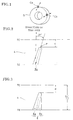
- the green tire G is supported so as to rotate and one side of a tread 4 thereof is carved using two cutters Ca, Cb.
- the cutters Ca, Cb have edges charged with electric current to be superheated and carve the tread rubber melting it. Shapes of the edges of the cutters Ca, Cb are somewhat different from each other and cutting angles are also different from each other.
- the cutters Ca, Cb carve the same place partly overlapping each other for forming one carved groove 8.
- TC and TE denote a tread center and a tread end, respectively.
- Fig. 2 shows a carved groove 8a formed on the surface of the tread 4 using the cutter Ca.
- the carved groove 8a is formed so as to elongate from a position distant from the tread center TC by a distance d (neighborhood of a closed end point P of a lug groove 9 (see Fig. 6)) to the dread end TE substantially in direction of the lug groove (direction inclined about 30 degrees to an axis of the tire).
- Fig. 3 shows the carved groove 8a and a carved groove 8b formed overlapping the groove 8a.
- the carved groove 8b extends from a midway of the carved groove 8a to the tread end TE substantially in parallel with axis of the tire so that a triangular carved groove 8 is formed by both carved grooves 8a, 8b.
- the carved groove 8a may be formed after the carved groove 8b is formed.
- the grooves 8a, 8b can be carved starting from the neighborhood of the closed end portion P of the lug groove 9 or toward the closed end point P.
- a most suitable covering direction can be selected in accordance with conditions of the equipment.
- the carved groove 8 is formed in a triangle gradually widening from the side of the tread center TC toward the tread end TE and opening continuously from a circumferential surface of the tread 4 to a side surface of the tread end.
- Such carved grooves 8 are formed using the cutters Ca, Cb on the tread 4 of the green tire G in a circumferential direction at regular intervals. Thus, the carved groove opened gradually widening can be formed without using a special cutter. After the carved grooves 8 have been formed on one side of the tread 4, similar carved grooves 8 are formed on another side of the tread 4.
- Fig. 4 shows a green tire G formed with the carved grooves 8 in the above-mentioned manner.
- the carved grooves 8 are formed from a position apart from the tread center TC by a distance d to the tread end TE, and the distance d is set at a value larger than 0.1 times of the tread width D.
- the green tire G is charged in a full-mold vulcanization-molding machine 10 for vulcanization-molding.
- the full-mold vulcanization-molding machine 1 has a half-sprit mold consisting of an upper mold 11 and a lower mold 12 as shown in Fig.5 schematically.
- the lower mold 12 is fixed with the mold face turned upward, and above the lower mold 12 is supported the upper mold 11 movably upward and downward with the mold face turned downward.
- the upper mold 11 is supported so as to freely rotate about a vertical axis.
- the upper and lower molds 11, 12 have respective slide guides 13, 14 projecting opposite to each other.
- the slide guides 13, 14 have respective slide faces coming into sliding contact with each other.
- the slide face is formed by a curved or straight surface inclined substantially in parallel with the lug groove.
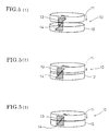
- the upper mold 11 and the lower mold 12 are joined with each other putting the green tire G between them for vulcanization-molding. At that time, a shown in Fig. 5(1), the upper mold 11 comes down to the fixed lower mold 12 until the slide face of the slide guide 13 of the upper mold 11 touches the slide face of the slide guide 14 of the lower mold 12.
- the upper mold 11 approaches the lower mold 12 rotating and the molds 11, 12 are joined together surely at a predetermined relative position. Since the upper and lower molds 11, 12 are in a predetermined positional relation that angles of the carved groove and the lug groove rib are coincide with each other when the molds 11, 12 are joined together, if the green tire G is charged in a predetermined relation to the molds 11, 12, the lug groove ribs of the upper and lower molds 11, 12 coincide with the carved groove 8 formed on the green tire G surely.
- the lug groove ribs of the upper and lower molds 11, 12 can be fitted to the carved grooves 8 of the green tire surely and enter the grooves 8 easily by rotating the upper mold 11, when the green tire is charged in a predetermined positional relation to the upper and lower molds 11, 12 and the upper mold 11 descends to close.
- the closed upper and lower molds 11, 12 can be opened smoothly without interference with the tread rubber.
- Fig. 6 shows a positional relation between the carved groove 8 and the lug groove 9 formed by the lug groove rib.
- the carved groove 8 is shown by the broken line and the lug groove is shown by the solid line.
- the lug groove 9 overlaps the triangular carved groove 8.
- the carved groove 8 is carved starting from the neighborhood of the closed end point P which is a tip end near the tread center TC of the lug groove 9 to be formed by vulcanization molding.
- the lug groove rib of the mold touches the green tire firstly at the closed end point P of the lug groove 9 when the mold is closed, and the carved groove 8 is carved in a shape opened from the neighborhood of the closed end point P of the lug groove 9 to the tread end TE, therefore the lug groove ribs enter the carved grooves 8 smoothly when the mold is closed and specific lug grooves can be formed accurately.
- the carved groove 8 is formed on a surface of the green tire extending about perpendicularly to the circumferential direction from the neighborhood of the closed end point P distant from the tread center TC by a distance larger than 0.1 times of the tread width to the tread end TE. Therefore, the carving work can be carried out easily.
- the direction of the main part of the lug groove 9 is inclined about 30 degrees to the direction of the tire axis, and the direction of the longer carved groove 8a coincides with the direction of the lug groove.
- the inclination angle of the lug groove to the tire axis is 5 degrees and more, and 45 degrees and less, when the upper mold is joined with the lower mold while rotating on vulcanization-molding, the lug groove ribs of the upper and lower molds easily enters the carved grooves of the green tire G while turning, and a specific lug groove 9 can be formed accurately.
- the volume of the carved groove 8 is selected so as to be within the limits of 0.4 - 1.2 times of the volume of the lug groove 9 to be formed by vulcanization-molding. If the volume of the carved groove 8 is smaller than 0.4 times of the volume of the lug groove 9, amount of rubber displaced by the lug groove rib of the mold on vulcanization-molding is too much so that pressing force by the lug groove rib is large and the belt wave by the pressing force acting on the belt 3 inside of the tread 4 is generated greatly.
- the belt wave can be restrained small as far as possible as shown in Fig. 7. Further, also unevenness of the belt gauge can be restrained small as far as possible and joining of the joint portion of the belt 3 is also ensured. As mentioned above, by forming the carved groove 8 starting from the neighborhood of the closed end point P of the lug groove 9, the belt wave can be made small further.
- the volume of the carved groove is 0.7 - 1.0 times of the volume of the lug groove, the amount of rubber displaced by the lug groove rib of the mold on vulcanization-molding is little, the lug groove rib cuts into the tread rubber easily and pressing force by the lug groove rib is small, so that the belt wave and unevenness of the belt gauge by the pressing force acting on the belt member inside of the tread rubber can be restrained to a minimum, joining of the joint portion can be ensured much more and poor vulcanization caused by generation of the bear can be prevented surely.
- Depth of the carved groove 8 is set to be 0.5 - 0.9 times of depth of the lug groove. If depth of the carved groove 8 is smaller than 0.5 times of depth of the lug groove, amount of rubber displaced by the lug groove rib on vulcanization-molding is too much. If depth of the carved groove 8 is larger than 0.9 times of depth of the lug groove, a gap between the carved groove and the lug groove rib is so large that the bear is apt to be generated and poor vulcanization is caused similarly to the above case regarding volume. These problems can be solved by selecting depth of the carved groove to 0.5 - 0.9 times of depth of the lug groove.
- a large-sized ORR tire 1 for a construction vehicle shown in Fig. 8 is manufactured.
- a plurality of lug grooves 9 each extending from a position of the tread near the tread center TC to the tread end TE are formed at regular intervals.
- the green tire G can be vulcanization-molded using the full-mold vulcanizing-molding machine 10. Therefore, compared with a customary vulcanization-molding machine with split molds, construction of the vulcanization-molding machine itself is simple, the installation space is small and the equipment cost can be reduced greatly.
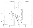
- Figs. 9 to 11 show another example having straight guide faces.
- an upper mold 31 moves up and down relatively to a lower mold 32 while rotating about a vertical axis for opening and closing.
- the upper mold 31 has an opening end edge projecting downward which is enlarged radially to form an engaging edge section 31a.
- the engaging edge section 31a engages with an opening end of the lower mold 32 projecting upward covering it from the outside so that the upper and lower molds 31, 32 are aligned and joined with each other.
- an upper mold slide guide 33 which is shaped in a triangle with rounded corners.
- the upper mold slide guide 33 has a taper section of angle of about 25 degrees directed downward and an inclined side forming a slide face 33a which is inclined about 25 degrees to a vertical central axis of the mold or the tire axis.
- the lower mold slide guide 34 has a lower end portion bolted to the lower mold 32.
- the lower mold slide guide 34 has a shape of right-angled triangle similar to that of the upper mold slide guide 33 and is more than twice as large as the upper mold slide guide 33.
- the lower mold slide guide 34 has a shortest side bolted and a taper section of angle of about 25 degrees projecting upward.
- the inclined side of the lower mold slide guide 34 forms a slide face 34a inclined about 25 degrees to the tire axis.
- the slide face 34a is opposite to the slide face 33a of the upper mold slide guide 33 for sliding contact.
- the above inclination angle of about 25 degrees of the slide faces 33a, 34a is equal to the angle of the lug groove ribs 36, 37 (Fig. 10) formed on inner surfaces of the upper and lower molds 31, 32.
- the lower mold 32 is provided with a stopper 35 side by side with the lower mold slide guide 34.
- the stopper 35 is bolted at the lower end portion and projected upward similarly to the lower mold slide guide 34.
- the stopper is contacted with the left end of the lower side of the lower mold slide guide 34 and has a side face on the side of the lower mold slide guide 34 forming a vertical face 35a. Therefore, the inclined slide face 34a of the lower mold slide guide 34 and the vertical surface of the stopper 35 form a wedge-shaped recess opened upward.
- center alignment of the molds 31, 32 are carried out in such a manner that the engaging edge section 31a of the upper mold 31 covers the upper end opening edge of the lower mold 32 from the outside.
- the upper mold 31 is rotated while descending as the slide faces 33a, 34a of the upper and lower mold slide guides 33, 34 slide along each other, and finally the upper mold 31 is joined with the lower mold 31.
- the upper mold slide guide 33 is fitted into the wedge-shaped recess between the lower mold slide guide 34 and the stopper 35 to rotationally position the upper mold 31 relatively to the lower mold 32.
- the lug groove ribs 36, 37 directed in the same direction as the inclination angle of the slide faces 33a, 34a are fitted in the carved grooves 8 of the green tire G smoothly without being obstructed by the tread rubber, so that a specific lug groove can be formed accurately.
- Fig. 12 shows another example in which the inclination angle of the slide surface is different from that of the above example. Namely, the slide faces 43a, 44a of the upper and lower mold slide guides 43, 44 are inclined about 40 degrees to the tire axis.
- the lug groove ribs on inner faces of the upper and lower molds are also inclined about 40 degrees to the tire axis.
- the lug groove rib is fitted in the carved groove of the green tire smoothly and a lug groove having a inclination angle of 40 degrees to the tire axis is formed with a high accuracy.
- a stopper 45 is attached to the lower mold 42 in contact with the lower mold slide guide 44.
Landscapes
- Engineering & Computer Science (AREA)
- Mechanical Engineering (AREA)
- Heating, Cooling, Or Curing Plastics Or The Like In General (AREA)
- Moulds For Moulding Plastics Or The Like (AREA)
- Tyre Moulding (AREA)
- Tires In General (AREA)
Abstract
Description
Claims (18)
- A method for manufacturing a pneumatic tire (1) in which a green tire (G) having assembled tire components is charged into a mold (10) for vulcanization-molding and lug grooves (9) are formed in a tire tread surface (4), said method including previously forming carved grooves (8) at positions in a surface of said green tire (G) corresponding to said lug grooves (9) extending in substantially the same direction as said lug grooves.
- A method as claimed in claim 1, characterized in that said carved groove (8) is carved in a shape opened from a tread center side (TC) to a tread end (TE).
- A method as claimed in claim 2, characterized in that said carved groove (8) is carved in a shape opened from the neighbourhood of a closed end point (P) of said lug groove (9) to said tread end (TE).
- A method as claimed in claim 3, characterized in that said closed end point (P) of said lug groove (9) is distant from the tread center (TC) by a distance larger than 0.1 times of a tread width (D).
- A method as claimed in any of claims 1 to 4, characterized in that a main part of said lug groove (9) is inclined with regard to the axis of the tire at an angle of 5 degrees or more to 45 degrees or less.
- A method as claimed in claim 1, characterized in that said carved groove (8) is carved in a shape opened from one tread end (TE) to another tread end.
- A method as claimed in any of claims 1 to 5, characterized in that said carved groove (8) is carved in a shape opened from a tread center side (TC) to a tread end (TE) gradually widening.
- A method as claimed in claim 7, characterized in that said carved groove (8) having said gradually widening shape is formed by carrying out the carving twice using a cutter (C).
- A method as claimed in claim 6, 7 or 8, characterized in that said carved groove (8) is carved along the direction of said lug groove (9) and along the direction of the axis of the tire from or toward the neighbourhood of a closed end point (P) of said lug groove (9).
- A method as claimed in any of claims 1 to 9, characterized in that the volume of said carved groove (8) is 0.4 - 1.2 times the volume of said lug groove (9).
- A method as claimed in claim 10, characterized in that the volume of said carved groove (8) is 0.7 - 1.0 times the volume of said lug groove (9).
- A method as claimed in any of claims 1 to 11, characterized in that the depth of said carved groove (8) is 0.5 - 0.9 times the depth of said lug groove (9).
- A method as claimed in any of claims 1 to 12, characterized in that said tire components include a belt member (3) having a relatively low expansion rate.
- A method as claimed in claim 13, characterized in that expansion rate of said belt member (3) is 3% or less.
- A method as claimed in any of claims 1 to 14, characterized in that a full-mold vulcanization-molding machine (10) having an upper mold (11) and a lower mold (12) is used as a mold for vulcanizing and molding said green tire (G).
- A method as claimed in claim 15, characterized in that lug groove ribs on said upper and lower molds (11,12) are fitted in said carved groove (8) of said green tire (G) when said green tire is charged in said full-mold vulcanization-molding machine (10).
- A method for manufacturing a pneumatic tire (1), comprising: a step of manufacturing a green tire (G) in which ribbon-like or sheet-like extruded rubber is piled up on a ply and a belt member (3) assembled on a drum to form a tread (4); a step of forming a carved groove (8) in a tread surface of said green tire (G) in a direction of a lug groove (9); and a step of charging said green tire (G) formed with said carved groove (8) in a vulcanization-molding machine (10) to carry out vulcanization-molding.
- An apparatus for manufacturing a pneumatic tire (1) which is a full-mold vulcanization-molding machine (10) having an upper mold (11) and a lower mold (12) each provided with lug groove ribs, and guide means (13,14) provided on said molds (11,12) for letting said lug groove ribs fit to a carved groove (8) formed in a green tire (G) when said green tire is charged in said full-mold vulcanization-molding machine (10).
Applications Claiming Priority (4)
| Application Number | Priority Date | Filing Date | Title |
|---|---|---|---|
| JP22120099 | 1999-08-04 | ||
| JP22120099 | 1999-08-04 | ||
| JP2000202211A JP4702982B2 (en) | 1999-08-04 | 2000-07-04 | Pneumatic tire manufacturing equipment |
| JP2000202211 | 2000-07-04 |
Publications (3)
| Publication Number | Publication Date |
|---|---|
| EP1074379A2 true EP1074379A2 (en) | 2001-02-07 |
| EP1074379A3 EP1074379A3 (en) | 2002-04-24 |
| EP1074379B1 EP1074379B1 (en) | 2006-06-07 |
Family
ID=26524150
Family Applications (1)
| Application Number | Title | Priority Date | Filing Date |
|---|---|---|---|
| EP00306662A Expired - Lifetime EP1074379B1 (en) | 1999-08-04 | 2000-08-04 | Method and apparatus for manufacturing pneumatic tires |
Country Status (4)
| Country | Link |
|---|---|
| US (1) | US6802922B1 (en) |
| EP (1) | EP1074379B1 (en) |
| JP (1) | JP4702982B2 (en) |
| ES (1) | ES2265872T3 (en) |
Cited By (1)
| Publication number | Priority date | Publication date | Assignee | Title |
|---|---|---|---|---|
| EP1186402A3 (en) * | 2000-09-07 | 2003-10-01 | Bridgestone Corporation | Method and apparatus for forming carved grooves on green tires |
Families Citing this family (6)
| Publication number | Priority date | Publication date | Assignee | Title |
|---|---|---|---|---|
| JP2007216829A (en) * | 2006-02-16 | 2007-08-30 | Bridgestone Corp | Tire for construction vehicle, and its manufacturing method |
| JP5094103B2 (en) * | 2006-12-12 | 2012-12-12 | 株式会社ブリヂストン | Pneumatic tire |
| US8061398B2 (en) * | 2008-02-25 | 2011-11-22 | Chemtura Corporation | Non-pneumatic tire having angled tread groove wall |
| US8056593B2 (en) * | 2007-10-26 | 2011-11-15 | Chemtura Corporation | Non-pneumatic tire |
| JP5371231B2 (en) * | 2007-11-27 | 2013-12-18 | 株式会社ブリヂストン | Tire vulcanization mold |
| CN106891675A (en) * | 2017-04-07 | 2017-06-27 | 黄丽 | A kind of full zero degree tire with steel belt |
Family Cites Families (28)
| Publication number | Priority date | Publication date | Assignee | Title |
|---|---|---|---|---|
| US2245728A (en) * | 1939-12-20 | 1941-06-17 | Harry E Sipe | Device for circumferentially grooving tire surfaces |
| US2402430A (en) * | 1943-06-16 | 1946-06-18 | Us Rubber Co | Method of making rubber articles |
| NL135522B (en) * | 1965-07-31 | |||
| US3502131A (en) * | 1967-03-14 | 1970-03-24 | Nat Standard Co | Apparatus for cutting tread patterns in built-up tires |
| DE1901130A1 (en) * | 1969-01-10 | 1970-07-23 | Herbert Maschf L | Press mold for vulcanizing vehicle tires |
| BE786350A (en) * | 1971-08-02 | 1973-01-17 | Michelin & Cie | DEVICE FOR CARVING THE TIRE ENVELOPES |
| DE2301414A1 (en) * | 1973-01-12 | 1974-07-18 | Brunotte & Niemeyer Maschinenf | Tyre press with simple extraction - having lower half of mould free to rotate when press is opened |
| US3980120A (en) * | 1975-02-04 | 1976-09-14 | Kennametal Inc. | Method and apparatus for removing tread material from radial belted tires |
| US4081017A (en) | 1976-09-27 | 1978-03-28 | The Goodyear Tire & Rubber Company | Apparatus for grooving tires |
| US4080230A (en) * | 1976-11-01 | 1978-03-21 | Rubber Machines, Systems Inc. | Method and automated system for retreading tires |
| JPS5369304A (en) * | 1976-12-03 | 1978-06-20 | Bridgestone Corp | Low-noise pneumatic tire |
| JPS53116601A (en) * | 1977-03-12 | 1978-10-12 | Toyo Tire & Rubber Co Ltd | High speed tire for construction vehicle |
| FR2388685A1 (en) * | 1977-04-28 | 1978-11-24 | Michelin & Cie | TIRE PERFECTION |
| US4237955A (en) * | 1979-01-25 | 1980-12-09 | Brad Ragan, Inc. | Apparatus and method for grooving tires |
| JPS5930562B2 (en) * | 1979-08-03 | 1984-07-27 | 住友ゴム工業株式会社 | low noise pneumatic tires |
| US4308083A (en) * | 1980-03-26 | 1981-12-29 | The Goodyear Tire & Rubber Company | Pneumatic tire and method of building a pneumatic tire |
| JPS60230832A (en) * | 1984-05-01 | 1985-11-16 | Bridgestone Corp | Preparation of pneumatic radial tire |
| JPS60212336A (en) * | 1984-04-09 | 1985-10-24 | Bridgestone Corp | Method and apparatus for manufacturing high-lug tire |
| JPS613711A (en) * | 1984-06-18 | 1986-01-09 | Bridgestone Corp | Vulcanization molding method of pneumatic tire |
| JPS61273937A (en) * | 1985-05-30 | 1986-12-04 | Bridgestone Corp | Preparation of pneumatic tire having deep-grooved lug |
| JPS6274635A (en) * | 1985-09-30 | 1987-04-06 | Bridgestone Corp | Shaping device for tire |
| JPS6322703A (en) * | 1986-07-15 | 1988-01-30 | Bridgestone Corp | Pneumatic tyre |
| JPH07115427B2 (en) * | 1986-10-09 | 1995-12-13 | 株式会社ブリヂストン | Tire shaving device |
| JPH01163051A (en) * | 1987-12-19 | 1989-06-27 | Sumitomo Rubber Ind Ltd | Grooving apparatus |
| JPH0428509A (en) * | 1990-05-24 | 1992-01-31 | Ohtsu Tire & Rubber Co Ltd :The | Manufacture of pneumatic tire having tread having projection such as lug, and block in tread |
| JPH05229312A (en) * | 1992-02-20 | 1993-09-07 | Bridgestone Corp | Pneumatic rug tires |
| JPH06127213A (en) * | 1992-10-14 | 1994-05-10 | Bridgestone Corp | Radial tires for heavy loads |
| JP4726286B2 (en) * | 2000-09-07 | 2011-07-20 | 株式会社ブリヂストン | Raw tire excavation groove forming method and apparatus |
-
2000
- 2000-07-04 JP JP2000202211A patent/JP4702982B2/en not_active Expired - Fee Related
- 2000-08-04 EP EP00306662A patent/EP1074379B1/en not_active Expired - Lifetime
- 2000-08-04 US US09/633,336 patent/US6802922B1/en not_active Expired - Lifetime
- 2000-08-04 ES ES00306662T patent/ES2265872T3/en not_active Expired - Lifetime
Cited By (2)
| Publication number | Priority date | Publication date | Assignee | Title |
|---|---|---|---|---|
| EP1186402A3 (en) * | 2000-09-07 | 2003-10-01 | Bridgestone Corporation | Method and apparatus for forming carved grooves on green tires |
| US6951235B2 (en) | 2000-09-07 | 2005-10-04 | Bridgestone Corporation | Method and apparatus for forming carved groove of green tire |
Also Published As
| Publication number | Publication date |
|---|---|
| EP1074379B1 (en) | 2006-06-07 |
| US6802922B1 (en) | 2004-10-12 |
| JP4702982B2 (en) | 2011-06-15 |
| ES2265872T3 (en) | 2007-03-01 |
| JP2001105511A (en) | 2001-04-17 |
| EP1074379A3 (en) | 2002-04-24 |
Similar Documents
| Publication | Publication Date | Title |
|---|---|---|
| EP2632702B1 (en) | A tire tread with apertures and a method for the manufacture of a tire tread with apertures | |
| US6802922B1 (en) | Method and apparatus for manufacturing pneumatic tire | |
| EP3102399B1 (en) | Expandable belt and tread drum with varied curvature segments | |
| KR101929054B1 (en) | Solid deck bead lock drum | |
| JP6826432B2 (en) | Tire vulcanization mold and pneumatic tire | |
| US20200101682A1 (en) | Transfer ring with block and rail system | |
| JP2001353725A (en) | Tread mold | |
| JP3568321B2 (en) | Pneumatic tire and mold for molding the tire | |
| EP0559964A1 (en) | Process and apparatus for manufacturing tires with white sidewall appliques | |
| EP2522496B1 (en) | Method for manufacturing a tire with a colored sidewall and tire with a colored sidewall | |
| JP2009149300A (en) | Tire, tire vulcanization method, mold manufacturing method and mold matrix | |
| EP4292801B1 (en) | Tire mold | |
| JP4603709B2 (en) | Tire vulcanization mold and tire manufacturing method | |
| JPH09254274A (en) | Method and apparatus for manufacturing rehabilitation green tire | |
| KR20100099296A (en) | Apparatus for vulcanization and moulding of tyres and method for manufacturing the same | |
| US7479196B2 (en) | Method for manufacturing or retreading a pneumatic tire | |
| EP0302935B1 (en) | Radial tire for aircraft and manufacturing method thereof | |
| GB2341339A (en) | Improvements to tyre moulds | |
| JP2001129831A (en) | Mold for tire vulcanization molding | |
| JP3079058B2 (en) | Tire vulcanizing mold and molding method using the same | |
| CN109016587B (en) | Retractable device and tire mold | |
| US11214028B2 (en) | Tire vulcanizing apparatus and tire vulcanizing method | |
| JP7131196B2 (en) | Tire mold and tire manufacturing method | |
| JP2004244016A (en) | Truck steering tire, mold, and molding method | |
| JPS621210Y2 (en) |
Legal Events
| Date | Code | Title | Description |
|---|---|---|---|
| PUAI | Public reference made under article 153(3) epc to a published international application that has entered the european phase |
Free format text: ORIGINAL CODE: 0009012 |
|
| AK | Designated contracting states |
Kind code of ref document: A2 Designated state(s): ES FR LU Kind code of ref document: A2 Designated state(s): AT BE CH CY DE DK ES FI FR GB GR IE IT LI LU MC NL PT SE |
|
| AX | Request for extension of the european patent |
Free format text: AL;LT;LV;MK;RO;SI |
|
| PUAL | Search report despatched |
Free format text: ORIGINAL CODE: 0009013 |
|
| AK | Designated contracting states |
Kind code of ref document: A3 Designated state(s): AT BE CH CY DE DK ES FI FR GB GR IE IT LI LU MC NL PT SE |
|
| AX | Request for extension of the european patent |
Free format text: AL;LT;LV;MK;RO;SI |
|
| 17P | Request for examination filed |
Effective date: 20020605 |
|
| AKX | Designation fees paid |
Free format text: ES FR LU |
|
| REG | Reference to a national code |
Ref country code: DE Ref legal event code: 8566 |
|
| 17Q | First examination report despatched |
Effective date: 20040115 |
|
| GRAP | Despatch of communication of intention to grant a patent |
Free format text: ORIGINAL CODE: EPIDOSNIGR1 |
|
| GRAS | Grant fee paid |
Free format text: ORIGINAL CODE: EPIDOSNIGR3 |
|
| GRAA | (expected) grant |
Free format text: ORIGINAL CODE: 0009210 |
|
| AK | Designated contracting states |
Kind code of ref document: B1 Designated state(s): ES FR LU |
|
| ET | Fr: translation filed | ||
| REG | Reference to a national code |
Ref country code: ES Ref legal event code: FG2A Ref document number: 2265872 Country of ref document: ES Kind code of ref document: T3 |
|
| PLBE | No opposition filed within time limit |
Free format text: ORIGINAL CODE: 0009261 |
|
| STAA | Information on the status of an ep patent application or granted ep patent |
Free format text: STATUS: NO OPPOSITION FILED WITHIN TIME LIMIT |
|
| 26N | No opposition filed |
Effective date: 20070308 |
|
| REG | Reference to a national code |
Ref country code: FR Ref legal event code: CA Effective date: 20140812 |
|
| PGFP | Annual fee paid to national office [announced via postgrant information from national office to epo] |
Ref country code: LU Payment date: 20140822 Year of fee payment: 15 |
|
| PGFP | Annual fee paid to national office [announced via postgrant information from national office to epo] |
Ref country code: FR Payment date: 20140821 Year of fee payment: 15 Ref country code: ES Payment date: 20140826 Year of fee payment: 15 |
|
| PG25 | Lapsed in a contracting state [announced via postgrant information from national office to epo] |
Ref country code: LU Free format text: LAPSE BECAUSE OF NON-PAYMENT OF DUE FEES Effective date: 20150804 |
|
| REG | Reference to a national code |
Ref country code: FR Ref legal event code: ST Effective date: 20160429 |
|
| PG25 | Lapsed in a contracting state [announced via postgrant information from national office to epo] |
Ref country code: FR Free format text: LAPSE BECAUSE OF NON-PAYMENT OF DUE FEES Effective date: 20150831 |
|
| REG | Reference to a national code |
Ref country code: ES Ref legal event code: FD2A Effective date: 20160926 |
|
| PG25 | Lapsed in a contracting state [announced via postgrant information from national office to epo] |
Ref country code: ES Free format text: LAPSE BECAUSE OF NON-PAYMENT OF DUE FEES Effective date: 20150805 |