EP1074224A2 - Surgical instrument and method for endoscopic tissue dissection - Google Patents
Surgical instrument and method for endoscopic tissue dissection Download PDFInfo
- Publication number
- EP1074224A2 EP1074224A2 EP00306566A EP00306566A EP1074224A2 EP 1074224 A2 EP1074224 A2 EP 1074224A2 EP 00306566 A EP00306566 A EP 00306566A EP 00306566 A EP00306566 A EP 00306566A EP 1074224 A2 EP1074224 A2 EP 1074224A2
- Authority
- EP
- European Patent Office
- Prior art keywords
- optical
- surgical instrument
- tip
- hollow shaft
- endoscope
- Prior art date
- Legal status (The legal status is an assumption and is not a legal conclusion. Google has not performed a legal analysis and makes no representation as to the accuracy of the status listed.)
- Granted
Links
- 238000000034 method Methods 0.000 title abstract description 34
- 238000002224 dissection Methods 0.000 title description 6
- 230000003287 optical effect Effects 0.000 claims abstract description 117
- 230000000149 penetrating effect Effects 0.000 claims abstract description 29
- 238000010926 purge Methods 0.000 claims description 9
- CURLTUGMZLYLDI-UHFFFAOYSA-N Carbon dioxide Chemical compound O=C=O CURLTUGMZLYLDI-UHFFFAOYSA-N 0.000 claims description 8
- 239000013618 particulate matter Substances 0.000 claims description 5
- 229910002092 carbon dioxide Inorganic materials 0.000 claims description 4
- 239000001569 carbon dioxide Substances 0.000 claims description 4
- 239000000463 material Substances 0.000 claims 1
- 238000003306 harvesting Methods 0.000 abstract description 14
- 210000001519 tissue Anatomy 0.000 description 33
- 210000004204 blood vessel Anatomy 0.000 description 23
- 210000003752 saphenous vein Anatomy 0.000 description 12
- 210000003462 vein Anatomy 0.000 description 7
- 239000012530 fluid Substances 0.000 description 6
- 238000001356 surgical procedure Methods 0.000 description 6
- 210000004351 coronary vessel Anatomy 0.000 description 3
- 230000035515 penetration Effects 0.000 description 3
- 238000012800 visualization Methods 0.000 description 3
- 238000009833 condensation Methods 0.000 description 2
- 230000005494 condensation Effects 0.000 description 2
- 238000003780 insertion Methods 0.000 description 2
- 230000037431 insertion Effects 0.000 description 2
- 239000003595 mist Substances 0.000 description 2
- 206010033675 panniculitis Diseases 0.000 description 2
- 239000004033 plastic Substances 0.000 description 2
- 239000000779 smoke Substances 0.000 description 2
- 210000004304 subcutaneous tissue Anatomy 0.000 description 2
- 230000005641 tunneling Effects 0.000 description 2
- 210000002808 connective tissue Anatomy 0.000 description 1
- 230000007423 decrease Effects 0.000 description 1
- 239000012636 effector Substances 0.000 description 1
- -1 for example Substances 0.000 description 1
- 238000005286 illumination Methods 0.000 description 1
- 238000002347 injection Methods 0.000 description 1
- 239000007924 injection Substances 0.000 description 1
- 239000003550 marker Substances 0.000 description 1
- 239000000203 mixture Substances 0.000 description 1
- 230000008520 organization Effects 0.000 description 1
- 239000004417 polycarbonate Substances 0.000 description 1
- 229920000515 polycarbonate Polymers 0.000 description 1
- 229910001220 stainless steel Inorganic materials 0.000 description 1
- 239000010935 stainless steel Substances 0.000 description 1
- 238000007920 subcutaneous administration Methods 0.000 description 1
- 238000006467 substitution reaction Methods 0.000 description 1
- XLYOFNOQVPJJNP-UHFFFAOYSA-N water Substances O XLYOFNOQVPJJNP-UHFFFAOYSA-N 0.000 description 1
Images



Classifications
-
- A—HUMAN NECESSITIES
- A61—MEDICAL OR VETERINARY SCIENCE; HYGIENE
- A61B—DIAGNOSIS; SURGERY; IDENTIFICATION
- A61B17/00—Surgical instruments, devices or methods
- A61B17/00008—Vein tendon strippers
-
- A—HUMAN NECESSITIES
- A61—MEDICAL OR VETERINARY SCIENCE; HYGIENE
- A61B—DIAGNOSIS; SURGERY; IDENTIFICATION
- A61B17/00—Surgical instruments, devices or methods
- A61B17/34—Trocars; Puncturing needles
- A61B17/3417—Details of tips or shafts, e.g. grooves, expandable, bendable; Multiple coaxial sliding cannulas, e.g. for dilating
-
- A—HUMAN NECESSITIES
- A61—MEDICAL OR VETERINARY SCIENCE; HYGIENE
- A61B—DIAGNOSIS; SURGERY; IDENTIFICATION
- A61B90/00—Instruments, implements or accessories specially adapted for surgery or diagnosis and not covered by any of the groups A61B1/00 - A61B50/00, e.g. for luxation treatment or for protecting wound edges
- A61B90/30—Devices for illuminating a surgical field, the devices having an interrelation with other surgical devices or with a surgical procedure
-
- A—HUMAN NECESSITIES
- A61—MEDICAL OR VETERINARY SCIENCE; HYGIENE
- A61B—DIAGNOSIS; SURGERY; IDENTIFICATION
- A61B90/00—Instruments, implements or accessories specially adapted for surgery or diagnosis and not covered by any of the groups A61B1/00 - A61B50/00, e.g. for luxation treatment or for protecting wound edges
- A61B90/36—Image-producing devices or illumination devices not otherwise provided for
- A61B90/361—Image-producing devices, e.g. surgical cameras
Definitions
- the present invention relates, in general, to the dissection and retraction of bodily tissue and, more particularly, to new devices and endoscopic methods for harvesting a blood vessel to be used as a coronary artery bypass graft.
- Minimally invasive vessel harvesting has gained widespread acceptance in the field of surgery as a method for obtaining graft vessels for coronary artery bypass graft (CABG) procedures.
- CABG coronary artery bypass graft
- a long portion of the saphenous vein is removed from a patient's leg, operating through only one or a small number of short incisions in the leg.
- the vein is then segmented according to the number and type of grafts needed for the CABG procedure.
- a surgical technique for the removal of a vessel such as a saphenous vein is disclosed in U.S. Patent Re. 36, 043 issued to Knighton on January 12, 1999 (hereinafter, Knighton).
- the surgeon uses an endoscope having a lumen through it.
- a grasping instrument is inserted in the lumen in order to grasp the saphenous vein, which is then withdrawn into the lumen of the endoscope.
- the endoscope is maneuvered along the length of the vein while side branches of the vein are ligated and transected whenever encountered.
- the illumination within the subcutaneous space created by this type of endoscope is also limited to the light emitted directly at the distal portion of the endoscope.
- a third drawback to the described method is that the side branches of the saphenous vein limit the maneuverability of the endoscope. This limited maneuverability is because the outer edge of the endoscope body is prevented from advancing along the trunk of the saphenous vein until the encountered side branches are ligated and transected. Once free, the endoscope is then maneuvered until the next side branch is encountered.
- Ethicon Endo-Surgery, Inc. Cincinnati, Ohio, has developed and promoted two very successful devices and an associated method for endoscopically harvesting blood vessels such as the saphenous vein.
- a surgeon or surgical assistant uses an optical tissue dissector known as the ENDOPATH SUBCU-DISSECTOR optical dissector for separating subcutaneous tissue away from the saphenous vein.
- the surgeon or assistant uses an optical retractor known as the ENDOPATH SUBCU-RETRACTOR optical retractor for retracting the dissected tissue away from the saphenous vein.
- Both of these devices have a transparent, concave working head having a spoon shape.
- the optical retractor has a larger, working head, however, than the optical dissector.
- the concave, working head defines a working space for the end effectors of an instrument such as a grasper, a scissors, or a clip applier.
- the optical dissector and optical retractor allow the surgeon to see the tissue on which is operated.
- These devices hereinafter, Knight devices, Knight optical dissector, Knight optical retractor
- a surgical method for their use have been issued to Knight, et al, and are disclosed in U.S. Patent 5,667,480 issued on September 16, 1997 and in U.S. Patent 5,722,934 issued on March 3, 1998, both of which are hereby incorporated herein by reference.
- the Knight optical dissector and retractor are each used with a thirty-degree endoscope in which the viewing angle of the distal end of the scope is slanted 30 degrees from the longitudinal axis of the instrument. The field of view is therefore directed ahead and to one side of the axis.
- This type of endoscope is ideal for use with the spoon shaped heads of the Knight devices because the surgeon desires to view the tissue directly ahead of the head and beneath the opening of the head where the tissue may be operated on.
- DuBois device for dissecting and retracting a blood vessel from subcutaneous tissue.
- the DuBois device is similar to either of the Knight devices, and has the addition of a fluid carrying system for purging particulate matter from the working space of the concave head of either the optical dissector or optical retractor.
- a fluid flow (of carbon dioxide gas, for example) is used to purge smoke and/or mist from the enclosed working space in order to maintain visualization of the tissue being operated on.
- Particulate matter accumulates due to the use of electrosurgical or ultrasonic cutting devices, whereas condensation of moisture in the working space occurs due to the temperature differential between the inside and outside of the patient's body.
- the Knight and DuBois devices and methods for their use for harvesting vessels represent a significant advance in the surgical art. Nevertheless, widespread use of these devices and methods has helped to clarify even more the needs of the surgeon for harvesting blood vessels. For example, for some surgeons or physician assistants, the repeated application of force required to advance the concave head of the Knight optical dissector in order to separate tissue from the vein can become physically tiring. This is especially true when harvesting a long (over 18 inches) portion of vein such as would be needed for a multiple CABG procedure. For these surgeons/assistants, the time required to dissect the vein can be several minutes longer than the time required by others who are better able to exert the manual dissection force required during the procedure.
- optical trocars In recent years, a number of penetrating optical instruments, sometimes referred to as optical trocars, have been developed for gaining access into a cavity in the surgical patient.
- optical trocars One of the earliest examples is disclosed in U.S. Patent 5,271,380 issued on December 21, 1993 to Riek, et al.
- This penetration instrument has a hollow shaft for receiving an endoscope, and a transparent, conical distal end.
- the apex or distal-most portion of the conical-shaped tip, lies on the central longitudinal axis of the instrument.
- These types of instruments are intended for use primarily with a zero-degree endoscope in which the field of view is directly ahead of the distal end of the endoscope.
- the apex is centered in the field of view, and it is possible to view images all around the apex within the field of view.
- the present invention is a surgical instrument for optically penetrating bodily tissue to create an initial body cavity.
- the surgical instrument comprises an elongated hollow shaft having a longitudinal axis, a proximal end, a distal end, and a lumen therethrough.
- the surgical instrument further comprises an optical penetrating tip having a cylindrical portion attached to the distal end of the hollow shaft and a tapered portion extending distally therefrom.
- the tapered portion has an apex spaced laterally apart from the longitudinal axis of the hollow shaft, thus allowing the surgeon to visualize all tissue adjacent to the tapered portion of the optical penetrating tip while being used in combination with an endoscope having a 30-degree tip.
- a handle is attached to the proximal end of the hollow shaft for manipulating the surgical instrument through an incision of the surgical patient.
- the tapered portion of the optical penetrating tip has an upper surface blended into a lower surface, and the upper surface is sloped with respect to the longitudinal axis of the hollow shaft.
- the upper surface has an average inclination axis when viewed from the side and the average inclination axis forms an inclination angle with the longitudinal axis of the hollow shaft of between 15 and 75 degrees.
- a preferred inclination angle is about 45 degrees.
- the surgical instrument further includes an endoscope for slidably insertion into the lumen of the hollow shaft.
- the endoscope has a conical field-of-view through the optical penetrating tip, whereby a central viewing axis of the field-of-view is directed thirty degrees from the longitudinal axis of the hollow shaft, and the apex of the optical penetrating tip is approximately in the center of the field-of-view of the endoscope.
- the surgical instrument further includes at least one purge port in the distal end of the hollow shaft fluidly connected to a flow source, such as carbon dioxide gas. Particulate matter and moisture is purged from a body cavity created by the optical penetrating tip while the surgical instrument is inserted in the body cavity.
- a flow source such as carbon dioxide gas.
- a method for creating an initial body cavity alongside of a vessel to be harvested from a surgical patient's body comprising the steps of identifying a vessel to be removed, making an incision in the patient's body near the identified vessel, inserting a surgical instrument having an optical penetrating tip through the incision, optically penetrating the tissue along a side of the vessel with the optical penetrating instrument, and withdrawing the optical penetrating instrument from the body through the incision.
- FIG. 1 is a side, sectional view of a first embodiment of the present invention, an optical dissector 10 (also referred to as a surgical instrument).
- Optical dissector 10 is positioned through incision 1 and between upper tissue layer 2 and lower tissue layer 4 of a surgical patient, and is shown being used in combination with an endoscope 6 having a 30-degree tip 8 to create an initial body cavity 7 alongside blood vessel 3.
- Optical dissector 10 comprises a hollow, elongated shaft 20 having a distal end 22 and a proximal end 24.
- Shaft 20 is preferably made of stainless steel tubing.
- a plastic handle 12 for gripping and manipulating optical dissector 10 is attached to proximal end 24 of shaft 20.
- Handle 12 comprises an ergonomically shaped grip 18, a nose 14 for attachment to shaft 20, and a connector 16 for attaching optical dissector 10 to a flow source (not shown).
- Optical dissector 10 further comprises a hollow, transparent, optical tip 30 attached to distal end 22 of shaft 20.
- Endoscope 6 has an elongated, optical shaft 9 slidably inserted into shaft 20 so that a 30-degree tip 8 of endoscope 6 is positioned inside of optical tip 30 of optical dissector 10.
- An endoscope retaining guide 17 is provided in handle 12 for holding and aligning stem 11 of endoscope 6 in an upright position as shown, so that 30-degree tip 8 of endoscope 6 is oriented in a downward position as shown. As will be described for Figure 15, this alignment of the endoscope 6 is advantageous for viewing tissues adjacent to optical tip 30.
- FIG 2 is an isometric view of optical tip 30, a first embodiment of the present invention and shown in Figure 1.
- Optical tip 30 is asymmetrically shaped and comprises a tapered portion 39 having an apex 32.
- Optical tip 30 further comprises a cylindrical portion 38 and a proximal end 34.
- Optical tip 30 is optically transparent and has a uniformly thick wall in tapered portion 39.
- Optical tip 30 is preferably made of a rigid, medical grade, injection moldable plastic such as polycarbonate.
- Figure 3 is an isometric view of proximal end 34 of optical tip 30, showing a lumen 29 therein for attachment to distal end 22 of shaft 20 shown in Figure 4.
- four dovetail shaped ribs 36 are formed in proximal end 34 of optical tip 30 for attachment to four shaft flutes 26 formed into distal end 22 of shaft 20.
- This type of attachment is not intended to be detachable by the user.
- Other types of attachments are possible, including those types in which the user may detach optical tip 30 from shaft 20. This may be advantageous, for example, for surgical procedures requiring multiple versions of optical tip 30, each version having dissecting and/or optical characteristics specifically provided for particular steps of the surgical procedure.
- Figure 4 shows a lumen 23 extending through the entire length of shaft 20 for slidably inserting endoscope 6.
- Figure 4 also shows a purge port 25 located proximal to where proximal end 34 of optical tip 30 would be positioned once assembled.
- At least one purge port 25 is provided and fluidly communicated to connector 16 of handle 12 as described for the DuBois device previously referenced in U.S. Patent 5,902,315.
- Purge port 25 allows a flow of fluid, such as carbon dioxide gas, to be introduced into body cavity 7 of the patient during the surgical procedure. The fluid then escapes body cavity 7 along the outside of shaft 20 and out of incision 1 (see Figure 1).
- This flow of fluid purges particulate matter including, for example, smoke and mist resulting from the use of electrosurgical or ultrasonic cutting instruments, which may be used in combination with optical dissector 10.
- This flow of fluid also helps to dry moisture forming on optical tip 30 due to condensation of water inside body cavity 7, thus improving the ability of the operator to view tissue adjacent to optical tip 30.
- Figure 5 is a top view
- Figure 6 is a side, sectional view
- Figure 7 is a bottom view of optical dissector 30 shown in Figures 1 and 2, assembled onto distal end 22 of shaft 20.
- Optical shaft 9 of endoscope 6 is shown slidably inserted into shaft 20.
- a curved, upper surface 31 (see Figure 5) of tapered portion 39 blends with a lower surface 35 (see Figure 7).
- Upper surface 31 and lower surface 35 are rounded or non-planar, that is, neither has a flattened area.
- a 30-degree tip 8 of endoscope 6 is positioned within an optical tip chamber 33 and is oriented to view ahead and downwardly.
- FIG. 14 shows a conical tip 60 having a distal point 63 centered on a longitudinal axis 50.
- Conical tip 60 is shown assembled onto distal end 22 of shaft 20, and used in combination with endoscope 6 for separating blood vessel 3, having side branch 5, from lower tissue layer 4.
- Endoscope 6 has 30-degree tip 8, which has a field-of-view 62 centered on a viewing axis 64.
- the width of field-of-view 62 shown is not limited to what is illustrated in Figure 14, and may be more or less depending on the optical characteristics of endoscope 6.
- Conical tip 60 is similar in shape to the optical trocar described in U.S.
- Patent 5,569,291 is representative of the symmetrically shaped optical tips of the prior art.
- side branch 5 and lower tissue layer 4 are not contained within the field-of-view 62 of endoscope 6. If endoscope 6 were rotated 180 degrees about axis 50 so that 30-degree tip 8 was pointed downwardly instead of upwardly, then blood vessel 3 would not be contained in field-of-view 62.
- endoscope 6 In order to view blood vessel 3, side branch 5, and lower tissue layer 4 simultaneously when using conical tip 60, therefore, endoscope 6 must be provided with a zero-degree tip (not shown). A zero-degree tip views "straight-ahead" in the distal direction, and would allow point 63 to be approximately centered within field-of-view 62.
- Figure 15 shows the distal portion of optical dissector 10 of Figure 6 used in combination with 30-degree tip 8 of endoscope 6 having an angled field-of-view 66 and an angled viewing axis 68.
- apex 32 of optical tip 30 is approximately in the center of angled field-of-view 66 and closely aligned with an angled viewing axis 68.
- a viewing angle 67 is between angled viewing axis 68 and longitudinal axis 50.
- Blood vessel 3 and side branch 5 are also contained in angled field-of-view 66. The user may, therefore, advance optical dissector 10 while visualizing both blood vessel 3 and lower tissue layer 4 as they are separated. The user is also able to see side branch 5 as it is encountered.
- the profile of upper surface 31 is shown to have an average inclination 52 with respect to longitudinal axis 50 of optical dissector 30.
- An inclination angle 53 between average inclination 52 and axis 50 is shown in the embodiment in Figure 6 to be approximately 45 degrees. Inclination angle 53, however, may vary substantially.
- a smaller inclination angle 53 (a more tapered tip) advantageously reduces the force to "tunnel" into tissue.
- a larger inclination angle 53 (a blunter tip) advantageously decreases the distance between 30-degree tip 8 and the tissue being viewed.
- a compromise may be found, for example, in selecting inclination angle 53 to be approximately in the range of 15-75 degrees. What is important to maintain, no matter what the value for inclination angle 53, is that apex 32 is approximately centered in field of view 66 as shown in Figure 15.
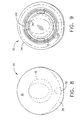
- Figures 8 and 9 are enlarged views of the distal and proximal ends, respectively, of the optical tip 30 shown in Figures 5, 6, and 7.
- Figure 8 illustrates how upper surface 31 is blended into lower surface 35 in this embodiment.
- Figure 9 shows how distal end 22 of shaft 20 is attached to ribs 36 of optical tip 30, providing radial clearance for the slidable insertion of endoscope 6.
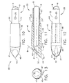
- Figures 10, 11, 12, and 13 are orthographic views of the distal portion of a second embodiment of the present invention.
- the second embodiment varies from the first embodiment shown in Figures 5, 6, and 7 in that an optical tip 40 of the second embodiment has a different shape than optical tip 30 of the first embodiment.
- Optical tip 40 comprises a cylindrical portion 48, a tapered portion 49, a proximal end 44 for attachment to shaft 20, and an apex 42 offset from longitudinal axis 50.
- Optical tip 40 further comprises a flat, upper surface 41 blended with a lower surface 45.
- Endoscope 6 having 30-degree tip 8 (also referred to as a distal viewing tip) is shown slidably inserted into a optical tip chamber 43.
- Purge ports 25 are shown in shaft 20 proximal to optical tip 40.
- Optical tip 40 further comprises a pair of dissecting blades 47 molded onto or separately attached to tapered portion 49. Blades 47 are on opposite sides of tapered portion 49 and extend from apex 42 in approximately the proximal longitudinal direction. Blades 47 are provided to assist in separating tissue layers, but are not sharp enough to cut tissue.
- the optical dissector 10, also referred to as an surgical instrument, of the present invention may be used in a wide variety of procedures requiring an initial penetration of tissue for creating a body cavity.
- One possible procedure is for harvesting a vessel, such as the saphenous vein, from a patient so that the vessel may be used later as a coronary artery bypass graft on that patient.
- the optical dissector 10 may be used for such a procedure in combination with the optical dissector/retractor having a transparent, concave head (also referred to as the DuBois device) disclosed in U.S. Patent 5,902,315.
- a method for using optical dissector 10 to create body cavity 7 is described next while referring to Figures 1 and 15.
- the surgeon first identifies blood vessel 3, such as the saphenous vein, to be harvested.
- a marker pen may be used to trace the underlying location of blood vessel 3 on the skin of the patient.
- the surgeon then makes an incision 1 in the tissue near blood vessel 3 using a cutting tool such as a scalpel.
- the surgeon places optical dissector 10 through incision 1 and maneuvers optical tip 30 over blood vessel 3, initially separating blood vessel 3 from upper tissue layer 2.
- optical tip 30 is advanced carefully past side branch 5.
- Optical dissector 10 is advanced a short distance in the distal direction along blood vessel 3, and then retracted partially in the proximal direction, creating body cavity 7 alongside blood vessel 3.
- optical dissector 10 is then withdrawn through incision 1. The surgeon may then proceed with the vessel harvesting procedure using, for example, an optical retractor/dissector having a transparent concave head as disclosed in U.S. 5,902,315.
Landscapes
- Health & Medical Sciences (AREA)
- Surgery (AREA)
- Life Sciences & Earth Sciences (AREA)
- Medical Informatics (AREA)
- Nuclear Medicine, Radiotherapy & Molecular Imaging (AREA)
- Engineering & Computer Science (AREA)
- Biomedical Technology (AREA)
- Heart & Thoracic Surgery (AREA)
- Rheumatology (AREA)
- Molecular Biology (AREA)
- Animal Behavior & Ethology (AREA)
- General Health & Medical Sciences (AREA)
- Public Health (AREA)
- Veterinary Medicine (AREA)
- Surgical Instruments (AREA)
- Endoscopes (AREA)
Abstract
Description
Claims (10)
- A surgical instrument for optically penetrating bodily tissue to create an initial body cavity and comprising:a. an elongated, hollow shaft having a longitudinal axis, a proximal end, and a distal end, said hollow shaft having a lumen therethrough; andb. an optical penetrating tip having a cylindrical portion attached to said distal end of said hollow shaft and a tapered portion extending distally therefrom, said tapered portion having an apex spaced laterally apart from said longitudinal axis.
- The surgical instrument of Claim 1 further comprising a handle attached to said proximal end of said hollow shaft.
- The surgical instrument of Claim 1 wherein said tapered portion of said optical penetrating tip comprises an upper surface blended into a lower surface, and said upper surface is sloped with respect to said longitudinal axis of said hollow shaft, and said upper surface has an average inclination axis when viewed from the side, and said average inclination axis forms an inclination angle with said longitudinal axis of said hollow shaft of between 15 and 75 degrees.
- The surgical instrument of Claim 3 wherein said tapered portion of said optical penetrating tip comprises an upper surface blended into a lower surface, and said upper surface is sloped with respect to said longitudinal axis of said hollow shaft, and said upper surface has an average inclination axis when viewed from the side, and said average inclination axis forms an inclination angle with said longitudinal axis of said hollow shaft of about 45 degrees.
- The surgical instrument of Claim 4 wherein said upper and lower surfaces of said tapered portion of said optical penetrating tip are non-planar.
- The surgical instrument of Claim 1 wherein said optical penetrating tip further comprises a hollow enclosed optical tip chamber in communication with said lumen of said hollow shaft for slidably inserting a distal viewing tip of an endoscope therein.
- The surgical instrument of Claim 1 wherein said optical penetrating tip is made from an optically transparent polymeric material and said tapered portion has a substantially uniform wall thickness.
- The surgical instrument of Claim 1 further comprising an endoscope slidably inserted into said lumen of said hollow shaft and positioned such that said endoscope has a tip having a field of view through said optical penetrating tip, said field of view having a central viewing axis therethrough, said central viewing axis making a viewing angle with respect to said longitudinal axis of at least about thirty degrees and said central viewing axis is closely aligned with said apex.
- The surgical instrument of Claim 1 further comprising at least one purge port in said distal end of said hollow shaft fluidly connected to a flow source, whereby particulate matter and moisture is purged from a body cavity created by said optical penetrating tip while said surgical instrument is inserted in said body cavity.
- The surgical instrument of claim 8, wherein said flow source comprises carbon dioxide gas.
Applications Claiming Priority (2)
| Application Number | Priority Date | Filing Date | Title |
|---|---|---|---|
| US09/365,946 US6206823B1 (en) | 1999-08-02 | 1999-08-02 | Surgical instrument and method for endoscopic tissue dissection |
| US365946 | 1999-08-02 |
Publications (3)
| Publication Number | Publication Date |
|---|---|
| EP1074224A2 true EP1074224A2 (en) | 2001-02-07 |
| EP1074224A3 EP1074224A3 (en) | 2001-04-04 |
| EP1074224B1 EP1074224B1 (en) | 2007-03-28 |
Family
ID=23441052
Family Applications (1)
| Application Number | Title | Priority Date | Filing Date |
|---|---|---|---|
| EP00306566A Expired - Lifetime EP1074224B1 (en) | 1999-08-02 | 2000-08-02 | Surgical instrument and method for endoscopic tissue dissection |
Country Status (6)
| Country | Link |
|---|---|
| US (1) | US6206823B1 (en) |
| EP (1) | EP1074224B1 (en) |
| JP (1) | JP4141624B2 (en) |
| AU (1) | AU774406B2 (en) |
| CA (1) | CA2314785C (en) |
| DE (1) | DE60034091T2 (en) |
Cited By (20)
| Publication number | Priority date | Publication date | Assignee | Title |
|---|---|---|---|---|
| EP1435843A4 (en) * | 2001-09-28 | 2006-12-13 | Ethicon Inc | Vessel harvesting retractor with dissection element |
| EP2545865A3 (en) * | 2003-10-03 | 2013-04-24 | Applied Medical Resources Corporation | Bladeless optical obturator |
| US20160000462A1 (en) * | 2013-02-11 | 2016-01-07 | Pajunk GmbH Medizintechnologie | Trocar |
| US10022150B2 (en) | 2008-09-29 | 2018-07-17 | Applied Medical Resources Corporation | First-entry trocar system |
| WO2019018470A1 (en) | 2017-07-18 | 2019-01-24 | Obp Medical Corporation | Minimally invasive no touch (mint) procedure for harvesting the great saphenous vein (gsv) and venous hydrodissector and retractor for use during the mint procedure |
| US10226589B2 (en) | 2003-10-03 | 2019-03-12 | Applied Medical Resources Corporation | Insufflating optical surgical instrument |
| US10368906B2 (en) | 2002-05-16 | 2019-08-06 | Applied Medical Resources Corporation | Blunt tip obturator |
| US10939899B2 (en) | 2015-06-03 | 2021-03-09 | Obp Medical Corporation | End cap assembly for retractor and other medical devices |
| US10952712B2 (en) | 2015-06-03 | 2021-03-23 | Obp Medical Corporation | Retractor |
| US10959609B1 (en) | 2020-01-31 | 2021-03-30 | Obp Medical Corporation | Illuminated suction device |
| US10966702B1 (en) | 2020-02-25 | 2021-04-06 | Obp Medical Corporation | Illuminated dual-blade retractor |
| US10966699B2 (en) | 2015-06-03 | 2021-04-06 | Obp Medical Corporation | Retractor |
| US11123105B2 (en) | 2006-10-06 | 2021-09-21 | Applied Medical Resources Corporation | Visual insufflation port |
| US11197662B2 (en) | 2015-02-05 | 2021-12-14 | Obp Surgical Corporation | Illuminated surgical retractor |
| US11253145B2 (en) | 2017-10-19 | 2022-02-22 | Obp Medical Corporation | Speculum |
| US11439379B2 (en) | 2015-02-05 | 2022-09-13 | Obp Surgical Corporation | Illuminated surgical retractor |
| US11717374B2 (en) | 2016-07-11 | 2023-08-08 | Obp Surgical Corporation | Illuminated suction device |
| US11744454B2 (en) | 2010-09-28 | 2023-09-05 | Obp Medical Corporation | Speculum |
| US11744568B2 (en) | 2018-02-20 | 2023-09-05 | Obp Surgical Corporation | Illuminated medical devices |
| US12318080B2 (en) | 2023-07-21 | 2025-06-03 | Coopersurgical, Inc. | Illuminated surgical retractor capable of hand-held operation and of being mounted to a fixed frame |
Families Citing this family (100)
| Publication number | Priority date | Publication date | Assignee | Title |
|---|---|---|---|---|
| US6436116B1 (en) * | 1997-10-06 | 2002-08-20 | Smith & Nephew, Inc. | Methods and apparatus for removing veins |
| DE19827360C2 (en) * | 1998-06-19 | 2000-05-31 | Storz Karl Gmbh & Co Kg | Medical instrument for endoscopic removal of the saphenous vein |
| US6648815B2 (en) | 1998-06-19 | 2003-11-18 | Karl Storz Gmbh & Co. Kg | Medical instrument and method for endoscopic removal of the saphenous vein |
| US6447443B1 (en) | 2001-01-13 | 2002-09-10 | Medtronic, Inc. | Method for organ positioning and stabilization |
| US7628780B2 (en) | 2001-01-13 | 2009-12-08 | Medtronic, Inc. | Devices and methods for interstitial injection of biologic agents into tissue |
| US7740623B2 (en) | 2001-01-13 | 2010-06-22 | Medtronic, Inc. | Devices and methods for interstitial injection of biologic agents into tissue |
| US20040138621A1 (en) * | 2003-01-14 | 2004-07-15 | Jahns Scott E. | Devices and methods for interstitial injection of biologic agents into tissue |
| EP1399071B1 (en) | 2001-06-26 | 2010-06-16 | Tyco Healthcare Group Lp | Blood vessel harvesting instrument |
| WO2003002022A2 (en) * | 2001-06-27 | 2003-01-09 | Depuy Products, Inc. | Minimally invasive orthopaedic apparatus and methods |
| EP2428171B1 (en) | 2001-09-24 | 2014-02-19 | Applied Medical Resources Corporation | Bladeless Obturator |
| US7967816B2 (en) | 2002-01-25 | 2011-06-28 | Medtronic, Inc. | Fluid-assisted electrosurgical instrument with shapeable electrode |
| US6660016B2 (en) | 2002-03-19 | 2003-12-09 | Terumo Corporation | Integrated vein dissector and cauterizing apparatus for endoscopic harvesting of blood vessels |
| US20040215057A1 (en) * | 2002-09-27 | 2004-10-28 | Wellman Parris S. | Portable, reusable visualization system |
| US20040093000A1 (en) * | 2002-10-23 | 2004-05-13 | Stephen Kerr | Direct vision port site dissector |
| US7056329B2 (en) * | 2002-10-23 | 2006-06-06 | Intellimed Surgical Solutions, Llc | Laparoscopic direct vision dissecting port |
| US6908427B2 (en) | 2002-12-30 | 2005-06-21 | PARÉ Surgical, Inc. | Flexible endoscope capsule |
| US7854724B2 (en) | 2003-04-08 | 2010-12-21 | Surgiquest, Inc. | Trocar assembly with pneumatic sealing |
| US8714429B2 (en) * | 2003-04-29 | 2014-05-06 | Covidien Lp | Dissecting tip for surgical stapler |
| US7138316B2 (en) * | 2003-09-23 | 2006-11-21 | Intel Corporation | Semiconductor channel on insulator structure |
| US20050096670A1 (en) * | 2003-10-31 | 2005-05-05 | Parris Wellman | Surgical end effector |
| US20050149094A1 (en) * | 2003-10-31 | 2005-07-07 | Olympus Corporation | Trocar |
| US20060173474A1 (en) * | 2003-10-31 | 2006-08-03 | Parris Wellman | Surgical device having a track to guide an actuator |
| US8105231B2 (en) * | 2003-10-31 | 2012-01-31 | Olympus Corporation | Living-body tissue removing apparatus |
| US7662164B2 (en) * | 2003-10-31 | 2010-02-16 | Olympus Corporation | Living-body tissue removing apparatus |
| US20050096645A1 (en) * | 2003-10-31 | 2005-05-05 | Parris Wellman | Multitool surgical device |
| US7314479B2 (en) | 2003-10-31 | 2008-01-01 | Parris Wellman | Space-creating retractor with vessel manipulator |
| US20050096646A1 (en) * | 2003-10-31 | 2005-05-05 | Parris Wellman | Surgical system for retracting and severing tissue |
| US20050096671A1 (en) * | 2003-10-31 | 2005-05-05 | Parris Wellman | Control mechanism for a surgical instrument |
| US7556633B2 (en) * | 2004-03-01 | 2009-07-07 | Terumo Corporation | Method and apparatus for endoscopic dissection of blood vessels |
| US20050203561A1 (en) * | 2004-03-09 | 2005-09-15 | Palmer Joetta R. | Lighted dissector and method for use |
| US20050203562A1 (en) * | 2004-03-09 | 2005-09-15 | Palmer Joetta R. | Lighted dissector and method for use |
| EP2263556A1 (en) * | 2004-05-13 | 2010-12-22 | Medtronic, Inc. | Percutaneous vein harvester |
| EP1750608B1 (en) | 2004-06-02 | 2012-10-03 | Medtronic, Inc. | Ablation device with jaws |
| EP1768573A2 (en) * | 2004-06-16 | 2007-04-04 | Medtronic, Inc. | Minimally invasive coring vein harvester |
| US7762951B2 (en) * | 2004-06-25 | 2010-07-27 | Medtronic, Inc. | Vein harvesting system including dilator shaft and removable retractor housing |
| US20060036274A1 (en) * | 2004-06-25 | 2006-02-16 | Usher Raymond W | One-piece vessel harvester |
| AU2011221382B2 (en) * | 2004-06-29 | 2013-08-22 | Applied Medical Resources Corporation | Insufflating optical surgical instrument |
| EP1815807B1 (en) * | 2004-09-22 | 2017-11-22 | Olympus Corporation | Organic tissue sampling device |
| EP1810621B1 (en) * | 2004-11-11 | 2019-07-03 | Olympus Corporation | An apparatus for treating a blood vessel in a living-body tissue |
| US8070767B2 (en) | 2005-01-28 | 2011-12-06 | Tyco Healthcare Group Lp | Optical penetrating adapter for surgical portal |
| US7470230B2 (en) * | 2005-03-31 | 2008-12-30 | Tyco Healthcare Group Lp | Optical obturator |
| US7824327B2 (en) * | 2005-04-12 | 2010-11-02 | Tyco Healthcare Group Llp | Optical trocar with scope holding assembly |
| US7951077B2 (en) * | 2005-07-15 | 2011-05-31 | Sayeg Ayoub Dr | Method and instruments for breast augmentation mammaplasty |
| US7367983B2 (en) | 2005-09-15 | 2008-05-06 | Dziadik Stephen P | Vessel harvesting apparatus |
| USD622380S1 (en) * | 2006-03-10 | 2010-08-24 | Medical Device Innovations Limited | Surgical instrument |
| USD623739S1 (en) * | 2006-03-10 | 2010-09-14 | Medical Device Innovations Limited | Surgical instrument handle |
| US9770230B2 (en) * | 2006-06-01 | 2017-09-26 | Maquet Cardiovascular Llc | Endoscopic vessel harvesting system components |
| US7806870B2 (en) * | 2006-10-06 | 2010-10-05 | Surgiquest, Incorporated | Elastically deformable surgical access device having telescoping guide tube |
| US7798998B2 (en) | 2006-10-06 | 2010-09-21 | Surgiquest, Inc. | Elastically deformable surgical access device |
| US8795235B2 (en) * | 2006-10-06 | 2014-08-05 | Surgiquest, Inc. | Devices for and methods of performing minimally-invasive surgical procedures through a single incision |
| EP2068732B1 (en) * | 2006-10-06 | 2014-04-23 | SurgiQuest, Incorporated | Visualization trocar |
| US20080161843A1 (en) * | 2006-10-16 | 2008-07-03 | Clague Cynthia T | Vessel support device and method of vessel harvesting |
| KR100828135B1 (en) * | 2006-12-13 | 2008-05-08 | 이은규 | Biotissue exfoliator for endoscope |
| EP2142116A4 (en) * | 2007-04-17 | 2013-07-17 | Covidien Lp | VISUAL SHUTTER WITH HANDLE |
| US8631991B2 (en) * | 2007-05-30 | 2014-01-21 | Ethicon Endo-Surgery, Inc. | Surgical instrument |
| AU2008202266B2 (en) * | 2007-06-01 | 2013-09-12 | Covidien Lp | Obturator tips |
| US8623046B2 (en) * | 2007-08-10 | 2014-01-07 | Donald Lee Sturtevant | Treatment for patients after removal of saphenous vascular material |
| US8192353B2 (en) * | 2007-10-05 | 2012-06-05 | Tyco Healthcare Group Lp | Visual obturator |
| USD667954S1 (en) | 2007-10-05 | 2012-09-25 | Surgiquest, Inc. | Visualization trocar |
| USD663838S1 (en) | 2007-10-05 | 2012-07-17 | Surgiquest, Inc. | Visualization trocar |
| US9402643B2 (en) | 2008-01-15 | 2016-08-02 | Novartis Ag | Targeted illumination for surgical instrument |
| ES2651687T3 (en) | 2008-03-31 | 2018-01-29 | Applied Medical Resources Corporation | Electrosurgical system with a memory module |
| EP2341849B1 (en) | 2008-10-10 | 2019-12-18 | SurgiQuest, Incorporated | System for improved gas recirculation in surgical trocars with pneumatic sealing |
| WO2010124129A1 (en) * | 2009-04-22 | 2010-10-28 | Pare Surgical, Inc. | Endoscopic tissue grasping apparatus and method |
| US9226774B2 (en) | 2009-12-17 | 2016-01-05 | Covidien Lp | Visual obturator with tip openings |
| US8979883B2 (en) | 2009-12-17 | 2015-03-17 | Covidien Lp | Obturator tip |
| US8220688B2 (en) * | 2009-12-24 | 2012-07-17 | Ethicon Endo-Surgery, Inc. | Motor-driven surgical cutting instrument with electric actuator directional control assembly |
| US20110172688A1 (en) * | 2010-01-11 | 2011-07-14 | Tyco Healthcare Group Lp | Conduit Harvesting Instrument and Method |
| US9144455B2 (en) | 2010-06-07 | 2015-09-29 | Just Right Surgical, Llc | Low power tissue sealing device and method |
| US20120035425A1 (en) | 2010-08-09 | 2012-02-09 | Philipp Schaller | Illuminated Surgical Instrument |
| USD654168S1 (en) | 2010-09-21 | 2012-02-14 | Tyco Healthcare Group Lp | Bladeless obturator member |
| USD655005S1 (en) | 2010-09-21 | 2012-02-28 | Tyco Healthcare Group Lp | Bladeless obturator member |
| USD656233S1 (en) | 2010-09-21 | 2012-03-20 | Tyco Healthcare Group Lp | Bladeless obturator member |
| EP2621389B1 (en) | 2010-10-01 | 2015-03-18 | Applied Medical Resources Corporation | Electrosurgical instrument with jaws and with an electrode |
| US9039694B2 (en) | 2010-10-22 | 2015-05-26 | Just Right Surgical, Llc | RF generator system for surgical vessel sealing |
| US8771173B2 (en) * | 2010-12-14 | 2014-07-08 | Saint Joseph's Translational Research Institute, Inc. | Access device for surgery |
| WO2012122263A2 (en) | 2011-03-08 | 2012-09-13 | Surgiquest, Inc. | Trocar assembly with pneumatic sealing |
| US9204939B2 (en) * | 2011-08-21 | 2015-12-08 | M.S.T. Medical Surgery Technologies Ltd. | Device and method for assisting laparoscopic surgery—rule based approach |
| DE102011056705A1 (en) * | 2011-12-20 | 2013-06-20 | Aesculap Ag | Medical obturator and trocar |
| US20140275768A1 (en) * | 2013-03-13 | 2014-09-18 | Covidien Lp | Thoracic Scope With Skirt And Gap |
| US10561302B2 (en) * | 2013-03-15 | 2020-02-18 | DePuy Synthes Products, Inc. | Viewing trocar with integrated prism for use with angled endoscope |
| US9642642B2 (en) * | 2013-09-20 | 2017-05-09 | Kok Hoo LIM | Guide tip introducer and method to create thereof |
| EP4649907A3 (en) | 2014-05-16 | 2026-02-25 | Applied Medical Resources Corporation | Electrosurgical system |
| KR102420273B1 (en) | 2014-05-30 | 2022-07-13 | 어플라이드 메디컬 리소시스 코포레이션 | Electrosurgical instrument for fusing and cutting tissue and an electrosurgical generator |
| US10575835B2 (en) | 2014-10-14 | 2020-03-03 | Covidien Lp | Methods and devices for vein harvesting |
| US10646210B2 (en) | 2014-10-14 | 2020-05-12 | Covidien Lp | Methods and devices for vein harvesting |
| AU2015369954B2 (en) | 2014-12-23 | 2020-07-23 | Appplied Medical Resources Corporation | Bipolar electrosurgical sealer and divider |
| USD748259S1 (en) | 2014-12-29 | 2016-01-26 | Applied Medical Resources Corporation | Electrosurgical instrument |
| US10244931B2 (en) | 2015-07-13 | 2019-04-02 | Novartis Ag | Illuminated ophthalmic infusion line and associated devices, systems, and methods |
| US10064611B2 (en) | 2015-07-22 | 2018-09-04 | Covidien Lp | Methods and devices for vein harvesting |
| US10117675B2 (en) * | 2015-07-28 | 2018-11-06 | Covidien Lp | Trocar tip protector |
| US11173008B2 (en) | 2015-11-01 | 2021-11-16 | Alcon Inc. | Illuminated ophthalmic cannula |
| US9956053B2 (en) | 2016-03-04 | 2018-05-01 | Novartis Ag | Cannula with an integrated illumination feature |
| US10765471B2 (en) | 2016-04-15 | 2020-09-08 | Bolder Surgical, Llc | Electrosurgical sealer and divider |
| US11547466B2 (en) | 2018-06-20 | 2023-01-10 | Covidien Lp | Visualization devices and methods for use in surgical procedures |
| US10786252B2 (en) * | 2018-07-16 | 2020-09-29 | Ethicon Llc | Surgical stapling end effector component with deformable tip having void |
| KR20210055073A (en) | 2018-09-05 | 2021-05-14 | 어플라이드 메디컬 리소시스 코포레이션 | Generator control system for electrosurgery |
| USD904611S1 (en) | 2018-10-10 | 2020-12-08 | Bolder Surgical, Llc | Jaw design for a surgical instrument |
| WO2020101954A1 (en) | 2018-11-16 | 2020-05-22 | Applied Medical Resources Corporation | Electrosurgical system |
| EP4110203B1 (en) | 2020-03-10 | 2025-05-07 | Children's Medical Center Corporation | Minimally invasive dissector for inter-layer procedures |
Family Cites Families (21)
| Publication number | Priority date | Publication date | Assignee | Title |
|---|---|---|---|---|
| NL250623A (en) * | 1959-05-05 | |||
| US3297022A (en) * | 1963-09-27 | 1967-01-10 | American Cystoscope Makers Inc | Endoscope |
| US4132227A (en) * | 1974-08-08 | 1979-01-02 | Winter & Ibe | Urological endoscope particularly resectoscope |
| US5514153A (en) | 1990-03-02 | 1996-05-07 | General Surgical Innovations, Inc. | Method of dissecting tissue layers |
| US5685820A (en) | 1990-11-06 | 1997-11-11 | Partomed Medizintechnik Gmbh | Instrument for the penetration of body tissue |
| DE4035146A1 (en) | 1990-11-06 | 1992-05-07 | Riek Siegfried | INSTRUMENT FOR PENETRATING BODY TISSUE |
| US5373840A (en) | 1992-10-02 | 1994-12-20 | Knighton; David R. | Endoscope and method for vein removal |
| US5385572A (en) | 1992-11-12 | 1995-01-31 | Beowulf Holdings | Trocar for endoscopic surgery |
| US5334150A (en) | 1992-11-17 | 1994-08-02 | Kaali Steven G | Visually directed trocar for laparoscopic surgical procedures and method of using same |
| US5441041A (en) | 1993-09-13 | 1995-08-15 | United States Surgical Corporation | Optical trocar |
| US5573493A (en) * | 1993-10-08 | 1996-11-12 | United States Surgical Corporation | Endoscope attachment for changing angle of view |
| US5720761A (en) | 1993-11-16 | 1998-02-24 | Worldwide Optical Trocar Licensing Corp. | Visually directed trocar and method |
| US5609562A (en) | 1993-11-16 | 1997-03-11 | Worldwide Optical Trocar Licensing Corporation | Visually directed trocar and method |
| US5448990A (en) * | 1994-02-15 | 1995-09-12 | Very Inventive Physicians, Inc. | Endoscope viewing cannula and surgical techniques |
| JP3379821B2 (en) | 1994-05-31 | 2003-02-24 | オリンパス光学工業株式会社 | Endoscope |
| US5569291A (en) | 1995-02-01 | 1996-10-29 | Ethicon Endo-Surgery, Inc. | Surgical penetration and dissection instrument |
| US5759150A (en) * | 1995-07-07 | 1998-06-02 | Olympus Optical Co., Ltd. | System for evulsing subcutaneous tissue |
| US5667480A (en) | 1995-10-20 | 1997-09-16 | Ethicon Endo-Surgery, Inc. | Method and devices for endoscopic vessel harvesting |
| US5928138A (en) * | 1996-08-15 | 1999-07-27 | Ethicon Endo-Surgery, Inc. | Method and devices for endoscopic vessel harvesting |
| US5836945A (en) | 1997-02-20 | 1998-11-17 | Perkins; Rodney C. | Biological vessel harvesting device |
| US5902315A (en) | 1997-08-28 | 1999-05-11 | Ethicon Endo-Surgery, Inc. | Optical tissue dissector/retractor |
-
1999
- 1999-08-02 US US09/365,946 patent/US6206823B1/en not_active Expired - Fee Related
-
2000
- 2000-08-01 CA CA002314785A patent/CA2314785C/en not_active Expired - Fee Related
- 2000-08-02 JP JP2000234840A patent/JP4141624B2/en not_active Expired - Fee Related
- 2000-08-02 EP EP00306566A patent/EP1074224B1/en not_active Expired - Lifetime
- 2000-08-02 DE DE60034091T patent/DE60034091T2/en not_active Expired - Fee Related
- 2000-08-08 AU AU51898/00A patent/AU774406B2/en not_active Ceased
Cited By (40)
| Publication number | Priority date | Publication date | Assignee | Title |
|---|---|---|---|---|
| US10568658B2 (en) | 2001-09-24 | 2020-02-25 | Applied Medical Resources Corporation | Bladeless optical obturator |
| US9655643B2 (en) | 2001-09-24 | 2017-05-23 | Applied Medical Resources Corporation | Bladeless optical obturator |
| EP1435843A4 (en) * | 2001-09-28 | 2006-12-13 | Ethicon Inc | Vessel harvesting retractor with dissection element |
| US11207098B2 (en) | 2002-05-16 | 2021-12-28 | Applied Medical Resources Corporation | Blunt tip obturator |
| US10368906B2 (en) | 2002-05-16 | 2019-08-06 | Applied Medical Resources Corporation | Blunt tip obturator |
| EP2545865A3 (en) * | 2003-10-03 | 2013-04-24 | Applied Medical Resources Corporation | Bladeless optical obturator |
| EP2921121A1 (en) * | 2003-10-03 | 2015-09-23 | Applied Medical Resources Corporation | Bladeless optical obturator |
| US10918814B2 (en) | 2003-10-03 | 2021-02-16 | Applied Medical Resources Corporation | Insufflating optical surgical instrument |
| US10226589B2 (en) | 2003-10-03 | 2019-03-12 | Applied Medical Resources Corporation | Insufflating optical surgical instrument |
| US11123105B2 (en) | 2006-10-06 | 2021-09-21 | Applied Medical Resources Corporation | Visual insufflation port |
| US10856906B2 (en) | 2008-09-29 | 2020-12-08 | Applied Medical Resources Corporation | First-entry trocar system |
| US10022150B2 (en) | 2008-09-29 | 2018-07-17 | Applied Medical Resources Corporation | First-entry trocar system |
| US11723689B2 (en) | 2008-09-29 | 2023-08-15 | Applied Medical Resources Corporation | First-entry trocar system |
| US11744454B2 (en) | 2010-09-28 | 2023-09-05 | Obp Medical Corporation | Speculum |
| US20160000462A1 (en) * | 2013-02-11 | 2016-01-07 | Pajunk GmbH Medizintechnologie | Trocar |
| US11197662B2 (en) | 2015-02-05 | 2021-12-14 | Obp Surgical Corporation | Illuminated surgical retractor |
| US12089829B2 (en) | 2015-02-05 | 2024-09-17 | Obp Surgical Corporation | Illuminated surgical retractor |
| US12329370B2 (en) | 2015-02-05 | 2025-06-17 | Coopersurgical, Inc. | Illuminated surgical retractor |
| US11439379B2 (en) | 2015-02-05 | 2022-09-13 | Obp Surgical Corporation | Illuminated surgical retractor |
| US10966699B2 (en) | 2015-06-03 | 2021-04-06 | Obp Medical Corporation | Retractor |
| US11622756B2 (en) | 2015-06-03 | 2023-04-11 | Obp Surgical Corporation | End cap assembly for retractor and other medical devices |
| US12201287B2 (en) | 2015-06-03 | 2025-01-21 | Coopersurgical, Inc. | Retractor |
| US10952712B2 (en) | 2015-06-03 | 2021-03-23 | Obp Medical Corporation | Retractor |
| US10939899B2 (en) | 2015-06-03 | 2021-03-09 | Obp Medical Corporation | End cap assembly for retractor and other medical devices |
| US11717374B2 (en) | 2016-07-11 | 2023-08-08 | Obp Surgical Corporation | Illuminated suction device |
| EP3654859A4 (en) * | 2017-07-18 | 2020-12-02 | Obp Medical Corporation | MINIMALLY INVASIVE CONTACTLESS (MINT) PROCEDURE FOR EXTRACTION OF THE VENA SAPHENA MAGNA (VSM) AND VENOUS HYDRODISSECTOR AND RETRACTOR FOR USE DURING THE MINT PROCEDURE |
| US11540817B2 (en) | 2017-07-18 | 2023-01-03 | Obp Surgical Corporation | Minimally invasive no touch (MINT) procedure for harvesting the great saphenous vein (GSV) and venous hydrodissector and retractor for use during the mint procedure |
| WO2019018470A1 (en) | 2017-07-18 | 2019-01-24 | Obp Medical Corporation | Minimally invasive no touch (mint) procedure for harvesting the great saphenous vein (gsv) and venous hydrodissector and retractor for use during the mint procedure |
| US11253145B2 (en) | 2017-10-19 | 2022-02-22 | Obp Medical Corporation | Speculum |
| US12383129B2 (en) | 2017-10-19 | 2025-08-12 | Coopersurgical, Inc. | Medical devices with battery removal |
| US11744568B2 (en) | 2018-02-20 | 2023-09-05 | Obp Surgical Corporation | Illuminated medical devices |
| US12502165B2 (en) | 2018-02-20 | 2025-12-23 | Coopersurgical, Inc. | Illuminated medical devices |
| US12599376B2 (en) | 2018-02-20 | 2026-04-14 | Coopersurgical, Inc. | Illuminated medical devices |
| US10959609B1 (en) | 2020-01-31 | 2021-03-30 | Obp Medical Corporation | Illuminated suction device |
| US12246124B2 (en) | 2020-01-31 | 2025-03-11 | Coopersurgical, Inc. | Illuminated suction device |
| US11617822B2 (en) | 2020-01-31 | 2023-04-04 | Obp Surgical Corporation | Illuminated suction device |
| US11622758B2 (en) | 2020-02-25 | 2023-04-11 | Obp Surgical Corporation | Illuminated dual-blade retractor |
| US10966702B1 (en) | 2020-02-25 | 2021-04-06 | Obp Medical Corporation | Illuminated dual-blade retractor |
| US12544055B2 (en) | 2020-02-25 | 2026-02-10 | Coopersurgical, Inc. | Illuminated dual-blade retractor |
| US12318080B2 (en) | 2023-07-21 | 2025-06-03 | Coopersurgical, Inc. | Illuminated surgical retractor capable of hand-held operation and of being mounted to a fixed frame |
Also Published As
| Publication number | Publication date |
|---|---|
| EP1074224B1 (en) | 2007-03-28 |
| EP1074224A3 (en) | 2001-04-04 |
| AU774406B2 (en) | 2004-06-24 |
| CA2314785A1 (en) | 2001-02-02 |
| JP4141624B2 (en) | 2008-08-27 |
| JP2001079010A (en) | 2001-03-27 |
| DE60034091D1 (en) | 2007-05-10 |
| US6206823B1 (en) | 2001-03-27 |
| AU5189800A (en) | 2001-02-08 |
| CA2314785C (en) | 2007-04-10 |
| DE60034091T2 (en) | 2008-01-24 |
Similar Documents
| Publication | Publication Date | Title |
|---|---|---|
| US6206823B1 (en) | Surgical instrument and method for endoscopic tissue dissection | |
| US5667480A (en) | Method and devices for endoscopic vessel harvesting | |
| EP0904736B1 (en) | Improved endoscopic tissue dissector/retractor | |
| US5922004A (en) | Method for performing optical tissue dissection/retraction | |
| US5928135A (en) | Method and devices for endoscopic vessel harvesting | |
| US5980549A (en) | Tissue separation cannula with dissection probe and method | |
| US6951568B1 (en) | Low-profile multi-function vessel harvester and method | |
| US5873889A (en) | Tissue separation cannula with dissection probe and method | |
| US7384423B1 (en) | Tissue dissection method | |
| US6042538A (en) | Device for endoscopic vessel harvesting | |
| AU719712B2 (en) | Tissue separation cannula with dissection probe and method | |
| US7510562B2 (en) | Vein dissector, cauterizing and ligating apparatus for endoscopic harvesting of blood vessels | |
| JPH09122133A5 (en) | ||
| EP1810621B1 (en) | An apparatus for treating a blood vessel in a living-body tissue | |
| WO1999025238A2 (en) | Device for endoscopic vessel harvesting | |
| CA2537342C (en) | Method and devices for endoscopic vessel harvesting |
Legal Events
| Date | Code | Title | Description |
|---|---|---|---|
| PUAI | Public reference made under article 153(3) epc to a published international application that has entered the european phase |
Free format text: ORIGINAL CODE: 0009012 |
|
| AK | Designated contracting states |
Kind code of ref document: A2 Designated state(s): DE ES FR GB IT NL |
|
| AX | Request for extension of the european patent |
Free format text: AL;LT;LV;MK;RO;SI |
|
| PUAL | Search report despatched |
Free format text: ORIGINAL CODE: 0009013 |
|
| AK | Designated contracting states |
Kind code of ref document: A3 Designated state(s): AT BE CH CY DE DK ES FI FR GB GR IE IT LI LU MC NL PT SE |
|
| AX | Request for extension of the european patent |
Free format text: AL;LT;LV;MK;RO;SI |
|
| RIC1 | Information provided on ipc code assigned before grant |
Free format text: 7A 61B 17/00 A, 7A 61B 17/34 B |
|
| 17P | Request for examination filed |
Effective date: 20010914 |
|
| AKX | Designation fees paid |
Free format text: DE ES FR GB IT NL |
|
| 17Q | First examination report despatched |
Effective date: 20050207 |
|
| GRAP | Despatch of communication of intention to grant a patent |
Free format text: ORIGINAL CODE: EPIDOSNIGR1 |
|
| GRAS | Grant fee paid |
Free format text: ORIGINAL CODE: EPIDOSNIGR3 |
|
| GRAA | (expected) grant |
Free format text: ORIGINAL CODE: 0009210 |
|
| AK | Designated contracting states |
Kind code of ref document: B1 Designated state(s): DE ES FR GB IT NL |
|
| REG | Reference to a national code |
Ref country code: GB Ref legal event code: FG4D |
|
| RAP2 | Party data changed (patent owner data changed or rights of a patent transferred) |
Owner name: DATASCOPE CORP. |
|
| REF | Corresponds to: |
Ref document number: 60034091 Country of ref document: DE Date of ref document: 20070510 Kind code of ref document: P |
|
| NLT2 | Nl: modifications (of names), taken from the european patent patent bulletin |
Owner name: DATASCOPE CORP. Effective date: 20070502 |
|
| PG25 | Lapsed in a contracting state [announced via postgrant information from national office to epo] |
Ref country code: ES Free format text: LAPSE BECAUSE OF FAILURE TO SUBMIT A TRANSLATION OF THE DESCRIPTION OR TO PAY THE FEE WITHIN THE PRESCRIBED TIME-LIMIT Effective date: 20070709 |
|
| ET | Fr: translation filed | ||
| REG | Reference to a national code |
Ref country code: FR Ref legal event code: TP |
|
| PLBE | No opposition filed within time limit |
Free format text: ORIGINAL CODE: 0009261 |
|
| STAA | Information on the status of an ep patent application or granted ep patent |
Free format text: STATUS: NO OPPOSITION FILED WITHIN TIME LIMIT |
|
| 26N | No opposition filed |
Effective date: 20080102 |
|
| PGFP | Annual fee paid to national office [announced via postgrant information from national office to epo] |
Ref country code: DE Payment date: 20080814 Year of fee payment: 9 Ref country code: NL Payment date: 20080803 Year of fee payment: 9 |
|
| PGFP | Annual fee paid to national office [announced via postgrant information from national office to epo] |
Ref country code: IT Payment date: 20080828 Year of fee payment: 9 Ref country code: FR Payment date: 20080818 Year of fee payment: 9 |
|
| PGFP | Annual fee paid to national office [announced via postgrant information from national office to epo] |
Ref country code: GB Payment date: 20080813 Year of fee payment: 9 |
|
| REG | Reference to a national code |
Ref country code: NL Ref legal event code: V1 Effective date: 20100301 |
|
| GBPC | Gb: european patent ceased through non-payment of renewal fee |
Effective date: 20090802 |
|
| REG | Reference to a national code |
Ref country code: FR Ref legal event code: ST Effective date: 20100430 |
|
| PG25 | Lapsed in a contracting state [announced via postgrant information from national office to epo] |
Ref country code: NL Free format text: LAPSE BECAUSE OF NON-PAYMENT OF DUE FEES Effective date: 20100301 Ref country code: DE Free format text: LAPSE BECAUSE OF NON-PAYMENT OF DUE FEES Effective date: 20100302 Ref country code: FR Free format text: LAPSE BECAUSE OF NON-PAYMENT OF DUE FEES Effective date: 20090831 |
|
| PG25 | Lapsed in a contracting state [announced via postgrant information from national office to epo] |
Ref country code: GB Free format text: LAPSE BECAUSE OF NON-PAYMENT OF DUE FEES Effective date: 20090802 |
|
| PG25 | Lapsed in a contracting state [announced via postgrant information from national office to epo] |
Ref country code: IT Free format text: LAPSE BECAUSE OF NON-PAYMENT OF DUE FEES Effective date: 20090802 |