EP1073157A1 - Adjustable cable egress mechanism for cable connectors - Google Patents
Adjustable cable egress mechanism for cable connectors Download PDFInfo
- Publication number
- EP1073157A1 EP1073157A1 EP00305861A EP00305861A EP1073157A1 EP 1073157 A1 EP1073157 A1 EP 1073157A1 EP 00305861 A EP00305861 A EP 00305861A EP 00305861 A EP00305861 A EP 00305861A EP 1073157 A1 EP1073157 A1 EP 1073157A1
- Authority
- EP
- European Patent Office
- Prior art keywords
- cable
- hub
- hood
- egress
- passage
- Prior art date
- Legal status (The legal status is an assumption and is not a legal conclusion. Google has not performed a legal analysis and makes no representation as to the accuracy of the status listed.)
- Granted
Links
- 239000004020 conductor Substances 0.000 claims abstract description 17
- 230000001681 protective effect Effects 0.000 claims abstract description 4
- 230000013011 mating Effects 0.000 claims description 8
- 230000000452 restraining effect Effects 0.000 claims 5
- 239000000835 fiber Substances 0.000 description 2
- 238000009434 installation Methods 0.000 description 2
- 239000000463 material Substances 0.000 description 2
- 239000004676 acrylonitrile butadiene styrene Substances 0.000 description 1
- 230000000712 assembly Effects 0.000 description 1
- 238000000429 assembly Methods 0.000 description 1
- 238000010292 electrical insulation Methods 0.000 description 1
- 239000000203 mixture Substances 0.000 description 1
- 238000012986 modification Methods 0.000 description 1
- 230000004048 modification Effects 0.000 description 1
- 239000013307 optical fiber Substances 0.000 description 1
- 239000004033 plastic Substances 0.000 description 1
- 229920003023 plastic Polymers 0.000 description 1
- 239000004417 polycarbonate Substances 0.000 description 1
- 229920000515 polycarbonate Polymers 0.000 description 1
- 230000002441 reversible effect Effects 0.000 description 1
Images



Classifications
-
- H—ELECTRICITY
- H01—ELECTRIC ELEMENTS
- H01R—ELECTRICALLY-CONDUCTIVE CONNECTIONS; STRUCTURAL ASSOCIATIONS OF A PLURALITY OF MUTUALLY-INSULATED ELECTRICAL CONNECTING ELEMENTS; COUPLING DEVICES; CURRENT COLLECTORS
- H01R13/00—Details of coupling devices of the kinds covered by groups H01R12/70 or H01R24/00 - H01R33/00
- H01R13/58—Means for relieving strain on wire connection, e.g. cord grip, for avoiding loosening of connections between wires and terminals within a coupling device terminating a cable
- H01R13/5841—Means for relieving strain on wire connection, e.g. cord grip, for avoiding loosening of connections between wires and terminals within a coupling device terminating a cable allowing different orientations of the cable with respect to the coupling direction
Definitions
- This invention relates generally to cable connectors for cables used in voice and data communication systems.
- U.S. Patent 3,794,960 issued Feb. 26, 1974 discloses an electrical connector junction shell that supports a cable which exits from the associated connector with an in-line or "straight up" configuration (i.e., at an angle of 180 degrees with respect to the face of the connector), or at a right angle (90 degrees) with respect to the connector face.
- in-line or "straight up" configuration i.e., at an angle of 180 degrees with respect to the face of the connector
- 90 degrees right angle
- U.S. Patent 4,761,145 issued Aug. 2, 1988 shows an electrical connector with a housing that has three openings facing in different directions through which wires can exit in a selected direction. To change the egress direction, it is necessary to disassemble the connector housing, redirect the wires through a different opening, and to clamp the wires with a clamp piece and an actuating screw.
- the known connector housings or shells do not permit wires or cables to be set conveniently at a desired egress angle to meet the needs of various installations where angles ranging from, for example, 110 to 240 degrees may be required.
- an adjustable cable egress mechanism for cable connectors includes a protective hood, and a supporting hub that is mounted within the hood for rotation about a hub axis.
- the hub has a cable passage
- the hood has an outside wall with a cable egress slot.
- the egress slot is formed in the hood to open into the cable passage in the hub, over a predetermined range of angular positions of the hub about the hub axis.
- a cable connector comprises a connector body having a terminal face for engaging terminals of a mating connector, and a cable end face for terminating cable conductors, diverging from a cable end of an outside cable.
- a hood is constructed and arranged for protectively enclosing the conductors and the cable in the region of the end face of the connector body, and a hub is mounted for rotation about a hub axis within the hood, the hub having a cable passage.
- the hood has a wall with a cable egress slot formed to open into the cable passage in the hub over a range of angular positions about the hub axis.
- a cable assembly includes a length of cable having a cable end, and a number of cable conductors diverging from the cable end.
- the assembly also includes a connector body having a terminal face, and a cable end face for terminating cable conductors from the cable end.
- a hood is constructed and arranged for protectively enclosing the conductors and the cable end near the end face of the connector body, and a hub is mounted within the hood for rotation about a hub axis, the hub having a cable passage.
- a wall of the hood has a cable egress slot formed to open into the cable passage in the hub over a certain range of angular positions about the hub axis, and the cable passes through the cable egress slot in the hood and extends in the cable passage in the hub, so that the cable may rotate with the hub about the hub axis and be supported by the hub at a desired egress angle within the mentioned range.
- FIG. 1 is a perspective view of a connector 10 with an adjustable cable egress mechanism 12 according to the invention.
- the connector 10 has a generally rectangular, elongated connector body 14.
- the connector body 14 has a terminal face 16 at a front side of the body for engaging terminals of a mating connector (not shown).
- the connector body may be, for example, that of a commercially available 25-pair cable plug connector meeting FCC rules, Part 68, Subpart F, for 50-pin miniature ribbon connectors.
- the invention is not limited with respect to a particular connector body, and may be applied in other types of electrical connectors as well as in connectors for optical fiber cables.
- cable conductors in the form of insulated wires may be terminated inside the connector body 14.
- the wires are individually routed or "dressed” over a cable end face 18 of the connector body 14, so that the wires diverge neatly and evenly from an end of a jacketed cable into the connector cable end face 18.
- the cable egress mechanism 12 comprises a hood or shell 30 for protectively enclosing individual wires dressed over the end face 18 of the connector body 14, as well as the end of the jacketed cable from which the wires diverge.
- Hood 30 may, for example, be molded from a plastics material meeting all applicable standards with respect to electrical insulation and flammability. Suitable materials include, e.g., polycarbonate, ABS, and blends thereof.
- a typical wall thickness of the hood 30 is about 0.050 inches.
- a front portion of the hood 30 has an opening with a cross section that conforms to the periphery of the cable end face 18 on the connector body 14.
- a pair of resilient loop snaps, 32, 34 project from both side ends of the front portion of the hood 30.
- the snaps 32, 34 have openings for engaging corresponding block protrusions 36, 38, at opposite side ends of the connector body 14.
- the hood 30 also has a pair of fastener openings 40, 42, formed in the vicinity of the loop snaps 32, 34.
- the openings 40, 42 permit a pair of connector screws 44, 46, to be inserted from outside the hood 30, and to pass through corresponding openings 48, 50, in opposite side ends of the connector body 14. Threaded ends of the connector screws 44, 46, may then engage corresponding threaded openings in the body of a mating connector, and both of the screws tightened from the cable end face side of the connector body 14 to fasten the connector 10 on the mating connector.
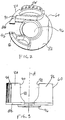
- FIGS. 2 and 3 show further details of the hub 60 in the cable egress mechanism 12.
- the hub 60 has a generally disk-shaped base 82, and two partial circumferential walls 84, 86.
- the two walls 84, 86, and the base 82 define a cable passage 88 through the hub 60. That is, the cable passage 88 lies above the hub base 82 and is substantially perpendicular to the hub axis A.
- a left end of the cable passage 88 is bordered by opposed, circumferentially spaced extensions 90, 92, from the hub walls 84, 86.
- Hub wall 84 also has a number of axially extending indexing grooves 94 in its circumference.
- Each of the grooves 94 is of such dimensions as to receive and to seat the pawl 70 at the free end of the indexing latch 66, when the hub 60 is rotated to align one of the grooves 94 with the latch pawl 70.
- seven equi-circumferentially spaced grooves 94 are formed in the circumference of the hub wall 84, so that the support hub 60 may be rotated to a selected one of seven angular positions when the hub is mounted within the connector hood 30, and the pawl 70 is seated in the corresponding groove in the hub wall.
- the cable end collar 98 is crimped about the cable jacket near the position where the jacket is removed, to allow the cable wires to diverge and terminate in the connector body 14.
- the egress mechanism 12 is then slid back down the cable, and the loop snaps 32, 34, on the hood 30 are snapped onto the protrusions 36, 38, on the connector body.
- a desired angle of cable egress may be set by urging the pawl 70 of the indexing latch 66 away from the hub 60, and rotating the cable to the desired position by as much as, for example, 30 degrees from horizontal.
- FIG. 5 shows cable egress at 110 degrees, i.e., 30 degrees above horizontal at the left side of FIG. 5.
- FIG. 6 shows a left-side egress at an angle of about 150 degrees, or 60 degrees above horizontal at the left side of the connector 10 in FIG. 6.
- FIG. 7 shows cable egress at 240 degrees, i.e., 30 degrees above horizontal at the right side of connector 10 in FIG. 7.
- the cable egress slot 74 in the hood 30 should face the desired direction of cable egress.
- the hood 30 is "reversible" as shown by FIGS. 5 and 7. That is, the cable egress mechanism 12 may be removed from the connector body 14 by unfastening the screws 44, 46, releasing the hood snaps 32, 34, flipping the hood 180 degrees about the cable axis, and re-fastening the hood to the connector body.
- This feature allows the cable egress slot 74 to extend along the hood in only one direction from the slot end 76 which corresponds to the 180 degree cable egress position in FIG. 4.
- a conventional releaseable friction clutch may be arranged between the hood 30 and the rotatable hub 60, to allow a cable terminated in the connector body 14 to be moved and set at a desired angle relative to the connector body.
Landscapes
- Details Of Connecting Devices For Male And Female Coupling (AREA)
- Electric Cable Arrangement Between Relatively Moving Parts (AREA)
Abstract

Description
- This invention relates generally to cable connectors for cables used in voice and data communication systems.
- Industry standard "Category 5" cables comprise 25 unshielded twisted pairs (UTP) of insulated wires for carrying voice and data signals. These cables are quite rigid and difficult to bend. Thus, it becomes difficult if not impossible for a customer always to be able to route such cables conveniently in various applications where space is limited. When a number of typical 25-wire pair connectors associated with such cables are mounted in close proximity to one another, as normally occurs in the field, the stiffness of the cables makes their routing near the connectors especially troublesome.
- In an attempt to meet different user applications, various connector arrangements have been proposed that offer the user a limited number of options with respect to cable egress angle relative to a connector body. This requires the user to determine beforehand which angle or angles are best suited for a particular application, however. Also, suppliers of such connectors must inventory a number of different cable connector/cable assemblies, so as to accommodate user requests for a particular plug connector type and cable length.
- U.S. Patent 3,794,960 issued Feb. 26, 1974, discloses an electrical connector junction shell that supports a cable which exits from the associated connector with an in-line or "straight up" configuration (i.e., at an angle of 180 degrees with respect to the face of the connector), or at a right angle (90 degrees) with respect to the connector face. As mentioned, applications exist where cable egress angles other than 180 or 90 degrees may be desirable to satisfy installations where a number of connectors are mounted close to one another and space for routing of the connector cables is limited.
- Further, U.S. Patent 4,761,145 issued Aug. 2, 1988, shows an electrical connector with a housing that has three openings facing in different directions through which wires can exit in a selected direction. To change the egress direction, it is necessary to disassemble the connector housing, redirect the wires through a different opening, and to clamp the wires with a clamp piece and an actuating screw.
- Accordingly, the known connector housings or shells do not permit wires or cables to be set conveniently at a desired egress angle to meet the needs of various installations where angles ranging from, for example, 110 to 240 degrees may be required.
- According to the invention, an adjustable cable egress mechanism for cable connectors includes a protective hood, and a supporting hub that is mounted within the hood for rotation about a hub axis. The hub has a cable passage, and the hood has an outside wall with a cable egress slot. The egress slot is formed in the hood to open into the cable passage in the hub, over a predetermined range of angular positions of the hub about the hub axis. Thus, an outside cable passing through the cable egress slot and extending in the cable passage in the hub can be rotated with the hub about the hub axis and supported by the hub at a desired egress angle within the predetermined range.
- According to another aspect of the invention, a cable connector comprises a connector body having a terminal face for engaging terminals of a mating connector, and a cable end face for terminating cable conductors, diverging from a cable end of an outside cable. A hood is constructed and arranged for protectively enclosing the conductors and the cable in the region of the end face of the connector body, and a hub is mounted for rotation about a hub axis within the hood, the hub having a cable passage. The hood has a wall with a cable egress slot formed to open into the cable passage in the hub over a range of angular positions about the hub axis. Thus, an outside cable passing through the egress slot in the hood and extending in the passage in the hub, can be rotated with and supported by the hub at a desired egress angle within the mentioned range.
- According to another aspect of the invention, a cable assembly includes a length of cable having a cable end, and a number of cable conductors diverging from the cable end. The assembly also includes a connector body having a terminal face, and a cable end face for terminating cable conductors from the cable end. A hood is constructed and arranged for protectively enclosing the conductors and the cable end near the end face of the connector body, and a hub is mounted within the hood for rotation about a hub axis, the hub having a cable passage. A wall of the hood has a cable egress slot formed to open into the cable passage in the hub over a certain range of angular positions about the hub axis, and the cable passes through the cable egress slot in the hood and extends in the cable passage in the hub, so that the cable may rotate with the hub about the hub axis and be supported by the hub at a desired egress angle within the mentioned range.
- For a better understanding of the invention, reference is made to the following description taken in conjunction with the accompanying drawing and the appended claims.
- In the drawing:
- FIG. 1 is a perspective, assembly view of a connector with an adjustable cable egress mechanism according to the invention;
- FIG. 2 is an enlarged perspective view of a cable indexing or positioning hub in the mechanism of FIG. 1;
- FIG. 3 is an elevational view of the hub as seen from the left in FIG. 2;
- FIG. 4 is an end view of the connector as seen from the front in FIG. 1 in an assembled state, showing a cable exiting the connector at a "straight away" angle of 180 degrees;
- FIG. 5 is a side view of the assembled connector, showing a cable exiting the connector at an angle of about 110 degrees;
- FIG. 6 is a side view of the assembled connector, showing a cable exiting the connector at an angle of about 150 degrees; and
- FIG. 7 is a side view of the assembled connector, showing a cable exiting the connector at an angle of about 240 degrees.
-
- FIG. 1 is a perspective view of a
connector 10 with an adjustablecable egress mechanism 12 according to the invention. Theconnector 10 has a generally rectangular,elongated connector body 14. Theconnector body 14 has aterminal face 16 at a front side of the body for engaging terminals of a mating connector (not shown). The connector body may be, for example, that of a commercially available 25-pair cable plug connector meeting FCC rules,Part 68, Subpart F, for 50-pin miniature ribbon connectors. The invention is not limited with respect to a particular connector body, and may be applied in other types of electrical connectors as well as in connectors for optical fiber cables. - As is generally known in the art, cable conductors in the form of insulated wires (or fibers) may be terminated inside the
connector body 14. The wires are individually routed or "dressed" over acable end face 18 of theconnector body 14, so that the wires diverge neatly and evenly from an end of a jacketed cable into the connectorcable end face 18. - The
cable egress mechanism 12 comprises a hood orshell 30 for protectively enclosing individual wires dressed over theend face 18 of theconnector body 14, as well as the end of the jacketed cable from which the wires diverge. Hood 30 may, for example, be molded from a plastics material meeting all applicable standards with respect to electrical insulation and flammability. Suitable materials include, e.g., polycarbonate, ABS, and blends thereof. A typical wall thickness of thehood 30 is about 0.050 inches. A front portion of thehood 30 has an opening with a cross section that conforms to the periphery of thecable end face 18 on theconnector body 14. - A pair of resilient loop snaps, 32, 34, project from both side ends of the front portion of the
hood 30. Thesnaps corresponding block protrusions connector body 14. Thehood 30 also has a pair offastener openings 40, 42, formed in the vicinity of theloop snaps openings 40, 42, permit a pair ofconnector screws hood 30, and to pass throughcorresponding openings connector body 14. Threaded ends of theconnector screws connector body 14 to fasten theconnector 10 on the mating connector. - A cable supporting and indexing
hub 60 is mounted for rotation within thehood 30. See also FIGS. 2 and 3. Thehub 60 is in partially cylindrical form, and has a hub axis A. Thehub 60 is mounted betweenopposed walls connector hood 30 as viewed in FIG. 1. A part of thehood 30 which extends tangentially of thehub 60, forms a resilient indexing spring finger orlatch 66. Thelatch 66 also has an indexingpawl 70 protruding from a free end of the latch, toward the circumference of thehub 60. - Latch 66 may be thicker at its base where it joins the body of the
hood 30, and the thickness of thelatch 66 may taper narrower in the direction toward its free end. Thus, thelatch 66 can be urged by finger force applied to alip 68 at the free end, in a direction away from the hub 60 (see FIG. 5). - The rear end wall of the
hood 30 also has an elongatedcable egress slot 74, which slot is formed to subtend a determined arc about the hub axis A when thehub 60 is mounted within the hood. For example, oneend 76 of theslot 74 may define a position at which a cable exits from theconnector 10 at the 180-degree position shown in FIG. 4. Anopposite end 78 of the slot may define a position at which the cable egresses at an angle of either 110 degrees or 240 degrees, as shown in FIGS. 5 and 7. Theslot 74 also allows the cable to be set to egress at angles intermediate those defined by the slot ends 76, 78. - FIGS. 2 and 3 show further details of the
hub 60 in thecable egress mechanism 12. Thehub 60 has a generally disk-shapedbase 82, and two partialcircumferential walls walls cable passage 88 through thehub 60. That is, thecable passage 88 lies above thehub base 82 and is substantially perpendicular to the hub axis A. As viewed in FIG. 2, a left end of thecable passage 88 is bordered by opposed, circumferentially spacedextensions hub walls wall extensions passage 88, and to restrain a cable end collar 98 (see FIGS. 5-7) which collar may be crimped about the cable end jacket near thecable end face 18 of theconnector body 14. Thus, thewall extensions end face 18 of theconnector body 14, should the cable be pulled from outside thehood 30. -
Hub wall 84 also has a number of axially extendingindexing grooves 94 in its circumference. Each of thegrooves 94 is of such dimensions as to receive and to seat thepawl 70 at the free end of theindexing latch 66, when thehub 60 is rotated to align one of thegrooves 94 with thelatch pawl 70. In the illustrated embodiment, seven equi-circumferentially spacedgrooves 94 are formed in the circumference of thehub wall 84, so that thesupport hub 60 may be rotated to a selected one of seven angular positions when the hub is mounted within theconnector hood 30, and thepawl 70 is seated in the corresponding groove in the hub wall. - The
support hub 60 also has acylindrical boss 96 that projects coaxially from the bottom of thehub base 82, as viewed in FIG. 3. Theboss 96 is arranged to be seated for pivotal movement within a corresponding circular cutout in the hood wall 64 (see FIG. 4). Theboss 96 thus allows thehub 60 to pivot for rotation between theopposed side walls connector hood 30. With thehub 60 mounted for rotation inside theconnector hood 30, thecable passage 88 through the hub will open into thecable egress slot 74 in thehood 30, at each position of thehub 60 where thelatch pawl 70 may be seated in one of theindexing grooves 94 on the circumference of thehub wall 84. - Assembly of the
connector 10 with wires or fibers emerging from a cable end, proceeds as follows. Before terminating cable wires in theconnector body 14, thecable egress mechanism 12 comprisinghood 30 andhub 60 is adjusted so that the supportinghub 60 is at the 180 degree (cable straight-away) position in FIG. 4. The cable end is inserted through thecable egress slot 74 in thehood 30, between thehub wall extensions cable passage 88 between thewalls entire mechanism 12 is then slid along the jacketed cable, out of the way of cable wires to be terminated in theconnector body 14. The cable wires are then terminated and laced in and about the connectorcable end face 18, with the jacketed cable extending in the 180 degree position. - The
cable end collar 98 is crimped about the cable jacket near the position where the jacket is removed, to allow the cable wires to diverge and terminate in theconnector body 14. Theegress mechanism 12 is then slid back down the cable, and the loop snaps 32, 34, on thehood 30 are snapped onto theprotrusions - After fastening the
connector hood 30 on theconnector body 14 via the loop snaps 32, 34, a desired angle of cable egress may be set by urging thepawl 70 of theindexing latch 66 away from thehub 60, and rotating the cable to the desired position by as much as, for example, 30 degrees from horizontal. FIG. 5 shows cable egress at 110 degrees, i.e., 30 degrees above horizontal at the left side of FIG. 5. FIG. 6 shows a left-side egress at an angle of about 150 degrees, or 60 degrees above horizontal at the left side of theconnector 10 in FIG. 6. FIG. 7 shows cable egress at 240 degrees, i.e., 30 degrees above horizontal at the right side ofconnector 10 in FIG. 7. - The
cable egress slot 74 in thehood 30 should face the desired direction of cable egress. In the disclosed embodiment, thehood 30 is "reversible" as shown by FIGS. 5 and 7. That is, thecable egress mechanism 12 may be removed from theconnector body 14 by unfastening thescrews cable egress slot 74 to extend along the hood in only one direction from theslot end 76 which corresponds to the 180 degree cable egress position in FIG. 4. - While the foregoing description represents a preferred embodiment of the invention, it will be obvious to those skilled in the art that various changes and modifications may be made without departing from the scope of the invention which is pointed out by the following claims. For example, in place of the illustrated latching mechanism, a conventional releaseable friction clutch may be arranged between the
hood 30 and therotatable hub 60, to allow a cable terminated in theconnector body 14 to be moved and set at a desired angle relative to the connector body.
Claims (13)
- An adjustable cable egress mechanism for cable connectors, comprising:a protective hood; anda hub mounted within said hood for rotation about a hub axis, said hub having a cable passage;
wherein said hood has an outside wall with a cable egress slot formed to open into the cable passage in the hub over a predetermined range of angular positions of the hub about said hub axis, so that an outside cable passing through the cable egress slot in the hood and extending in the cable passage in said hub, can be rotated with the hub about said axis and supported by said hub at a desired egress angle within said predetermined range. - A cable connector comprising:a connector body having a terminal face for engaging terminals of a mating connector, and a cable end face for terminating cable conductors diverging from a cable end of an outside cable;a hood constructed and arranged for protectively enclosing said conductors and said cable end in the region of the end face of the connector body; anda hub mounted within said hood for rotation about a hub axis, said hub having a cable passage;
wherein said hood has an outside wall with a cable egress slot formed to open into the cable passage in the hub over a predetermined range of angular positions of the hub about said hub axis, so that an outside cable passing through the cable egress slot in the hood and extending in the cable passage in said hub, can be rotated with the hub about said axis and supported by said hub at a desired egress angle within said predetermined range. - A cable assembly comprising:a length of cable having a cable end, and a number of cable conductors diverging from the cable end;a connector body having a terminal face for engaging terminals of a mating connector, and a cable end face for terminating the cable conductors from the cable end;a hood constructed and arranged for protectively enclosing said conductors and said cable end near the end face of the connector body; anda hub mounted within said hood for rotation about a hub axis, said hub having a cable passage;
wherein said hood has an outside wall with a cable egress slot formed to open into the cable passage in the hub over a predetermined range of angular positions of the hub about said hub axis, and said cable passes through the cable egress slot in the hood and extends in the cable passage in said hub so that the cable can be rotated with the hub about said hub axis and supported by the hub at a desired egress angle within said predetermined range. - An invention according to claim 1,2 or 3, wherein said hub comprises a generally disk-shaped base and two hub walls extending from said base, and said base and said hub walls define said cable passage.
- An invention according to claim 4, wherein opposed edges of said hub walls are spaced by an amount sufficient to permit sliding movement of said cable along the direction of said passage while restraining movement of an end collar when crimped about said cable.
- An invention according to claim 4, wherein said hub has a boss that projects coaxially to seat in a corresponding opening in said hood, to pivot said hub for rotation inside the hood.
- An invention according to claim 1,2 or 3, comprising a latch associated with said hood, wherein said latch is constructed and arranged to engage the hub at the desired egress angle.
- An invention according to claim 7, wherein the latch comprises resilient finger part on said hood.
- An invention according to claim 8, wherein said hub has a number of axially extending grooves in its outer periphery, and said latch has a pawl arranged to be seated in a selected one of said grooves.
- An adjustable cable egress mechanism for cable connectors, comprising:a protective hood;a hub mounted within said hood for rotation about a hub axis, said hub having a cable passage;
wherein said hood has an outside wall with a cable egress slot formed to open into the cable passage in the hub over a predetermined range of angular positions of the hub about said hub axis, so that an outside cable passing through the cable egress slot in the hood and extending in the cable passage in said hub, can be rotated with the hub about said axis and supported by said hub at a desired egress angle within said predetermined range; andmeans associated with said hood for restraining the hub at the desired egress angle. - A cable connector comprising:a connector body having a terminal face for engaging terminals of a mating connector, and a cable end face for terminating cable conductors diverging from a cable end of an outside cable;a hood constructed and arranged for protectively enclosing said conductors and said cable end in the region of the end face of the connector body;a hub mounted within said hood for rotation about a hub axis, said hub having a cable passage;
wherein said hood has an outside wall with a cable egress slot formed to open into the cable passage in the hub over a predetermined range of angular positions of the hub about said hub axis, so that an outside cable passing through the cable egress slot in the hood and extending in the cable passage in said hub, can be rotated with the hub about said axis and supported by said hub at a desired egress angle within said predetermined range; andmeans associated with said hood for restraining the hub at the desired egress angle. - A cable assembly comprising:a length of cable having a cable end, and a number of cable conductors diverging from the cable end;a connector body having a terminal face for engaging terminals of a mating connector, and a cable end face for terminating the cable conductors from the cable end;a hood constructed and arranged for protectively enclosing said conductors and said cable end near the end face of the connector body;a hub mounted within said hood for rotation about a hub axis, said hub having a cable passage;
wherein said hood has an outside wall with a cable egress slot formed to open into the cable passage in the hub over a predetermined range of angular positions of the hub about said hub axis, and said cable passes through the cable egress slot in the hood and extends in the cable passage in said hub so that the cable can be rotated with the hub about said hub axis and supported by the hub at a desired egress angle within said predetermined range; andmeans associated with said hood for restraining the hub at the desired egress angle. - An invention according to claim 10, 11 or 12, wherein the hub restraining means comprises a latch part fixed to said hood for engaging the hub at the desired egress angle.
Applications Claiming Priority (2)
| Application Number | Priority Date | Filing Date | Title |
|---|---|---|---|
| US356665 | 1982-03-10 | ||
| US09/356,665 US6220889B1 (en) | 1999-07-19 | 1999-07-19 | Adjustable cable egress mechanism for cable connectors |
Publications (2)
| Publication Number | Publication Date |
|---|---|
| EP1073157A1 true EP1073157A1 (en) | 2001-01-31 |
| EP1073157B1 EP1073157B1 (en) | 2008-10-08 |
Family
ID=23402401
Family Applications (1)
| Application Number | Title | Priority Date | Filing Date |
|---|---|---|---|
| EP00305861A Expired - Lifetime EP1073157B1 (en) | 1999-07-19 | 2000-07-11 | Adjustable cable egress mechanism for cable connectors |
Country Status (4)
| Country | Link |
|---|---|
| US (1) | US6220889B1 (en) |
| EP (1) | EP1073157B1 (en) |
| JP (1) | JP2001093613A (en) |
| DE (1) | DE60040436D1 (en) |
Cited By (4)
| Publication number | Priority date | Publication date | Assignee | Title |
|---|---|---|---|---|
| EP1662619A1 (en) * | 2004-11-25 | 2006-05-31 | Odu Steckverbindungssysteme GmbH & Co. KG | Connection device |
| GB2493378A (en) * | 2011-08-03 | 2013-02-06 | Rycote Microphone Windshields Ltd | Cable connector |
| CN109428205A (en) * | 2017-09-01 | 2019-03-05 | 好庆科技企业股份有限公司 | electrical connector |
| CN114069325A (en) * | 2021-12-16 | 2022-02-18 | 浙江正泰建筑电器有限公司 | Power strip |
Families Citing this family (38)
| Publication number | Priority date | Publication date | Assignee | Title |
|---|---|---|---|---|
| JP2000210888A (en) * | 1999-01-21 | 2000-08-02 | Sony Corp | Wiring device and robot for joint mechanism |
| TW200428703A (en) * | 2003-06-06 | 2004-12-16 | Hon Hai Prec Ind Co Ltd | Cable end connector assembly and method for making the same |
| JP2005189332A (en) * | 2003-12-24 | 2005-07-14 | Three M Innovative Properties Co | Optical connector, optical fiber with connector, optical fiber connecting apparatus and method for connecting optical fiber |
| US7358957B2 (en) * | 2004-10-28 | 2008-04-15 | Kye Systems Corporation | Input device with adjustable cable arrangement |
| US7201491B2 (en) * | 2005-04-01 | 2007-04-10 | Bayco Products, Ltd. | Fluorescent task lamp with optimized bulb alignment and ballast |
| US7234963B1 (en) * | 2006-11-08 | 2007-06-26 | Kui-Hsien Huang | USB connector with orientation adjustment |
| US20080280470A1 (en) * | 2007-05-11 | 2008-11-13 | Byrne Norman R | Modular electrical system including back-to-back receptacle configurations and capable of providing four wire circuitry |
| US7837495B2 (en) * | 2007-10-24 | 2010-11-23 | Amphenol Corporation | Strain relief backshell assembly |
| ITPI20090029A1 (en) * | 2009-03-12 | 2010-09-13 | Pro One Srl | MULTIPLE JOINTABLE GRIP |
| DE102010028791A1 (en) * | 2010-05-10 | 2011-11-10 | Rosenberger Hochfrequenztechnik Gmbh & Co. Kg | Electrical connection system |
| CN103096782B (en) * | 2010-12-06 | 2015-03-25 | 奥林巴斯医疗株式会社 | Connector |
| US8868813B2 (en) | 2011-12-30 | 2014-10-21 | Bedrock Automation Platforms Inc. | Communications control system with a serial communications interface and a parallel communications interface |
| US9191203B2 (en) | 2013-08-06 | 2015-11-17 | Bedrock Automation Platforms Inc. | Secure industrial control system |
| US12061685B2 (en) | 2011-12-30 | 2024-08-13 | Analog Devices, Inc. | Image capture devices for a secure industrial control system |
| US11144630B2 (en) | 2011-12-30 | 2021-10-12 | Bedrock Automation Platforms Inc. | Image capture devices for a secure industrial control system |
| US9600434B1 (en) | 2011-12-30 | 2017-03-21 | Bedrock Automation Platforms, Inc. | Switch fabric having a serial communications interface and a parallel communications interface |
| US9467297B2 (en) | 2013-08-06 | 2016-10-11 | Bedrock Automation Platforms Inc. | Industrial control system redundant communications/control modules authentication |
| US9437967B2 (en) | 2011-12-30 | 2016-09-06 | Bedrock Automation Platforms, Inc. | Electromagnetic connector for an industrial control system |
| US8971072B2 (en) | 2011-12-30 | 2015-03-03 | Bedrock Automation Platforms Inc. | Electromagnetic connector for an industrial control system |
| US11967839B2 (en) | 2011-12-30 | 2024-04-23 | Analog Devices, Inc. | Electromagnetic connector for an industrial control system |
| US11314854B2 (en) | 2011-12-30 | 2022-04-26 | Bedrock Automation Platforms Inc. | Image capture devices for a secure industrial control system |
| US9727511B2 (en) | 2011-12-30 | 2017-08-08 | Bedrock Automation Platforms Inc. | Input/output module with multi-channel switching capability |
| US10834820B2 (en) * | 2013-08-06 | 2020-11-10 | Bedrock Automation Platforms Inc. | Industrial control system cable |
| US8862802B2 (en) | 2011-12-30 | 2014-10-14 | Bedrock Automation Platforms Inc. | Switch fabric having a serial communications interface and a parallel communications interface |
| US10834094B2 (en) | 2013-08-06 | 2020-11-10 | Bedrock Automation Platforms Inc. | Operator action authentication in an industrial control system |
| US9800031B2 (en) * | 2012-07-26 | 2017-10-24 | Server Technology, Inc. | Multi-position input cord assembly for a power distribution unit |
| GB2521288A (en) * | 2012-07-26 | 2015-06-17 | Server Tech Inc | Multi-position input cord assembly for a power distribution unit |
| US10613567B2 (en) | 2013-08-06 | 2020-04-07 | Bedrock Automation Platforms Inc. | Secure power supply for an industrial control system |
| US20150071590A1 (en) * | 2013-09-12 | 2015-03-12 | Volex Plc | Rotatable connector and assembly methods |
| JP6146909B2 (en) * | 2013-10-11 | 2017-06-14 | 矢崎総業株式会社 | Power feeding device and method for assembling power feeding device |
| CN111293495B (en) | 2014-07-07 | 2022-05-24 | 基岩自动化平台公司 | Industrial control system cable |
| US9627800B2 (en) * | 2015-06-10 | 2017-04-18 | Glenair, Inc. | Connector with spring-locked swing arms |
| US9843149B1 (en) | 2016-09-16 | 2017-12-12 | Coleman Cable, Llc | Foldable power strip |
| US10804663B2 (en) * | 2019-02-07 | 2020-10-13 | Steve Cheng | Swivel pivot connector adapter |
| US11495931B2 (en) * | 2021-02-24 | 2022-11-08 | Meta Platforms Technologies, Llc | Rotatable connectors for multimedia devices |
| US12451645B2 (en) | 2022-12-08 | 2025-10-21 | Amphenol Interconnect India Pvt. Ltd. | Backshell adapter assembly |
| USD1135826S1 (en) | 2022-12-08 | 2026-07-21 | Amphenol Interconnect India Pvt. Ltd. | Part for a connector assembly |
| EP4702624A1 (en) * | 2023-04-28 | 2026-03-04 | Verza, Damiano | Improved reversible keystone coupler |
Citations (2)
| Publication number | Priority date | Publication date | Assignee | Title |
|---|---|---|---|---|
| FR2266330A1 (en) * | 1974-03-29 | 1975-10-24 | Francelco Sa | Electrical multiway plug or socket - has cable clamp directly supported by contact plate |
| DE8510161U1 (en) * | 1985-04-04 | 1985-06-05 | Siemens AG, 1000 Berlin und 8000 München | Cable routing in the housing of a device |
Family Cites Families (7)
| Publication number | Priority date | Publication date | Assignee | Title |
|---|---|---|---|---|
| US3794960A (en) | 1972-11-30 | 1974-02-26 | Itt | Junction shell |
| GB2085242A (en) * | 1980-09-26 | 1982-04-21 | Bicc Ltd | An improved electric connector assembly |
| US4761145A (en) | 1987-04-02 | 1988-08-02 | Amp Incorporated | Housing for electrical connectors |
| US4959021A (en) * | 1988-04-12 | 1990-09-25 | Byrne Norman R | Pivotable power feed connector |
| US5390433A (en) * | 1993-01-07 | 1995-02-21 | Hamilton Beach/Proctor-Silex, Inc. | Pressing iron with cord swivel cord guard and lobed heel |
| US5366187A (en) * | 1993-04-26 | 1994-11-22 | Naoki Ishihara | Multi-position power cord holding device |
| US5735707A (en) * | 1996-05-30 | 1998-04-07 | International Business Machines Corporation | Multi-directional shielded cable exit |
-
1999
- 1999-07-19 US US09/356,665 patent/US6220889B1/en not_active Expired - Fee Related
-
2000
- 2000-07-11 DE DE60040436T patent/DE60040436D1/en not_active Expired - Fee Related
- 2000-07-11 EP EP00305861A patent/EP1073157B1/en not_active Expired - Lifetime
- 2000-07-19 JP JP2000218406A patent/JP2001093613A/en active Pending
Patent Citations (2)
| Publication number | Priority date | Publication date | Assignee | Title |
|---|---|---|---|---|
| FR2266330A1 (en) * | 1974-03-29 | 1975-10-24 | Francelco Sa | Electrical multiway plug or socket - has cable clamp directly supported by contact plate |
| DE8510161U1 (en) * | 1985-04-04 | 1985-06-05 | Siemens AG, 1000 Berlin und 8000 München | Cable routing in the housing of a device |
Cited By (4)
| Publication number | Priority date | Publication date | Assignee | Title |
|---|---|---|---|---|
| EP1662619A1 (en) * | 2004-11-25 | 2006-05-31 | Odu Steckverbindungssysteme GmbH & Co. KG | Connection device |
| GB2493378A (en) * | 2011-08-03 | 2013-02-06 | Rycote Microphone Windshields Ltd | Cable connector |
| CN109428205A (en) * | 2017-09-01 | 2019-03-05 | 好庆科技企业股份有限公司 | electrical connector |
| CN114069325A (en) * | 2021-12-16 | 2022-02-18 | 浙江正泰建筑电器有限公司 | Power strip |
Also Published As
| Publication number | Publication date |
|---|---|
| US6220889B1 (en) | 2001-04-24 |
| DE60040436D1 (en) | 2008-11-20 |
| JP2001093613A (en) | 2001-04-06 |
| EP1073157B1 (en) | 2008-10-08 |
Similar Documents
| Publication | Publication Date | Title |
|---|---|---|
| US6220889B1 (en) | Adjustable cable egress mechanism for cable connectors | |
| US5735707A (en) | Multi-directional shielded cable exit | |
| US5761368A (en) | Storage spool device for optical fibers | |
| US6167183A (en) | Low profile communications outlet box | |
| US5659650A (en) | Hinged faceplate | |
| US5664955A (en) | Protective hood | |
| US5762520A (en) | Hermaphroditic wire cover | |
| US5189256A (en) | Apparatus for coiling and storing conductors in a circular shape | |
| US5681171A (en) | Pivotable cable connector | |
| US6496642B2 (en) | Optical fiber cable routing guide | |
| US7494376B1 (en) | Multiple direction wire cover with positioning latch and position assurance lock | |
| JPH1027646A (en) | connector | |
| US5151033A (en) | Electrical connector | |
| JP2004071404A (en) | Method for adjusting impedance of terminal portion of twisted pair electric wire and terminal treatment structure thereof | |
| US4850901A (en) | Communications outlet | |
| EP1191639B1 (en) | Cable management system for connector assemblies | |
| JPH0328789B2 (en) | ||
| US20220216646A1 (en) | Housing for an Electrical Connector | |
| EP0558250A1 (en) | Shielded data connector | |
| US11804700B2 (en) | Sheath structure and wire harness | |
| JPH10133060A (en) | Optical fiber connector device | |
| MXPA00008167A (en) | Electrical connector including coaxial cable management system. | |
| JPH06283229A (en) | Kink-preventing device of cable plug of, especially, electronic data-processing equipment, etc. | |
| CN100474705C (en) | Cable connector assembly and system | |
| JP2560161Y2 (en) | Electrical connector |
Legal Events
| Date | Code | Title | Description |
|---|---|---|---|
| PUAI | Public reference made under article 153(3) epc to a published international application that has entered the european phase |
Free format text: ORIGINAL CODE: 0009012 |
|
| AK | Designated contracting states |
Kind code of ref document: A1 Designated state(s): DE FR GB |
|
| AX | Request for extension of the european patent |
Free format text: AL;LT;LV;MK;RO;SI |
|
| 17P | Request for examination filed |
Effective date: 20010731 |
|
| AKX | Designation fees paid |
Free format text: DE FR GB |
|
| 17Q | First examination report despatched |
Effective date: 20061124 |
|
| RAP1 | Party data changed (applicant data changed or rights of an application transferred) |
Owner name: COMMSCOPE SOLUTIONS PROPERTIES, LLC |
|
| GRAP | Despatch of communication of intention to grant a patent |
Free format text: ORIGINAL CODE: EPIDOSNIGR1 |
|
| GRAS | Grant fee paid |
Free format text: ORIGINAL CODE: EPIDOSNIGR3 |
|
| GRAA | (expected) grant |
Free format text: ORIGINAL CODE: 0009210 |
|
| AK | Designated contracting states |
Kind code of ref document: B1 Designated state(s): DE FR GB |
|
| REG | Reference to a national code |
Ref country code: GB Ref legal event code: FG4D |
|
| REF | Corresponds to: |
Ref document number: 60040436 Country of ref document: DE Date of ref document: 20081120 Kind code of ref document: P |
|
| PLBE | No opposition filed within time limit |
Free format text: ORIGINAL CODE: 0009261 |
|
| STAA | Information on the status of an ep patent application or granted ep patent |
Free format text: STATUS: NO OPPOSITION FILED WITHIN TIME LIMIT |
|
| 26N | No opposition filed |
Effective date: 20090709 |
|
| GBPC | Gb: european patent ceased through non-payment of renewal fee |
Effective date: 20090711 |
|
| REG | Reference to a national code |
Ref country code: FR Ref legal event code: ST Effective date: 20100331 |
|
| PG25 | Lapsed in a contracting state [announced via postgrant information from national office to epo] |
Ref country code: FR Free format text: LAPSE BECAUSE OF NON-PAYMENT OF DUE FEES Effective date: 20090731 |
|
| PG25 | Lapsed in a contracting state [announced via postgrant information from national office to epo] |
Ref country code: GB Free format text: LAPSE BECAUSE OF NON-PAYMENT OF DUE FEES Effective date: 20090711 |
|
| PG25 | Lapsed in a contracting state [announced via postgrant information from national office to epo] |
Ref country code: DE Free format text: LAPSE BECAUSE OF NON-PAYMENT OF DUE FEES Effective date: 20100202 |