EP1073079A2 - Rotary switch - Google Patents
Rotary switch Download PDFInfo
- Publication number
- EP1073079A2 EP1073079A2 EP00115941A EP00115941A EP1073079A2 EP 1073079 A2 EP1073079 A2 EP 1073079A2 EP 00115941 A EP00115941 A EP 00115941A EP 00115941 A EP00115941 A EP 00115941A EP 1073079 A2 EP1073079 A2 EP 1073079A2
- Authority
- EP
- European Patent Office
- Prior art keywords
- contact
- contacts
- movable
- fixed
- arm portions
- Prior art date
- Legal status (The legal status is an assumption and is not a legal conclusion. Google has not performed a legal analysis and makes no representation as to the accuracy of the status listed.)
- Granted
Links
- 239000012212 insulator Substances 0.000 claims abstract description 22
- 230000006835 compression Effects 0.000 description 10
- 238000007906 compression Methods 0.000 description 10
- 230000005484 gravity Effects 0.000 description 7
- 238000010586 diagram Methods 0.000 description 3
- 230000037431 insertion Effects 0.000 description 2
- 238000003780 insertion Methods 0.000 description 2
- 230000010485 coping Effects 0.000 description 1
- 239000011295 pitch Substances 0.000 description 1
- 230000000717 retained effect Effects 0.000 description 1
Images







Classifications
-
- H—ELECTRICITY
- H01—ELECTRIC ELEMENTS
- H01H—ELECTRIC SWITCHES; RELAYS; SELECTORS; EMERGENCY PROTECTIVE DEVICES
- H01H19/00—Switches operated by an operating part which is rotatable about a longitudinal axis thereof and which is acted upon directly by a solid body external to the switch, e.g. by a hand
- H01H19/54—Switches operated by an operating part which is rotatable about a longitudinal axis thereof and which is acted upon directly by a solid body external to the switch, e.g. by a hand the operating part having at least five or an unspecified number of operative positions
- H01H19/56—Angularly-movable actuating part carrying contacts, e.g. drum switch
- H01H19/58—Angularly-movable actuating part carrying contacts, e.g. drum switch having only axial contact pressure, e.g. disc switch, wafer switch
Definitions
- the present invention relates to a rotary switch in which particular ones of fixed contacts are made electrically conductive in correspondence with the rotated position of a contact.
- Fig. 15 shows the structure of a contact of a blower switch of the type in which, for instance, a blower motor for a vehicle (max. 200-Watt level) is directly switched off.
- first to sixth terminals 2 to 7 are fitted on an insulator complete 1
- first to sixth fixed contacts 2a to 7a are provided on the terminals 2 to 7 at positions located at the front surface of the insulator complete 1.
- the positions of the fixed contacts 2a to 7a are set so as to be at an identical circular position.
- This contact 8 has first to third arm portions 9 to 11 having identical lengths and at identical angular pitches, and the arm portions 9 to 11 are adapted to rotate in correspondence with the operation of the operation knob.
- First to third movable contacts 9a to 11a are respectively formed on distal ends of the first to third arm portions 9 to 11. These movable contacts 9a to 11a are adapted to come into contact with the respective fixed contacts 2a to 7a as the center of rotation of the contact 8 is urged by a compression coil spring (not shown).
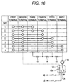
- Fig. 16 shows the configuration of a circuit which is connected to the first to sixth terminals 2 to 7.
- the first terminal 2 is connected to the cathode of a battery as the body is grounded.
- the second terminal 3 is connected to an ignition switch through a coil 12a of a relay 12.
- the third terminal 4 is connected to the anode of the battery through a series circuit formed by resistors 13 to 15, a blower motor 16, and a contact 12b of the relay 12.
- the fourth terminal 5 is connected to a common contact point of the resistors 13 and 14, and the fifth terminal 6 is connected to a common contact point of the resistors 14 and 15, and the sixth terminal 7 is directly connected to the blower motor 16.
- the relay 12 is turned on in correspondence with the operation of the ignition switch, and one end of the blower motor 16 is connected to the anode of the battery.
- the other end of the blower motor 16 is connected to the cathode of the battery through the resistors 13 to 15 corresponding to the air supplying position. Consequently, a current corresponding to a resistance value flows across the blower motor 16, and the blower motor 16 rotates in correspondence with the magnitude of the current. Therefore, it is possible to supply air to the interior of the vehicle compartment with four-step intensity corresponding to the air supplying position.
- the above-described blower switch is capable of coping with only up to four steps with the single contact because of the above-described structure of the contact. For this reason, in a case where five-step switching is required, it is necessary to use two contacts. Hence, there are drawbacks in that the structure becomes complex, and that the external size of the blower switch becomes large in size.
- the invention has been devised in view of the above-described circumstances, and its object is to provide a rotary switch which is capable of increasing the number of contacts without enlarging the external shape while using a single contact.
- a rotary switch comprising: an insulator provided with a plurality of terminals respectively having fixed contacts; a contact having a plurality of arm portions, movable contacts respectively provided on distal ends of the arm portions being respectively adapted to slide on the fixed contacts as the contact rotates; and urging means for imparting contact forces with respect to the fixed contacts to the movable contacts by urging a center of rotation of the contact, particular ones of the fixed contacts being made electrically conductive in correspondence with a rotated position of the contact, wherein a particular one of the arm portions in the contact is set to be short, and angles between respective ones of the arm portions are set such that the contact forces of the movable contacts with respect to the fixed contacts assume magnitudes corresponding to a load connected to the fixed contacts.
- the movable contacts provided on the distal ends of the arm portions of the contact slide on the fixed contacts, so that particular ones of fixed contacts are made electrically conductive through the contact.
- the fixed contacts where the movable contacts are brought into contact can be arranged at concentric positions. Hence, it becomes possible to increase the number of contacts without enlarging the external shape.
- an arrangement may be provided such that the fixed contact with which the movable contact with a large contact force is brought into contact is connected to a large-current load, while the fixed contact with which the movable contact with a small contact force is brought into contact is connected to an energizing means for energizing the large-current load.
- FIG. 1 to 14 a description will be given of an embodiment in which the invention is applied to a blower switch for a vehicle.
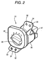
- Fig. 2 is a perspective view of the blower switch
- Fig. 3 is an exploded perspective view of the blower switch.
- a blower switch (corresponding to a rotary switch) 21 includes an operation knob complete 22, a compression coil spring 23, a contact 24, and an insulator complete 25.
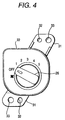
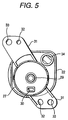
- Fig. 4 is a front view of the operation knob complete 22, and Fig. 5 is a rear view thereof.
- the operation knob complete 22 is provided with an operation knob 26.
- an "OFF" position is set, and an air supplying position "1,” an air supplying position "2,” an air supplying position "3,” an air supplying position “4,” and an air supplying position "5" are respectively set at each predetermined angle (22.5°) in correspondence with the intensity of air flow.
- This operation knob complete 22 is for transmitting the rotational operation of the operation knob 26 to the contact 24, and the operation knob 26 is adapted to click at the "OFF" position and each air supplying position at each predetermined angle (22.5°) by an clicking mechanism (not shown).
- An annular skirt portion 27 is formed on the rear surface of the operation knob complete 22, and the insulator complete 25 is adapted to be fitted to the skirt portion 27 (see Fig. 11).
- a rotor 28 formed integrally with the operation knob 26 is provided within the skirt portion 27, and the rotor 28 is adapted to rotate as the operation knob 26 is rotated.
- a hollow cylindrical portion 29 (see Fig. 11) is formed projectingly at the center of the rotor 28, and the contact 24 is fitted to the hollow cylindrical portion 29 (see Fig. 11). Further, a recessed portion 30 is formed in the rotor 28.
- a pair of attaching portions 31 are integrally provided on the operation knob complete 22, and a positioning hole 32 and a screw inserting hole 33 are formed in each of the attaching portions 31.
- the blower switch 21 can be fixed at a portion subject to attachment by threadedly engaging screws in the screw inserting holes 33 in the state in which projections formed on the portion subject to attachment are inserted in the positioning holes 32.
- a lamp insertion hole 34 is formed in the rear surface of the operation knob complete 22, and as a lamp 35 (see Fig. 3) inserted in the lamp insertion hole 34 emits light, the figure of a fan and each numeral provided on the front surface of the operation knob complete 22 are lit up.
- Fig. 6 is a front view of the contact 24, and Fig. 7 is a rear view thereof.
- a hollow cylindrical portion 36 is formed projectingly at the center of the contact 24, and the hollow cylindrical portion 36 is fitted over an outer periphery of the hollow cylindrical portion 29 formed on the rotor 28 of the operation knob complete 22.
- the iii 23 is interposed between the insulator complete 25 and the contact 24 (see Fig. 11).
- An engaging projection 24a is formed on the contact 24, and as the engaging projection 24a is retained at the recessed portion 30 formed in the rotor 28, the rotational operation of the operation knob 26 is transmitted to the rotor 28.
- the contract 24 is formed with first to third arm portions 37 to 39.
- First to third movable contacts 37a to 39a are respectively formed on distal ends of these first to third arm portions 37 to 39, and these movable contacts 37a to 39a are adapted to slide on the insulator complete 25.
- the length of the first arm portion 37 is set to be shorter than the length of the second and third arm portions 38 and 39, and the angle between the first and second arm portions 37 and 38 is set to be small.
- the contact forces of the first and third movable contacts 37a and 39a are set to be substantially identical, and the contact force of the second movable contact 38a is set to be smaller than the contact forces of the first and third movable contacts 37a and 39a.
- Fig. 8 is a front view of the insulator complete 25
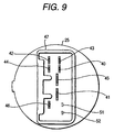
- Fig. 9 is a rear view thereof.
- first to seventh terminals 40 to 46 are fitted to the insulator complete 25
- first to seventh fixed contacts 40a to 46a are respectively provided on these terminals 40 to 46 at positions located at the front surface of the insulator complete 25.
- the first and second fixed contacts 40a and 41a are formed in semi-annular shapes, and the first fixed contact 40a is provided on the inner side of the second fixed contact 41a.
- the first and second fixed contacts 40a and 41a are provided at concentric positions such that their portions angularly overlap with each other.
- land portions 48 to 50 which are flush with the first to third terminals 40 to 42, are formed on the insulator complete 25 in correspondence with these terminals 40 to 42.
- a connector 47 is provided on the rear surface of the insulator complete 25. This connector 47 is provided with terminals 51 and 52 for turning on the lamp 35 in addition to the aforementioned terminals 40 to 46.
- Fig. 1 shows the positional relationship between the contact 24 and the insulator complete 25. In this case, the position of the contact 24 is shown in the state in which the operation knob 26 has been operated to the "OFF" position.
- the first movable contact 37a of the contact 24 is located on the first land portion 48 adjacent to the first fixed contact 40a
- the second movable contact 38a is located on the second land portion 49 adjacent to the second fixed contact 41a
- the third movable contact 39a is located on the third land portion 50 adjacent to the third fixed contact 42a.
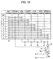
- Fig. 10 shows the configuration of a circuit connected to the first to seventh terminals 40 to 46.
- the first terminal 40 is connected to the cathode of a battery as the body is grounded.
- the second terminal 41 is connected to an ignition switch through a coil 53a of a relay (corresponding to an energizing means) 53.
- the third terminal 42 is connected to the anode of the battery through a series circuit formed by resistors 54 to 57, a blower motor (max. 200-Watt level) 58, and a contact 53b of the relay 53.
- the fourth terminal 43 is connected to a common contact point of the resistors 54 and 55
- the fifth terminal 44 is connected to a common contact point of the resistors 55 and 56
- the sixth terminal 45 is connected to a common contact point of the resistors 56 and 57.
- the seventh terminal 46 is directly connected to the blower motor 58.
- the relay 53 is turned on in correspondence with the operation of the ignition switch, and one end of the blower motor 58 is connected to the anode of the battery.
- the other end of the blower motor 58 is connected to the cathode of the battery through the resistors 54 to 57 corresponding to the air supplying position. Consequently, a current corresponding to a resistance value flows across the blower motor 58, and the blower motor 58 rotates in correspondence with the magnitude of the current. Therefore, it is possible to supply air to the interior of the vehicle compartment with five-step intensity corresponding to the air supplying position.
- Fig. 11 shows the cross section of principal portions of the operation knob complete 22.
- the attachment length x of the compression coil spring 23 is a value in which the thicknesswise dimension C of the terminal, the dimension D from the contact position of the contact 24 with respect to the terminal to the contact position thereof with respect to the compression coil spring 23, and the dimension E from the fitting surface of the rotor 28 to the contact surface thereof with respect to the compression coil spring 23 are subtracted from a value obtained by adding together the dimension A from the fitting surface of the rotor 28 to an end surface of the rotor 28 and the dimension B from the end surface of the rotor 28 to the terminal fitting surface of the insulator complete 25.
- the contact force Fs of the total contacts is a value in which the attaching load w is added to a value in which a value obtained by subtracting the attachment length x from the natural length 1 of the compression coil spring 23 is multiplied by the spring constant k.
- the attachment length x of the compression coil spring 23 is designed so as to be the natural length 1, the contact force Fs of the contacts is ideally constituted by the attachment load w alone.
- the contact force of a predetermined movable contact can be determined by multiplying by the attachment load w the ratio of the area of a triangle formed by connecting two movable contacts a other than the predetermined movable contact and the center of rotation of the contact 24 to the area of a triangle formed by connecting the three movable contacts 37a to 39a.
- the contact center of gravity in this embodiment (the position where the areas of the three triangles agree with each other) is offset from the center of rotation (the urging center), as shown in Fig. 12.
- the contact center of gravity and the urging center agree with each other, although the contact forces of the movable contacts 37a to 39a agree with each other, the contact forces of the movable contacts 37a to 39a vary in correspondence with the portion of offset from the contact center of gravity.
- the areas of the triangles formed by connecting the center of rotation and the two movable contacts of the movable contacts 37a to 39a in the contact 24, as shown in Fig. 13, are respectively determined.
- the area of a triangle can be obtained by the length of the base ⁇ height / 2
- the ratio among the contact force of the first movable contact 37a, the contact force of the second movable contact 38a, and the contact force of the third movable contact 39a becomes 1 : 2.1 : 2.2.
- the contact force of the second movable contact 38a provided on the second arm portion 38 is one-half of the contact force of the third movable contact 39a provided on the third arm portion 39.
- the first arm portion 37 is shorter than the third arm portion 39, the contact force of the first movable contact 37a provided on the first arm portion 37 and the contact force of the second movable contact 38a provided on the second arm portion 38 are substantially identical.
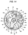
- the contact 24 rotates to the position shown in Fig. 14 in conjunction with the rotation of the operation knob 26. Namely, the first movable contact 37a leaves the first land portion 48 and moves onto the first fixed contact 40a, the second movable contact 38a leaves the second land portion 49 and moves onto the second fixed contact 41a, and the third movable contact 39a leaves the third land portion 50 and moves onto the third fixed contact 42a. Consequently, as shown in Fig. 10, the first terminal 40 and the second terminal 41, the third terminal 42 are made electrically conductive through the contact 24.
- the contact 24 rotates further, and the third movable contact 39a is located at the second fixed contact 41a.
- the on state of the contact 53b of the relay 53 is maintained, so that the blower motor 58 is energized through the resistors 55 to 57.
- the energizing current flowing across the blower motor 58 increases, so that the number of revolution of the blower motor 58 increases, and the rate of air supply to the interior of the vehicle compartment increases correspondingly.
- blower switch 21 since the blower switch 21 is connected so as to directly switch off a large energizing current flowing across the blower motor 58, it is necessary to set a large contact force for the movable contact where the energizing current to the blower motor 58 flows. Nevertheless, if attention is focused on the second movable contact 38a, which is connected to the coil 53a of the relay 53 through the second fixed contact 41a, its energizing current is smaller than the energizing current to the blower motor 58. Therefore, no hindrance is caused even if the contact force of the second movable contact 38a is set to be smaller than the contact forces of the first and third movable contacts 37a and 39a.
- the length of the second arm portion 38 in the contact 24 is formed to be shorter than the other arm portions 37 and 39, the first and second fixed contacts 40a and 41a where the first and second movable contacts 37a and 38a are brought into contact can be provided at concentric positions. Accordingly, unlike the conventional example in which the first to third arm portions in the contact are formed with identical lengths, the intensity of air supply can be arranged with five-step switching by adding a fixed contact without enlarging the blower switch 21.
- the angles between respective ones of the arm portions 37 to 39 in the contact 24 are set such that the contact forces of the movable contacts 37a to 39a with respect to the fixed contacts 40a to 46a assume magnitudes corresponding to the relay 53 connected to the relevant fixed contacts 40a to 46a or the blower motor 58. Therefore, no hindrance is caused to the energization for each load even if the contact forces of the movable contacts 37a to 39a differ by setting the length of the first arm portion 37 among the arm portions 37 to 39 of the contact 24 to be short, as described above.
- the intensity of air supply is not limited to five steps, and may be arranged in six steps or more.
- the blower motor 58 may be energized through a power transistor instead of the relay 53.
- a blower motor for an air conditioner for a rear seat may be connected to the fixed contact added in the blower switch 21, and the blower motor for an air conditioner for a rear seat may be controlled by the operation of the blower switch 21.
- the circuit which is connected to the fixed contacts where the movable contacts with small contact forces are brought into contact is not limited to the coil of the relay, and in a case where a plurality of motors are directly switched off by the rotary switch, motors with small energizing currents may be directly switched off.
- the invention is applicable not only to the blower switch but also to various other switches.
- a particular one of the arm portions in the contact is set to be short, and angles between respective ones of the arm portions are set such that the contact forces of the movable contacts with respect to the fixed contacts assume magnitudes corresponding to a load connected to the fixed contacts. Accordingly, an outstanding advantage can be offered in that the fixed contacts can be provided at concentric positions, and the number of contacts can be increased without enlarging the external shape while using a single contact.
Landscapes
- Rotary Switch, Piano Key Switch, And Lever Switch (AREA)
- Tumbler Switches (AREA)
Abstract
Description
Claims (3)
- A rotary switch comprising:an insulator provided with a plurality of terminals respectively having fixed contacts;a contact having a plurality of arm portions, said arm portions having movable contacts respectively on distal ends thereof, said fixed contacts slide on said arm portions, respectively in response to rotation of said contact; andurging means for imparting contact forces with respect to said fixed contacts to said movable contacts by urging a center of rotation of said contact, said fixed contacts to be selected made electrically conductive in correspondence with a rotated position of said contact,
wherein at least one said arm portion in said contact is set to be short as compare with the other, and angles defined between respective ones of said arm portions are set such that the contact forces of said movable contacts with respect to said fixed contacts in magnitudes corresponds to a load connected to said fixed contacts. - The rotary switch according to claim 1, wherein said fixed contact with which said movable contact with a large contact force is brought into contact is connected to a large-current load, and further comprising:energizing means for energizing the large-current load, said fixed contact with which said movable contact with a small contact force is brought into contact is connected to an energizing means.
- The rotary switch according to claim 2, wherein said energizing means is a relay.
Applications Claiming Priority (2)
| Application Number | Priority Date | Filing Date | Title |
|---|---|---|---|
| JP21061199 | 1999-07-26 | ||
| JP21061199A JP3802998B2 (en) | 1999-07-26 | 1999-07-26 | Rotary switch |
Publications (3)
| Publication Number | Publication Date |
|---|---|
| EP1073079A2 true EP1073079A2 (en) | 2001-01-31 |
| EP1073079A3 EP1073079A3 (en) | 2002-10-16 |
| EP1073079B1 EP1073079B1 (en) | 2008-09-10 |
Family
ID=16592201
Family Applications (1)
| Application Number | Title | Priority Date | Filing Date |
|---|---|---|---|
| EP00115941A Expired - Lifetime EP1073079B1 (en) | 1999-07-26 | 2000-07-25 | Rotary switch |
Country Status (4)
| Country | Link |
|---|---|
| US (1) | US6674183B1 (en) |
| EP (1) | EP1073079B1 (en) |
| JP (1) | JP3802998B2 (en) |
| DE (1) | DE60040193D1 (en) |
Cited By (3)
| Publication number | Priority date | Publication date | Assignee | Title |
|---|---|---|---|---|
| FR2884961A1 (en) * | 2005-04-26 | 2006-10-27 | Valeo Systemes Thermiques | ROTARY CONTROL BUTTON FOR VARIABLE SETPOINT INFORMATION, USING A POTENTIOMETRIC DEVICE |
| EP1881514A1 (en) * | 2006-07-18 | 2008-01-23 | Valeo Systèmes Thermiques | Control device with position detection |
| EP1972530B1 (en) * | 2006-01-12 | 2016-02-24 | Honda Motor Co., Ltd. | Side stand switch |
Families Citing this family (10)
| Publication number | Priority date | Publication date | Assignee | Title |
|---|---|---|---|---|
| US7495187B2 (en) * | 2005-09-02 | 2009-02-24 | Lear Corporation | Electrical switch |
| JP4833808B2 (en) * | 2006-01-12 | 2011-12-07 | 本田技研工業株式会社 | Side stand switch |
| US20080121510A1 (en) * | 2006-03-13 | 2008-05-29 | Von Kruchten Markus | Switchable blower motor resistor for hvac application |
| CN102598176B (en) * | 2010-03-23 | 2014-06-25 | 华为技术有限公司 | Switching method and device, its use and products |
| CN102157291B (en) * | 2010-12-24 | 2013-09-11 | 华为机器有限公司 | Switch connector |
| JP5802063B2 (en) * | 2011-06-20 | 2015-10-28 | 株式会社ヴァレオジャパン | Contact member mounting structure |
| FR2982994B1 (en) * | 2011-11-21 | 2014-01-10 | Sc2N Sa | ELECTRIC CONTACT SWITCH |
| JP2013114886A (en) * | 2011-11-29 | 2013-06-10 | Hosiden Corp | Movable contact and contact structure with the same |
| KR101936896B1 (en) * | 2017-06-26 | 2019-01-11 | 경창산업주식회사 | Shift Control Device with Button |
| US10505327B1 (en) * | 2017-12-17 | 2019-12-10 | Satyajit Patwardhan | Orientation agnostic electrical connector |
Family Cites Families (14)
| Publication number | Priority date | Publication date | Assignee | Title |
|---|---|---|---|---|
| DE443698C (en) * | 1926-03-07 | 1927-05-05 | Alexis Ulitovsky Dr Ing | Multiple switch for low current measurements |
| US4433607A (en) * | 1981-10-06 | 1984-02-28 | Westinghouse Electric Corp. | Switch for very large DC currents |
| IT8322511V0 (en) * | 1983-07-27 | 1983-07-27 | Sace Spa | ELECTRIC CURRENT LIMIT SWITCH WITH REMOTE CONTROL SUITABLE FOR A HIGH NUMBER OF MANEUVERS. |
| US4748297A (en) * | 1986-07-11 | 1988-05-31 | Carlingswitch, Inc. | Rotary switch |
| US4876416A (en) * | 1989-02-03 | 1989-10-24 | Actron Manufacturing Company | Multiple position rotary switch |
| US4945195A (en) * | 1989-03-20 | 1990-07-31 | C & K Components, Inc. | Rotary switch |
| JPH03253419A (en) * | 1990-03-01 | 1991-11-12 | Harada Ind Co Ltd | Actuator control device for automobile air conditioner |
| US5161422A (en) * | 1991-07-12 | 1992-11-10 | Prince Corporation | Universal control for electrically controlled vehicle transmission |
| US5691612A (en) * | 1996-01-29 | 1997-11-25 | Eaton Corporation | Windshield wiper control |
| JP3947307B2 (en) * | 1997-06-30 | 2007-07-18 | 株式会社鷺宮製作所 | Micro switch for high current |
| JP3213573B2 (en) * | 1997-10-30 | 2001-10-02 | 松下電工株式会社 | Control device with built-in switch |
| UA61989C2 (en) * | 1998-12-01 | 2003-12-15 | Shneider Electr Ind S A | Electromechanical contactor |
| JP2001028224A (en) * | 1999-07-14 | 2001-01-30 | Matsushita Electric Ind Co Ltd | Lever switch and composite switch using the same |
| US6222139B1 (en) * | 1999-09-15 | 2001-04-24 | General Electric Company | Rotary electric switch and contact therefore |
-
1999
- 1999-07-26 JP JP21061199A patent/JP3802998B2/en not_active Expired - Fee Related
-
2000
- 2000-07-25 EP EP00115941A patent/EP1073079B1/en not_active Expired - Lifetime
- 2000-07-25 DE DE60040193T patent/DE60040193D1/en not_active Expired - Lifetime
- 2000-07-26 US US09/625,955 patent/US6674183B1/en not_active Expired - Lifetime
Cited By (4)
| Publication number | Priority date | Publication date | Assignee | Title |
|---|---|---|---|---|
| FR2884961A1 (en) * | 2005-04-26 | 2006-10-27 | Valeo Systemes Thermiques | ROTARY CONTROL BUTTON FOR VARIABLE SETPOINT INFORMATION, USING A POTENTIOMETRIC DEVICE |
| EP1972530B1 (en) * | 2006-01-12 | 2016-02-24 | Honda Motor Co., Ltd. | Side stand switch |
| EP1881514A1 (en) * | 2006-07-18 | 2008-01-23 | Valeo Systèmes Thermiques | Control device with position detection |
| FR2904141A1 (en) * | 2006-07-18 | 2008-01-25 | Valeo Systemes Thermiques | POSITION DETECTION CONTROL DEVICE. |
Also Published As
| Publication number | Publication date |
|---|---|
| DE60040193D1 (en) | 2008-10-23 |
| US6674183B1 (en) | 2004-01-06 |
| EP1073079B1 (en) | 2008-09-10 |
| JP3802998B2 (en) | 2006-08-02 |
| EP1073079A3 (en) | 2002-10-16 |
| JP2001035311A (en) | 2001-02-09 |
Similar Documents
| Publication | Publication Date | Title |
|---|---|---|
| US6674183B1 (en) | Rotary switch with rotatable contact | |
| JP3574709B2 (en) | Composite switch lever device for automobile | |
| US5049709A (en) | Index rotary switch with rotor contact member having L-shaped arms | |
| US5755526A (en) | Ball and socket joint | |
| EP1323580B1 (en) | Multiple switch module | |
| US6227912B1 (en) | Structure of lamp socket | |
| JP3038639B2 (en) | Assembly structure of lever switch | |
| US6596956B1 (en) | SPDT switch with multiple contact arrangement | |
| US6756549B2 (en) | Power control apparatus | |
| US5773774A (en) | Electrical switch with omega shaped return spring | |
| US6743997B2 (en) | Rocker switch | |
| US7067744B2 (en) | Knob assembly | |
| JPH031501A (en) | Variable resistor | |
| US6111208A (en) | Modular electrical switch | |
| US6855896B2 (en) | Vehicular switch | |
| EP4060702B1 (en) | Power switch | |
| JPS58223220A (en) | Electric rotary switch | |
| JPH09147687A (en) | Lever combination switch | |
| US4975549A (en) | Multiple terminal switch apparatus | |
| JP3435903B2 (en) | Rotary switch device for vehicle combination switch | |
| JPH06162864A (en) | Lever operation switching type terminal block unit | |
| US7057121B2 (en) | Low-current starter switch for vehicles and starter gear comprising said switch | |
| JP2020136023A (en) | Dial type operation switch device | |
| JPH07117627A (en) | Rotational position detector for switch | |
| US5235213A (en) | Electrical control selector for controlling at least one actuator between a plurality of discrete positions |
Legal Events
| Date | Code | Title | Description |
|---|---|---|---|
| PUAI | Public reference made under article 153(3) epc to a published international application that has entered the european phase |
Free format text: ORIGINAL CODE: 0009012 |
|
| AK | Designated contracting states |
Kind code of ref document: A2 Designated state(s): AT BE CH CY DE DK ES FI FR GB GR IE IT LI LU MC NL PT SE |
|
| AX | Request for extension of the european patent |
Free format text: AL;LT;LV;MK;RO;SI |
|
| PUAL | Search report despatched |
Free format text: ORIGINAL CODE: 0009013 |
|
| AK | Designated contracting states |
Kind code of ref document: A3 Designated state(s): AT BE CH CY DE DK ES FI FR GB GR IE IT LI LU MC NL PT SE |
|
| AX | Request for extension of the european patent |
Free format text: AL;LT;LV;MK;RO;SI |
|
| RIC1 | Information provided on ipc code assigned before grant |
Free format text: 7H 01H 21/12 A, 7H 01H 19/58 B |
|
| 17P | Request for examination filed |
Effective date: 20021126 |
|
| AKX | Designation fees paid |
Designated state(s): DE FR GB |
|
| 17Q | First examination report despatched |
Effective date: 20061227 |
|
| 17Q | First examination report despatched |
Effective date: 20061227 |
|
| GRAP | Despatch of communication of intention to grant a patent |
Free format text: ORIGINAL CODE: EPIDOSNIGR1 |
|
| RAP1 | Party data changed (applicant data changed or rights of an application transferred) |
Owner name: KABUSHIKI KAISHA TOKAI RIKA DENKI SEISAKUSHO |
|
| GRAS | Grant fee paid |
Free format text: ORIGINAL CODE: EPIDOSNIGR3 |
|
| GRAA | (expected) grant |
Free format text: ORIGINAL CODE: 0009210 |
|
| AK | Designated contracting states |
Kind code of ref document: B1 Designated state(s): DE FR GB |
|
| REG | Reference to a national code |
Ref country code: GB Ref legal event code: FG4D |
|
| REF | Corresponds to: |
Ref document number: 60040193 Country of ref document: DE Date of ref document: 20081023 Kind code of ref document: P |
|
| PLBE | No opposition filed within time limit |
Free format text: ORIGINAL CODE: 0009261 |
|
| STAA | Information on the status of an ep patent application or granted ep patent |
Free format text: STATUS: NO OPPOSITION FILED WITHIN TIME LIMIT |
|
| 26N | No opposition filed |
Effective date: 20090611 |
|
| REG | Reference to a national code |
Ref country code: DE Ref legal event code: R084 Ref document number: 60040193 Country of ref document: DE |
|
| REG | Reference to a national code |
Ref country code: FR Ref legal event code: PLFP Year of fee payment: 17 |
|
| REG | Reference to a national code |
Ref country code: FR Ref legal event code: PLFP Year of fee payment: 18 |
|
| PGFP | Annual fee paid to national office [announced via postgrant information from national office to epo] |
Ref country code: FR Payment date: 20170613 Year of fee payment: 18 |
|
| PGFP | Annual fee paid to national office [announced via postgrant information from national office to epo] |
Ref country code: DE Payment date: 20170719 Year of fee payment: 18 Ref country code: GB Payment date: 20170719 Year of fee payment: 18 |
|
| REG | Reference to a national code |
Ref country code: DE Ref legal event code: R119 Ref document number: 60040193 Country of ref document: DE |
|
| GBPC | Gb: european patent ceased through non-payment of renewal fee |
Effective date: 20180725 |
|
| PG25 | Lapsed in a contracting state [announced via postgrant information from national office to epo] |
Ref country code: DE Free format text: LAPSE BECAUSE OF NON-PAYMENT OF DUE FEES Effective date: 20190201 Ref country code: FR Free format text: LAPSE BECAUSE OF NON-PAYMENT OF DUE FEES Effective date: 20180731 Ref country code: GB Free format text: LAPSE BECAUSE OF NON-PAYMENT OF DUE FEES Effective date: 20180725 |