EP1072964A1 - Fixing apparatus comprising a release agent - Google Patents
Fixing apparatus comprising a release agent Download PDFInfo
- Publication number
- EP1072964A1 EP1072964A1 EP00116442A EP00116442A EP1072964A1 EP 1072964 A1 EP1072964 A1 EP 1072964A1 EP 00116442 A EP00116442 A EP 00116442A EP 00116442 A EP00116442 A EP 00116442A EP 1072964 A1 EP1072964 A1 EP 1072964A1
- Authority
- EP
- European Patent Office
- Prior art keywords
- fixing
- temperature
- releasing agent
- roller
- fixing member
- Prior art date
- Legal status (The legal status is an assumption and is not a legal conclusion. Google has not performed a legal analysis and makes no representation as to the accuracy of the status listed.)
- Granted
Links
- 239000000463 material Substances 0.000 claims abstract description 13
- 238000005086 pumping Methods 0.000 claims description 8
- 238000010438 heat treatment Methods 0.000 claims 1
- 239000003795 chemical substances by application Substances 0.000 description 128
- 238000004140 cleaning Methods 0.000 description 20
- 229920006395 saturated elastomer Polymers 0.000 description 14
- 238000001514 detection method Methods 0.000 description 6
- 238000000034 method Methods 0.000 description 6
- 229920002545 silicone oil Polymers 0.000 description 5
- 230000001276 controlling effect Effects 0.000 description 4
- 229920001971 elastomer Polymers 0.000 description 4
- 230000001105 regulatory effect Effects 0.000 description 4
- YCKRFDGAMUMZLT-UHFFFAOYSA-N Fluorine atom Chemical compound [F] YCKRFDGAMUMZLT-UHFFFAOYSA-N 0.000 description 3
- 229910052731 fluorine Inorganic materials 0.000 description 3
- 239000011737 fluorine Substances 0.000 description 3
- 238000004804 winding Methods 0.000 description 3
- 239000003086 colorant Substances 0.000 description 2
- 239000013013 elastic material Substances 0.000 description 2
- 229910052736 halogen Inorganic materials 0.000 description 2
- 150000002367 halogens Chemical class 0.000 description 2
- 239000002699 waste material Substances 0.000 description 2
- 230000002411 adverse Effects 0.000 description 1
- 230000007547 defect Effects 0.000 description 1
- 238000010586 diagram Methods 0.000 description 1
- 230000000694 effects Effects 0.000 description 1
- 239000004744 fabric Substances 0.000 description 1
- 239000005001 laminate film Substances 0.000 description 1
- 238000012986 modification Methods 0.000 description 1
- 230000004048 modification Effects 0.000 description 1
- 230000002093 peripheral effect Effects 0.000 description 1
- 238000011084 recovery Methods 0.000 description 1
- 230000000979 retarding effect Effects 0.000 description 1
- 238000011144 upstream manufacturing Methods 0.000 description 1
Images





Classifications
-
- G—PHYSICS
- G03—PHOTOGRAPHY; CINEMATOGRAPHY; ANALOGOUS TECHNIQUES USING WAVES OTHER THAN OPTICAL WAVES; ELECTROGRAPHY; HOLOGRAPHY
- G03G—ELECTROGRAPHY; ELECTROPHOTOGRAPHY; MAGNETOGRAPHY
- G03G15/00—Apparatus for electrographic processes using a charge pattern
- G03G15/20—Apparatus for electrographic processes using a charge pattern for fixing, e.g. by using heat
-
- G—PHYSICS
- G03—PHOTOGRAPHY; CINEMATOGRAPHY; ANALOGOUS TECHNIQUES USING WAVES OTHER THAN OPTICAL WAVES; ELECTROGRAPHY; HOLOGRAPHY
- G03G—ELECTROGRAPHY; ELECTROPHOTOGRAPHY; MAGNETOGRAPHY
- G03G15/00—Apparatus for electrographic processes using a charge pattern
- G03G15/20—Apparatus for electrographic processes using a charge pattern for fixing, e.g. by using heat
- G03G15/2003—Apparatus for electrographic processes using a charge pattern for fixing, e.g. by using heat using heat
- G03G15/2014—Apparatus for electrographic processes using a charge pattern for fixing, e.g. by using heat using heat using contact heat
- G03G15/2017—Structural details of the fixing unit in general, e.g. cooling means, heat shielding means
- G03G15/2025—Structural details of the fixing unit in general, e.g. cooling means, heat shielding means with special means for lubricating and/or cleaning the fixing unit, e.g. applying offset preventing fluid
-
- G—PHYSICS
- G03—PHOTOGRAPHY; CINEMATOGRAPHY; ANALOGOUS TECHNIQUES USING WAVES OTHER THAN OPTICAL WAVES; ELECTROGRAPHY; HOLOGRAPHY
- G03G—ELECTROGRAPHY; ELECTROPHOTOGRAPHY; MAGNETOGRAPHY
- G03G15/00—Apparatus for electrographic processes using a charge pattern
- G03G15/20—Apparatus for electrographic processes using a charge pattern for fixing, e.g. by using heat
- G03G15/2003—Apparatus for electrographic processes using a charge pattern for fixing, e.g. by using heat using heat
- G03G15/2014—Apparatus for electrographic processes using a charge pattern for fixing, e.g. by using heat using heat using contact heat
- G03G15/2064—Apparatus for electrographic processes using a charge pattern for fixing, e.g. by using heat using heat using contact heat combined with pressure
-
- G—PHYSICS
- G03—PHOTOGRAPHY; CINEMATOGRAPHY; ANALOGOUS TECHNIQUES USING WAVES OTHER THAN OPTICAL WAVES; ELECTROGRAPHY; HOLOGRAPHY
- G03G—ELECTROGRAPHY; ELECTROPHOTOGRAPHY; MAGNETOGRAPHY
- G03G2215/00—Apparatus for electrophotographic processes
- G03G2215/20—Details of the fixing device or porcess
- G03G2215/2003—Structural features of the fixing device
- G03G2215/2045—Variable fixing speed
-
- G—PHYSICS
- G03—PHOTOGRAPHY; CINEMATOGRAPHY; ANALOGOUS TECHNIQUES USING WAVES OTHER THAN OPTICAL WAVES; ELECTROGRAPHY; HOLOGRAPHY
- G03G—ELECTROGRAPHY; ELECTROPHOTOGRAPHY; MAGNETOGRAPHY
- G03G2215/00—Apparatus for electrophotographic processes
- G03G2215/20—Details of the fixing device or porcess
- G03G2215/2093—Release agent handling devices
Definitions
- the present invention relates to a fixing apparatus applied to image forming apparatuses such as a copying machine and a printer, particularly to an apparatus for applying a fixing member with a releasing agent.
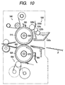
- Fig. 10 shows a fixing apparatus as a background art of the present invention.
- the fixing apparatus is constituted of a fixing roller 510 as a fixing rotating member which is rotatably disposed, a pressurizing roller 520 as a pressurizing rotating member which is pressed in contact with the fixing roller 510 and rotates, a releasing agent applying apparatus 530 as releasing agent applying means, cleaning apparatuses 540, 550, and the like. Additionally, heaters 560, 570 such as halogen lamps are disposed inside the fixing roller 510 and pressurizing roller 520, respectively.
- the releasing agent applying apparatus 530 is constituted of: a releasing agent reservoir 530a for containing releasing agents such as silicone oil; pumping rollers 530b, 530c for pumping the releasing agent from the releasing agent reservoir 530a; a applying roller 530d for applying the pumped releasing agent to the fixing roller 510; a regulating blade 530e, formed of elastic materials such as fluorine rubber, for regulating a releasing agent amount on the applying roller 530d to provide a constant amount; and the like.
- the releasing agent applying apparatus 530 is disposed on the downstream side of the rotation direction of the fixing roller 510 with respect to the thermistor 580.
- the fixing roller 510 and pressurizing roller 520 rotate, and the surface of the fixing roller 510 is applied with silicone oil as the releasing agent.
- the recording sheet P passes between the fixing roller 510 and the pressurizing roller 520, the recording sheet is pressurized and heated with substantially constant pressure and temperature from both front and back surfaces, an unfixed toner image is fixed and an image is formed on the recording sheet P.
- the recording sheet P with the image fixed thereto is separated from the pressurizing roller 520 by a lower separating pawl 680 and discharged to the outside.
- the releasing agent gains a high temperature.
- the fixing roller indicates a little temperature drop.
- the releasing agent present between the fixing roller and toner also has a high temperature, the fixing property is enhanced.
- the temperature of the releasing agent is low.
- the temperature of the fixing roller rapidly lowers. Additionally, since the low-temperature releasing agent exists between the fixing roller and toner surface, the fixing property is deteriorated. This is further remarkable in a low temperature environment.
- An object of the present invention is to provide a fixing apparatus which performs satisfactory fixing irrespective of temperature of a releasing agent.
- Another object of the present invention is to provide a fixing apparatus comprising: a fixing member for fixing an unfixed image onto a recording material; releasing agent applying means for applying a releasing agent to the fixing member; temperature detecting means for detecting temperature of the releasing agent; and control means for controlling a fixing condition in accordance with a detected temperature from the temperature detecting means.
- a four-drum laser beam printer provided with a plurality of light scanning means is shown as an image forming apparatus to which the present invention is applied in Figs. 8 and 9.
- Fig. 8 is a sectional view of an image forming apparatus (laser beam printer)
- Fig. 9 is a sectional view showing an image forming portion in the image forming apparatus, and as shown in Fig. 8 four image forming stations Pa, Pb, Pc, Pd as image forming means are arranged in line in an apparatus main body.
- the image forming stations Pa, Pb, Pc, Pd form images of respective colors of magenta, cyan, yellow, and black, and these are provided with photosensitive drums 1a, 1b, 1c, 1d as image bearers rotated in arrow directions shown in Fig. 9, respectively.
- a charging device 12a, 12b, 12c, 12d, a developing device 2a, 2b, 2c, 2d and a cleaner 4a, 4b, 4c, 4d are successively disposed along the rotation direction of each photosensitive drum 1a, 1b, 1c, 1d, and a transferring portion 3 is disposed under the respective photosensitive drums 1a, 1b, 1c, 1d.
- the transferring portion 3 includes a transferring belt 31 as recording material conveying means common to the respective image forming stations Pa to Pd and transferring charging devices 3a, 3b, 3c, 3d.
- a recording sheet P supplied from a sheet feeding cassette 61 as recording material supply means shown in Fig. 8 is supported on the transferring belt 31, conveyed to the respective image forming stations Pa to Pd, and successively subjected to transferring of the respective colors of toner images formed on the respective photosensitive drums 1a to 1d. Subsequently, when this transferring process ends, the recording sheet P is separated from the transferring belt 31 and conveyed to a fixing apparatus 5 by a conveying belt 62 as recording material guide means.
- the fixing apparatus 5 is constituted of a fixing roller (fixing rotating member) 51 as a rotatably disposed fixing member, a pressurizing roller (pressurizing rotating member) 52 as a separate fixing member which is pressed in contact with the fixing roller 51 and rotates, a releasing agent applying apparatus 53 as releasing agent applying means, and cleaning apparatuses 54, 55. Additionally, heaters 56, 57 such as halogen lamps are disposed inside the fixing roller 51 and pressurizing roller 52, respectively.
- thermoelectric motor 58, 59 are disposed to abut on the fixing roller 51 and pressurizing roller 52, respectively, and surface temperatures of the fixing roller 51 and pressurizing roller 52 are adjusted by controlling voltages to the heaters 56, 57 via a temperature adjustment circuit.
- the cleaning apparatus 54 and releasing agent applying apparatus 53 are attached to the fixing roller 51, the cleaning apparatus 54 cleans toner or the like offset on the fixing roller 51, and the releasing agent applying apparatus 53 applies releasing agents such as silicone oil to the fixing roller 51, so that separating of the recording sheet P from the fixing roller 51 is facilitated and the toner is prevented from being offset.
- the cleaning apparatus 54 is constituted of a cleaning web 54a of a strip-shaped heat-resistant non-woven cloth, a pressing roller 54b for pressing the cleaning web 54a onto the fixing roller 51, an unwinding roller 54c for feeding a new cleaning web 54a, a wind-up roller 54d for gradually winding up the cleaning web 54a whose cleaning ability is deteriorated by an adhering toner or the like, and the like, and the cleaning apparatus 54 is disposed on the upstream side of the rotation direction of the fixing roller 51 with respect to the thermistor 58 particularly to prevent the offset toner from adhering to the thermistor 58 or from causing detection defect in the thermistor 58.
- a method of winding up the cleaning web 54a comprises turning on a solenoid (not shown) when a counter judges that a predetermined number of sheets are copied, and operating a one-way clutch to wind up a predetermined amount of the cleaning web in a direction reverse to the rotation direction of the fixing roller 51. By winding up the cleaning web 54a in the reverse direction, the cleaning web 54a is prevented from being wound in the rotation direction of the fixing roller 51.
- the releasing agent applying apparatus 53 is constituted of: a releasing agent reservoir 53a for containing releasing agents such as silicone oil; pumping rollers 53b, 53c for pumping the releasing agent from the releasing agent reservoir 53a; a applying roller 53d for applying the pumped releasing agent to the fixing roller 51; a regulating blade 53e, formed of elastic materials such as fluorine rubber, for regulating a releasing agent amount on the applying roller 53d to provide a constant amount; and the like.
- the releasing agent applying apparatus 53 is disposed on the downstream side of the rotation direction of the fixing roller 51 with respect to the thermistor 58.
- a cleaning apparatus 55 constituted of a cleaning web 55a, pressing roller 55b, unwinding roller 55c, wing-up roller 55d, and the like is also attached to the pressurizing roller 52, and the cleaning apparatus 55 performs cleaning of the toner adhering to the pressurizing roller 52 via the fixing roller 51.
- the pressurizing roller 52 abuts on a releasing agent removing blade 60 as a releasing agent removing elastic member for removing an excess releasing agent remaining on the pressurizing roller 52. Additionally, when there is no releasing agent removing blade 60, an excess releasing agent is stored in a nip of the fixing roller 51 and pressurizing roller 52, the recording sheet P is stained, or an OHP transparent laminate film slips and failure occurs in approach to the nip.
- the releasing agent removing blade 60 Si rubber, fluorine rubber, or the like is used as a material, and the releasing agent removing blade 60 abuts on the pressurizing roller 52 with an appropriate approach amount in a forward or backward direction with respect to the rotation direction of the pressurizing roller.
- the fixing roller 51 and pressurizing roller 52 rotate, and the surface of the fixing roller 51 is applied with silicone oil as the releasing agent.
- the recording sheet P passes through the nip on which the fixing roller 51 and pressurizing roller 52 are pressurized to abut, the recording sheet is pressurized and heated with substantially constant pressure and temperature from both front and back surfaces, an unfixed toner image is fixed and a full-color image is formed on the recording sheet P.
- the recording sheet P with the image fixed thereto is separated from the pressurizing roller 52 by a lower separating pawl 68 and discharged to the outside.
- a thermistor 70 as temperature detecting means is disposed in the releasing agent reservoir 53a.
- Numeral 100 denotes control means, and the means receives a detected temperature from the thermistor 70 and can control a fixing temperature, pressure in the fixing nip, rotation speeds of the fixing and pressurizing rollers, supply timing of the recording material to the fixing apparatus, and the like.
- control is performed so as to set the fixing temperature to an optimum fixing condition in accordance with the releasing agent temperature detected by the thermistor 70.
- Fig. 3 is a chart showing time and releasing agent temperature change when the surface temperature of the fixing roller 51 is set to 180°C, and as shown in Fig. 3 the releasing agent temperature rises in several hours and is saturated at a certain temperature. Additionally, when the temperature is controlled (adjusted) to provide 180°C in the fixing apparatus 5 of the present embodiment, the releasing agent temperature is saturated at about 150°C.
- step S3 it is judged whether or not the releasing agent temperature detected by the thermistor 70 reaches a predetermined saturation temperature (step S3).
- a usual temperature control is performed. Namely, the temperature control is performed so that the fixing roller reaches a preset standard set temperature (step S4).
- fixing temperature control is put up. Namely, the temperature control is performed so that the set temperature of the fixing roller is higher than the standard set temperature (step S5). The aforementioned operation (operation of steps S2 to S5) is repeated until the power source is turned off (step S6).
- the surface temperature of the fixing roller 51 corresponds to about 1°C.
- the releasing agent temperature is about 30°C, and lower than a saturation temperature of 150°C by 120°C.
- the satisfactory fixing property can be obtained by raising the set temperature only by 12°C from the left state. Moreover, every time the releasing agent temperature gradually rises, the controlled temperature (set temperature) of the fixing roller 51 is gradually lowered. When the releasing agent temperature is saturated at 150°C, control is performed to return to the normal standard set temperature of the fixing roller. In a conventional type of a machine, irrespective of the releasing agent temperature, means for raising the fixing roller surface temperature only for the predetermined time only in the state of first run in the morning is used.
- the fixing property differs with a peripheral environment temperature or humidity around the machine
- a finer control can be performed.
- the fixing set temperature can be represented by the following equation by the environment temperature detected using external temperature detecting means 80 and the releasing agent temperature detected using the thermistor 70. ((releasing agent saturation temperature)-(releasing agent detected temperature))/10-(environment temperature)+15
- 15 is a correcting value.
- the releasing agent temperature or the like in the present embodiment differs by the constitution of the fixing apparatus or the set temperature of the fixing roller, the value is not necessarily limited.
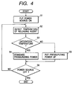
- Fig. 4 is a flowchart showing the fixing condition changing control procedure in the fixing apparatus of the present embodiment.
- an image forming apparatus similar to that of the aforementioned embodiment is used to perform a control shown in Fig. 4.
- the thermistor 70 as the temperature detecting means is disposed in the releasing agent reservoir 53a, and the control is performed to change a fixing pressurizing power, that is, a pressure in the nip on which the fixing roller and pressurizing roller are pressed to abut in accordance with the releasing agent temperature.
- step S1 when the power source is put on (step S1), the thermistor 70 detects the temperature of the releasing agent in the releasing agent reservoir 53a at a predetermined interval (step S2).
- the releasing agent temperature shows a behavior similar to that shown in Fig. 3. Namely, as shown in Fig. 3 the releasing agent temperature rises in several hours and is saturated at a certain temperature. Additionally, the temperature is saturated at about 150°C in the fixing apparatus 5 of the present embodiment.
- step S3 it is judged whether or not the releasing agent temperature detected by the thermistor 70 reaches the saturation temperature (step S3).
- the pressurizing power of the fixing roller 51 and pressurizing roller 52 are set to a standard pressurizing power (step S4).
- the pressurizing power is put up from the standard pressurizing power (step S5).
- the aforementioned operation (operation of steps S2 to S5) is repeated until the power source is turned off (step S6).
- the satisfactory fixing property can be obtained even in the state of first run in the morning by changing the pressurizing power of the fixing roller 51 and pressurizing roller 52 in accordance with the releasing agent temperature.
- the pressurizing power corresponds to a total pressure of about 1 kgf ( ⁇ 9.8 N).
- the releasing agent temperature is about 30°C, and lower than the saturation temperature of 150°C by 120°C.
- the releasing agent temperature and pressurizing power in the present embodiment differ with a fixing apparatus constitution, the value is not necessarily limited.
- the fixing property differs with the environment temperature and humidity around the machine, by further combining detection of the temperature and humidity of the environment where the machine is placed with the present embodiment, a finer control can be performed and the property is further enhanced.
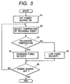
- FIG. 5 is a flowchart showing the fixing condition changing control procedure in the fixing apparatus of the present embodiment.
- an image forming apparatus similar to that of the aforementioned embodiment is used to perform a control shown in Fig. 5.
- the thermistor 70 as the temperature detecting means is disposed in the releasing agent reservoir 53a, and the control is performed to change a rotation speed of the fixing roller 51 and pressurizing roller 52 in accordance with the releasing agent temperature.
- the thermistor 70 detects the temperature of the releasing agent in the releasing agent reservoir 53a at a predetermined interval (step S2).
- the releasing agent temperature shows a behavior similar to that shown in Fig. 3. Namely, as shown in Fig. 3 the releasing agent temperature rises in several hours and is saturated at a certain temperature. Additionally, the temperature is saturated at about 150°C in the fixing apparatus 5 of the present embodiment.
- step S3 it is judged whether or not the releasing agent temperature detected by the thermistor 70 reaches the saturation temperature (step S3).
- the rotation speed (fixing velocity) of the fixing roller 51 and pressurizing roller 52 is set to a standard fixing velocity (step S4).
- the saturation temperature is not obtained, the fixing velocity is set to be low and slower than a standard fixing velocity (step S5).
- the aforementioned operation (operation of steps S2 to S5) is repeated until the power source is turned off (step S6).
- the satisfactory fixing property can be obtained even in the state of first run in the morning by changing the rotation speed of the fixing roller 51 and pressurizing roller 52 in accordance with the releasing agent temperature.
- the releasing agent temperature is about 30°C, and lower than the saturation temperature of 150°C by 120°C.
- the satisfactory fixing property can be obtained by setting the rotation speed of the fixing roller 51 and pressurizing roller 52 in the state of first run in the morning to be slower than that in the left state. Moreover, every time the releasing agent temperature gradually rises, the rotation speed of the fixing roller 51 and pressurizing roller 52 is gradually raised. When the releasing agent temperature is saturated at 150°C, the control is performed to return to the normal standard fixing velocity. In the present embodiment, since a necessary time for retarding the rotation speed is minimized, the property of a main body can be enhanced.
- the releasing agent temperature and rotation speed differ with the constitution of the fixing apparatus, these are not necessarily limited to the values described in the present embodiment.
- the fixing property differs with the environment temperature and humidity around the machine, by further combining the detection of the temperature and humidity of the environment where the machine is placed with the present embodiment, a finer control is possible and the property is further enhanced.
- Fig. 6 is a flowchart showing the fixing condition changing control procedure in the fixing apparatus of the present embodiment.
- an image forming apparatus similar to that of the aforementioned embodiment is used and a control is performed as shown in Fig. 6.
- the thermistor 70 as the temperature detecting means is disposed in the releasing agent reservoir 53a, and the control is performed to change a passing sheet interval, that is, the supply timing of the recording material to the fixing apparatus in accordance with the releasing agent temperature.
- the thermistor 70 detects the temperature of the releasing agent in the releasing agent reservoir 53a at a predetermined interval (step S2).
- the releasing agent temperature shows a behavior similar to that shown in Fig. 3. Namely, as shown in Fig. 3 the releasing agent temperature rises in several hours and is saturated at a certain temperature. Additionally, the temperature is saturated at about 150°C in the fixing apparatus 5 of the present embodiment.
- step S3 it is judged whether or not the releasing agent temperature detected by the thermistor 70 reaches the saturation temperature.
- the passing sheet interval is set to a standard passing sheet interval (step S4).
- the passing sheet interval is set to be larger than the standard passing sheet interval (step S5). The aforementioned operation (operation of steps S2 to S5) is repeated until the power source is turned off (step S6).
- the satisfactory fixing property can be obtained even in the state of first run in the morning by changing the passing sheet interval in accordance with the releasing agent temperature.
- the releasing agent temperature is about 30°C, and lower than the saturation temperature of 150°C by 120°C.
- the passing sheet interval in the state of first run in the morning is set to be larger than that in the left state, a time for recovering the temperature of the fixing roller after fixing one sheet is lengthened, a temperature recovering width of the fixing roller 51 increases, and the satisfactory fixing property can be obtained.
- the passing sheet interval is gradually reduced.
- the control is performed to return to the normal standard passing sheet interval. In the present embodiment, by increasing the passing sheet interval and subsequently gradually returning to the standard, wasteful time is minimized and the main body property can therefore be enhanced.
- the releasing agent temperature and passing sheet interval differ with the constitution of the fixing apparatus, these are not necessarily limited to the values described in the present embodiment.
- the fixing property differs with the environment temperature and humidity around the machine, by further combining the detection of the temperature and humidity of the environment in which the machine is placed with the present embodiment, a finer control is possible and the property is further enhanced.
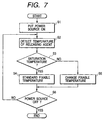
- Fig. 7 is a flowchart showing the fixing condition changing control procedure in the fixing apparatus of the present embodiment.
- an image forming apparatus similar to that of the aforementioned embodiment is used and a control is performed as shown in Fig. 7.
- the thermistor 70 as the temperature detecting means is disposed in the releasing agent reservoir 53a, and the control is performed to change the number of fixable sheets in the state of first run in the morning (to put it concretely, a fixable temperature) in accordance with the releasing agent temperature.
- the fixable temperature is a little lower than a set temperature, or a lower limit value when the value of the set temperature has a width, and indicates a minimum fixable temperature.
- the fixing property is deteriorated in the state of first run in the morning. Therefore, in a machine, irrespective of the releasing agent temperature, continuous copying is performed for a predetermined time after the power source is turned on, the copying is stopped when the fixing roller temperature lowers down to a certain temperature, a standby state continues until the fixing roller temperature is recovered, and the copying is restarted after the recovery.
- the fixing roller temperature state is not known in this control, the fixable temperature is uniformly determined. Even when the releasing agent temperature gradually rises and the fixing property is gradually enhanced, the fixable temperature is constant within the predetermined time from the state of first run in the morning and the number of sheets is small until the stop of the copying.
- the thermistor 70 detects the temperature of the releasing agent in the releasing agent reservoir 53a at a predetermined interval (step S2).
- the releasing agent temperature shows a behavior similar to that shown in Fig. 3. Namely, as shown in Fig. 3 the releasing agent temperature rises in several hours and is saturated at a certain temperature. Additionally, the temperature is saturated at about 150°C in the fixing apparatus 5 of the present embodiment.
- step S3 it is judged whether or not the releasing agent temperature detected by the thermistor 70 reaches the saturation temperature.
- the fixable temperature is set to a standard fixable temperature (step S4).
- the fixable temperature is set to be higher than the standard fixable temperature (step S5). The aforementioned operation (operation of steps S2 to S5) is repeated until the power source is turned off (step S6).
- the satisfactory fixing property can be obtained even in the state of first run in the morning by changing the fixable temperature in accordance with the releasing agent temperature.
- the releasing agent temperature is about 30°C, and lower than the saturation temperature of 150°C by 120°C.
- the fixable temperature is finely controlled in accordance with the releasing agent temperature.
- the fixable temperature rises, thereby quickly entering the standby mode. Moreover, when the releasing agent temperature gradually increases, the fixable temperature gradually lowers. Thereby, the number of copied sheets increases before rushing into the standby mode, and the property is enhanced.
- the releasing agent temperature and fixable temperature differ with the constitution of the fixing apparatus, these are not necessarily limited to the values described in the present embodiment.
- the fixing property differs with the environment temperature and humidity around the machine, by further combining the detection of the temperature and humidity of the environment where the machine is placed with the present embodiment, a finer control is possible and the property is further enhanced.
- the present invention provides a fixing apparatus which has a fixing member for fixing an unfixed image onto a recording material, releasing agent applying device for applying a releasing agent to the fixing member, temperature detecting device for detecting a temperature of the releasing agent, and control device for controlling a fixing condition based on a detected temperature from the temperature detecting device.
Landscapes
- Physics & Mathematics (AREA)
- General Physics & Mathematics (AREA)
- Fixing For Electrophotography (AREA)
Abstract
Description
Claims (16)
- A fixing apparatus comprising:a fixing member for fixing an unfixed image onto a recording material;releasing agent applying means for applying a releasing agent to said fixing member;temperature detecting means for detecting a temperature of said releasing agent; andcontrol means for controlling a fixing condition based on a detected temperature from said temperature detecting means.
- A fixing apparatus according to claim 1, wherein when the detected temperature from said temperature detecting means is lower than a preset releasing agent temperature, a fixing property by said fixing member is set to be higher than a preset standard fixing property.
- A fixing apparatus according to claim 2, wherein with a rise of said detected temperature said fixing property is set to become gradually lower.
- A fixing apparatus according to claim 1, wherein said fixing condition is the temperature of said fixing member.
- A fixing apparatus according to claim 4, wherein said fixing member is a roller, and includes a heat source inside.
- A fixing apparatus according to claim 1, further comprising a pressurizing member for forming a nip with said fixing member, said fixing condition being a pressure in said nip.
- A fixing apparatus according to claim 1, wherein said fixing member is movable, and said fixing condition is a movement speed of said fixing member.
- A fixing apparatus according to claim 7, wherein said fixing member is a rotating member.
- A fixing apparatus according to claim 8, wherein said fixing member is a roller.
- A fixing apparatus according to claim 1, wherein said fixing condition is a timing of a recording material supplied to said fixing member.
- A fixing apparatus according to claim 1, further comprising environment detecting means for detecting an environment condition, wherein said fixing condition is further controlled in accordance with a detected result from said environment detecting means.
- A fixing apparatus according to claim 11, wherein said environment condition is an environment temperature.
- A fixing apparatus according to claim 11, wherein said environment condition is an environment humidity.
- A fixing apparatus according to claim 1, wherein said fixing member is a heating roller, and said releasing agent applying means is in contact with said fixing member.
- A fixing apparatus according to claim 14, wherein said releasing agent applying means includes a reservoir for containing the releasing agent, a pumping roller for pumping the releasing agent from said reservoir, and a applying roller for applying the releasing agent pumped by said pumping roller to said fixing member, and said applying roller is in contact with said fixing member.
- A fixing apparatus according to claim 1, further comprising a pressurizing member for forming a nip with said fixing member, wherein the recording material bearing the unfixed image is held and conveyed by said nip, and the unfixed image is fixed onto the recording material.
Applications Claiming Priority (2)
| Application Number | Priority Date | Filing Date | Title |
|---|---|---|---|
| JP21716899 | 1999-07-30 | ||
| JP21716899A JP3420534B2 (en) | 1999-07-30 | 1999-07-30 | Fixing device and image forming device |
Publications (2)
| Publication Number | Publication Date |
|---|---|
| EP1072964A1 true EP1072964A1 (en) | 2001-01-31 |
| EP1072964B1 EP1072964B1 (en) | 2003-03-05 |
Family
ID=16699934
Family Applications (1)
| Application Number | Title | Priority Date | Filing Date |
|---|---|---|---|
| EP00116442A Expired - Lifetime EP1072964B1 (en) | 1999-07-30 | 2000-07-28 | Fixing apparatus comprising a release agent |
Country Status (4)
| Country | Link |
|---|---|
| US (1) | US6487381B1 (en) |
| EP (1) | EP1072964B1 (en) |
| JP (1) | JP3420534B2 (en) |
| DE (1) | DE60001523T2 (en) |
Cited By (1)
| Publication number | Priority date | Publication date | Assignee | Title |
|---|---|---|---|---|
| EP2246742A3 (en) * | 2009-04-27 | 2011-10-26 | Ricoh Company, Ltd. | Fixing device and image forming apparatus incorporating same |
Families Citing this family (5)
| Publication number | Priority date | Publication date | Assignee | Title |
|---|---|---|---|---|
| JP4387740B2 (en) * | 2003-09-24 | 2009-12-24 | キヤノン株式会社 | Fixing device |
| JP2008015444A (en) * | 2006-06-05 | 2008-01-24 | Sharp Corp | Fixing device with cleaning mechanism and image forming apparatus having the same |
| JP4810407B2 (en) | 2006-11-15 | 2011-11-09 | キヤノン株式会社 | Sheet feeding apparatus and image forming apparatus |
| JP5083769B2 (en) * | 2008-03-18 | 2012-11-28 | 株式会社リコー | Image forming apparatus |
| JP5538878B2 (en) * | 2009-12-28 | 2014-07-02 | キヤノン株式会社 | Image forming apparatus |
Citations (3)
| Publication number | Priority date | Publication date | Assignee | Title |
|---|---|---|---|---|
| US4087676A (en) * | 1975-12-26 | 1978-05-02 | Rank Xerox Ltd. | Fixing apparatus with heat and pressure for electrophotographic copiers |
| US4563073A (en) * | 1984-10-31 | 1986-01-07 | Xerox Corporation | Low mass heat and pressure fuser and release agent management system therefor |
| EP0821289A1 (en) * | 1996-07-26 | 1998-01-28 | Konica Corporation | Image forming apparatus |
Family Cites Families (12)
| Publication number | Priority date | Publication date | Assignee | Title |
|---|---|---|---|---|
| JPS548539A (en) | 1977-06-21 | 1979-01-22 | Canon Inc | Liquid feeder |
| US4193681A (en) * | 1977-06-30 | 1980-03-18 | Canon Kabushiki Kaisha | Liquid feeding device |
| JPH0442186A (en) * | 1990-06-08 | 1992-02-12 | Toshiba Corp | Fixing device |
| JP3118096B2 (en) | 1992-09-30 | 2000-12-18 | キヤノン株式会社 | Image forming device |
| JP3109698B2 (en) | 1992-09-30 | 2000-11-20 | キヤノン株式会社 | Image forming device |
| US5608508A (en) | 1994-03-25 | 1997-03-04 | Canon Kabushiki Kaisha | Rotatable member for fixing in which inorganic filler is contained in silicone rubber, and fixing device having the same |
| JPH07295422A (en) * | 1994-04-28 | 1995-11-10 | Canon Inc | Fixing device |
| JPH08202199A (en) | 1995-01-23 | 1996-08-09 | Canon Inc | Image forming device |
| JPH08328425A (en) | 1995-05-31 | 1996-12-13 | Canon Inc | Fixing device and image forming apparatus |
| US5729818A (en) | 1995-07-07 | 1998-03-17 | Canon Kabushiki Kaisha | Image forming apparatus having a fixing device and a conveyer means for conveying a recording member to the fixing device |
| JP3880208B2 (en) | 1997-07-28 | 2007-02-14 | キヤノン株式会社 | Heating and pressure fixing device and silicone rubber roller |
| JPH11133797A (en) * | 1997-10-31 | 1999-05-21 | Canon Inc | Image forming device |
-
1999
- 1999-07-30 JP JP21716899A patent/JP3420534B2/en not_active Expired - Fee Related
-
2000
- 2000-07-28 DE DE60001523T patent/DE60001523T2/en not_active Expired - Fee Related
- 2000-07-28 EP EP00116442A patent/EP1072964B1/en not_active Expired - Lifetime
- 2000-07-28 US US09/628,021 patent/US6487381B1/en not_active Expired - Fee Related
Patent Citations (3)
| Publication number | Priority date | Publication date | Assignee | Title |
|---|---|---|---|---|
| US4087676A (en) * | 1975-12-26 | 1978-05-02 | Rank Xerox Ltd. | Fixing apparatus with heat and pressure for electrophotographic copiers |
| US4563073A (en) * | 1984-10-31 | 1986-01-07 | Xerox Corporation | Low mass heat and pressure fuser and release agent management system therefor |
| EP0821289A1 (en) * | 1996-07-26 | 1998-01-28 | Konica Corporation | Image forming apparatus |
Cited By (2)
| Publication number | Priority date | Publication date | Assignee | Title |
|---|---|---|---|---|
| EP2246742A3 (en) * | 2009-04-27 | 2011-10-26 | Ricoh Company, Ltd. | Fixing device and image forming apparatus incorporating same |
| US8463150B2 (en) | 2009-04-27 | 2013-06-11 | Ricoh Company Limited | Fixing device and image forming apparatus incorporating same |
Also Published As
| Publication number | Publication date |
|---|---|
| DE60001523D1 (en) | 2003-04-10 |
| JP2001042698A (en) | 2001-02-16 |
| EP1072964B1 (en) | 2003-03-05 |
| US6487381B1 (en) | 2002-11-26 |
| DE60001523T2 (en) | 2003-10-02 |
| JP3420534B2 (en) | 2003-06-23 |
Similar Documents
| Publication | Publication Date | Title |
|---|---|---|
| US6807386B2 (en) | Fixing device and image forming apparatus | |
| US7907861B2 (en) | Image heating apparatus for heating an image on a recording material to different temperatures in different modes | |
| JP3739000B2 (en) | Fixing device and image forming apparatus having the fixing device | |
| US8687992B2 (en) | Image heating apparatus | |
| CN101566811A (en) | Image forming apparatus, printing method applicable to image forming apparatus, and program for implementing a printing process carried out by image forming apparatus | |
| US8958711B2 (en) | Image forming apparatus | |
| US5903799A (en) | Image heating apparatus with energization control | |
| EP1072964B1 (en) | Fixing apparatus comprising a release agent | |
| JPH11272100A (en) | Fixing device | |
| JP2008257027A (en) | Fixing device and image forming apparatus | |
| JP5486770B2 (en) | Image forming apparatus | |
| JP7697279B2 (en) | Image forming system | |
| JP2002351237A (en) | Fixing device and image forming device | |
| JP2003156969A (en) | Fixing device and image forming apparatus provided with the fixing device | |
| JP2005077579A (en) | Image forming apparatus | |
| JP2013125256A (en) | Image forming apparatus | |
| JP7047352B2 (en) | Image forming device | |
| JP3239074B2 (en) | Fixing temperature control method | |
| JP2014119465A (en) | Image forming apparatus | |
| JP3740345B2 (en) | Fixing device | |
| JP2004062022A (en) | Fixing device and image forming device | |
| JP2003122166A (en) | Fixing device and image forming apparatus using the same | |
| JP2009122554A (en) | Fixing apparatus, image forming apparatus, cleaning unit, and cleaning method | |
| JP2001083828A (en) | Fixing device for color double-sided printing | |
| JP2005099334A (en) | Fixing apparatus and image forming apparatus using the same |
Legal Events
| Date | Code | Title | Description |
|---|---|---|---|
| PUAI | Public reference made under article 153(3) epc to a published international application that has entered the european phase |
Free format text: ORIGINAL CODE: 0009012 |
|
| AK | Designated contracting states |
Kind code of ref document: A1 Designated state(s): DE FR GB IT |
|
| AX | Request for extension of the european patent |
Free format text: AL;LT;LV;MK;RO;SI |
|
| 17P | Request for examination filed |
Effective date: 20010612 |
|
| 17Q | First examination report despatched |
Effective date: 20010807 |
|
| AKX | Designation fees paid |
Free format text: DE FR GB IT |
|
| GRAG | Despatch of communication of intention to grant |
Free format text: ORIGINAL CODE: EPIDOS AGRA |
|
| GRAG | Despatch of communication of intention to grant |
Free format text: ORIGINAL CODE: EPIDOS AGRA |
|
| GRAH | Despatch of communication of intention to grant a patent |
Free format text: ORIGINAL CODE: EPIDOS IGRA |
|
| GRAH | Despatch of communication of intention to grant a patent |
Free format text: ORIGINAL CODE: EPIDOS IGRA |
|
| GRAA | (expected) grant |
Free format text: ORIGINAL CODE: 0009210 |
|
| AK | Designated contracting states |
Designated state(s): DE FR GB IT |
|
| REG | Reference to a national code |
Ref country code: GB Ref legal event code: FG4D |
|
| REF | Corresponds to: |
Ref document number: 60001523 Country of ref document: DE Date of ref document: 20030410 Kind code of ref document: P |
|
| ET | Fr: translation filed | ||
| PLBE | No opposition filed within time limit |
Free format text: ORIGINAL CODE: 0009261 |
|
| STAA | Information on the status of an ep patent application or granted ep patent |
Free format text: STATUS: NO OPPOSITION FILED WITHIN TIME LIMIT |
|
| 26N | No opposition filed |
Effective date: 20031208 |
|
| PGFP | Annual fee paid to national office [announced via postgrant information from national office to epo] |
Ref country code: FR Payment date: 20090722 Year of fee payment: 10 |
|
| PGFP | Annual fee paid to national office [announced via postgrant information from national office to epo] |
Ref country code: GB Payment date: 20090731 Year of fee payment: 10 Ref country code: DE Payment date: 20090731 Year of fee payment: 10 |
|
| PGFP | Annual fee paid to national office [announced via postgrant information from national office to epo] |
Ref country code: IT Payment date: 20090717 Year of fee payment: 10 |
|
| GBPC | Gb: european patent ceased through non-payment of renewal fee |
Effective date: 20100728 |
|
| REG | Reference to a national code |
Ref country code: FR Ref legal event code: ST Effective date: 20110331 |
|
| PG25 | Lapsed in a contracting state [announced via postgrant information from national office to epo] |
Ref country code: DE Free format text: LAPSE BECAUSE OF NON-PAYMENT OF DUE FEES Effective date: 20110201 |
|
| REG | Reference to a national code |
Ref country code: DE Ref legal event code: R119 Ref document number: 60001523 Country of ref document: DE Effective date: 20110201 |
|
| PG25 | Lapsed in a contracting state [announced via postgrant information from national office to epo] |
Ref country code: IT Free format text: LAPSE BECAUSE OF NON-PAYMENT OF DUE FEES Effective date: 20100728 Ref country code: FR Free format text: LAPSE BECAUSE OF NON-PAYMENT OF DUE FEES Effective date: 20100802 |
|
| PG25 | Lapsed in a contracting state [announced via postgrant information from national office to epo] |
Ref country code: GB Free format text: LAPSE BECAUSE OF NON-PAYMENT OF DUE FEES Effective date: 20100728 |