FIELD OF THE INVENTION
This invention relates to cleaning systems for electrostatographic
printing machines, and more particularly this invention relates to a cleaning
station engaging the fusing member of a printing machine.
BACKGROUND TO THE INVENTION
Electrostatic printers are known in which a toner image is fused or
fixed to a substrate to form a final document. The fusing can occur after transfer
of the toner image to the substrate, or generally simultaneously with the fusing in
a transfuse process. In either arrangement the substrate is fed into a fusing nip
where a combination of fusing members such as fusing or transfuse belts and
rollers apply heat and pressure to the toner image and substrate to fix or fuse the
toner image to the substrate. Toner particles from the toner image can adhere to
the fusing member. These toner particles can transfer from the fusing member
to subsequent substrates resulting in print defects. In addition, build ups of toner
particles on the fusing member can degrade the quality of fusing of the toner
image on subsequent documents.
Therefore it is preferred to clean the fusing members to remove
toner particles and other debris such as dirt and fiber that effect final print quality.
One prior cleaner employed a cleaning roller engaging the surface
of a fuser roll to remove toner particles. Toner particles preferentially adhered to
the roller. However, as excess toner particles accumulate on the cleaning roller,
the surface can become uneven, resulting in uneven cleaning of the fuser roll.
The toner layer on the cleaning roller can become excessively thick, requiring
maintenance to remove the excess toner of the toner layer.
In one alternative assembly, the cleaning roller is formed of a
hollow cylinder and apertures are provided in the cylinder to permit excess toner
to be driven inward through the openings. Excess toner therefore is collected on
the inside of the cylinder, extending the period between servicing. However, the
openings can result in gaps in the cleaning surface of the roller, requiring multiple
cycles of the fusing roller to clean the entire surface of the fusing roller.
Therefore toner particles on the fusing member can continue to disrupt fusing, or
be transferred to the substrate, before their removal.
SUMMARY OF THE INVENTION
Briefly stated, a cleaner station in accordance with the invention
has first and second cleaner rollers. The first cleaner roller is coated with a sticky
toner layer. The first cleaner roller is in contact with a fusing member to collect
toner particles and other debris therefrom. The second cleaning roller is in rolling
contact with the first cleaning roller. The second cleaning roller is preferably
formed of a tube defining a reservoir therein. At least one aperture extends
through the tube. The aperture can be a spiral wound cut extending the
longitudinal length of the second cleaning roller, or a series of staggered
openings such as circular holes. Excess toner build up on the first cleaning roller
is transferred to the second cleaning roller. As the layer of toner on the second
cleaning roller increases, the pressure contact between the first and second
cleaner roller drives the excess toner through the aperture and into the reservoir
of the second cleaning roller.
The use of a solid surface first cleaning roller allows for effective
single pass cleaning of the member. The second cleaning roller extends the
operational life of the cleaning station between services to remove excess toner.
Single pass cleaning is particularly important for transfuse systems where toner
images are cyclically transferred to and from the transfuse member, increasing
the likelihood of stray toner particles adhering to the fusing member.
In addition, the toner layer on the first cleaning roller is maintained
at a temperature to be adhesive or sticky to debris on the fusing member.
Therefore, not only toner particles, but other contaminants such as dust and
fibers from the substrate adhere to the first cleaning roller and are removed from
the fusing member.
The cleaner station in accordance with the invention is described
in combination with a transfuse belt fuser member. The cleaner station is
additionally applicable with other fuser members such as transfuse rollers, fuser
rollers and fuser belts.
BRIEF DESCRIPTION OF THE DRAWINGS
Figure 1 is a schematic side view of a duplex cut sheet
electrostatographic printer having a cleaning station in accordance with the
invention;
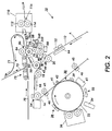
Figure 2 is an enlarged schematic side view of the transfer nips of
the printer of Figure 1;
Figure 3 is an enlarged cross-sectional schematic site view of the
cleaning station of figure 2;
Figure 4 is a graphical representation of residual toner as a
function of transfuse member temperature; and
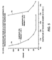
Figure 5 is a graphical representation of crease as a function of
transfuse member temperature for given representation of residual substrate
temperature.
DETAILED DESCRIPTION OF THE PREFERRED EMBODIMENTS
With reference to Figures 1 and 2, a multi-color cut sheet duplex
electrostatographic printer 10 has an intermediate transfer belt 12. The
intermediate transfer belt 12 is driven over guide rollers 14, 16, 18, and 20. The
intermediate transfer belt 12 moves in a process direction shown by the arrow A.
For purposes of discussion, the intermediate transfer member 12 defines a single
section of the intermediate transfer member 12 as a toner area. A toner area is
that part of the intermediate transfer member which receives the various
processes by the stations positioned around the intermediate transfer member
12. The intermediate transfer member 12 may have multiple toner areas;
however, each toner area is processed in the same way.
The toner area is moved past a set of four toner image producing
stations 22, 24, 26, and 28. Each toner image producing station 22, 24, 26, 28
operates to place a color toner image on the toner image of the intermediate
transfer member 12. Each toner image producing station 22, 24, 26, 28 operates
in the same manner to form developed toner image for transfer to the
intermediate transfer member 12.
The image producing stations 22, 24, 26, 28 are described in
terms of a photoreceptive system, but it is readily recognized by those of skilled
in the art that ionographic systems and other marking systems can readily be
employed to form developed toner images. Each toner image producing station
22, 24, 26, 28 has an image bearing member 30. The image bearing member 30
is a drum or belt supporting a photoreceptor.
The image bearing member 30 is uniformly charged at a charging
station 32. The charging station is of well-known construction, having charge
generation devices such as corotrons or scorotrons for distribution of an even
charge on the surface of the image bearing member 30. An exposure station 34
exposes the charged image bearing member 30 in an image-wise fashion to form
an electrostatic latent image at the image area. For purposes of discussion, the
image bearing member defines an image area. The image area is that part of
the image bearing member which receives the various processes by the stations
positioned around the image bearing member 30. The image bearing member
30 may have multiple image areas; however, each image area is processed in
the same way.
The exposure station 34 preferably has a laser emitting a
modulated laser beam. The exposure station 34 raster scans the modulated
laser beam onto the charged image area. The exposure station 34 can
alternately employ LED arrays or other arrangements known in the art to
generate a light image representation that is projected onto the image area of the
image bearing member 30. The exposure station 34 exposes a light image
representation of one color component of a composite color image onto the
image area to form a first electrostatic latent image. Each of the toner image
producing stations 22, 24, 26, 28 will form an electrostatic latent image
corresponding to a particular color component of a composite color image.
The image area is advanced to a development station 36. The
developer station 36 has a developer corresponding to the color component of
the composite color image. Typically, therefore, individual toner image producing
stations 22, 24, 26, and 28 will individually develop the cyan, magenta, yellow,
and black that make up a typical composite color image. Additional toner image
producing stations can be provided for additional or alternate colors including
highlight colors or other custom colors. Therefore, each of the toner image
producing stations 22, 24, 26, 28 develops a component toner image for transfer
to the toner area of the intermediate transfer member 12. The developer station
36 preferably develops the latent image with a charged dry toner powder to form
the developed component toner image. The developer can employ a magnetic
toner brush or other well known development arrangements.
The image area having the component toner image then advances
to the pretransfer station 38. The pretransfer station 38 preferably has a
pretransfer charging device to charge the component toner image and to achieve
some leveling of the surface voltage above the image bearing member 30 to
improve transfer of the component image from the image bearing member 30 to
the intermediate transfer member 12. Alternatively the pretransfer station 30 can
use a pretransfer light to level the surface voltage above the image bearing
member 30. Furthermore, this can be used in cooperation with a pretransfer
charging device. The image area then advances to a first transfer nip defined
between the image bearing member 30 and the intermediate transfer member
12. The image bearing member 30 and intermediate transfer member 12 are
synchronized such that each has substantially the same linear velocity at the first
transfer nip 40. The component toner image is electrostatically transferred from
the image bearing member 30 to the intermediate transfer member 12 by use of
a field generation station 42. The field generation station 42 is preferably a bias
roller that is electrically biased to create sufficient electrostatic fields of a polarity
opposite that of the component toner image to thereby transfer the component
toner image to the intermediate transfer member 12. Alternatively the field
generation station 42 can be a corona device or other various types of field
generation systems known in the art. A prenip transfer blade 44 mechanically
biases the intermediate transfer member 12 against the image bearing member
30 for improved transfer of the component toner image. The toner area of the
intermediate transfer member 12 having the component toner image from the
toner image producing station 22 then advances in the process direction.
After transfer of the component toner image, the image bearing
member 30 then continues to move the image area past a preclean station 39.
The preclean station employs a pre clean corotron to condition the toner charge
and the charge of the image bearing member 30 to enable improved cleaning of
the image area. The image area then further advances to a cleaning station 41.
The cleaning station 41 removes the residual toner or debris from the image
area. The cleaning station 41 preferably has blades to wipe the residual toner
particles from the image area. Alternately the cleaning station 41 can employ an
electrostatic brush cleaner or other well know cleaning systems. The operation
of the cleaning station 41 completes the toner image production for each of the
toner image producing stations 22, 24, 26, and 28.
The first component toner image is advanced at the image area
from the first transfer nip 40 of the image producing station 22 to the first transfer
nip 40 of the toner image producing station 24. Prior to entrance of the first
transfer nip 40 of the toner image producing station 24 an image conditioning
station 46 uniformly charges the component toner image to reduce stray, low or
oppositely charged toner that would result in back transfer of some of the first
component toner image to the subsequent toner image producing station 24.
The image conditioning stations, in particular the image conditioning station prior
to the first toner image producing station 22 also conditions the surface charge
on the intermediate transfer member 12. At each first transfer nip 40, the
subsequent component toner image is registered to the prior component toner
images to form a composite toner image after transfer of the final toner image by
the toner image producing station 28.
The geometry of the interface of the intermediate transfer member
12 with the image bearing member 30 has an important role in assuring good
transfer of the component toner image. The intermediate transfer member 12
should contact the surface of the image bearing member 30 prior to the region of
electrostatic field generation by the field generation station 42, preferably with
some amount of pressure to insure intimate contact. Generally, some amount of
pre-nip wrap of the intermediate transfer member 12 against the image bearing
member 30 is preferred. Alternatively, the pre-nip pressure blade 44 or other
mechanical biasing structure can be provided to create such intimate pre-nip
contact. This contact is an important factor in reducing high electrostatic fields
from forming at air gaps between the intermediate transfer member 12 and the
component toner image in the pre-nip region. For example, with a corotron as
the field generation station 42, the intermediate transfer member 12 should
preferably contact the toner image in the pre-nip region sufficiently prior to the
start of the corona beam profile. With a field generation station 42 of a bias
charging roller, the intermediate transfer member 12 should preferably contact
the toner image in the pre-nip region sufficiently prior to the contact nip of the
bias charging roller. "Sufficiently prior" for any field generation device can be
taken to mean prior to the region of the pre-nip where the field in any air gap
greater than about 50 µm between the intermediate transfer member 12 and the
component toner image has dropped below about 4 volts/micron due to falloff of
the field with pre-nip distance from the first transfer nip 40. The falloff of the field
is partly due to capacitance effects and this will depend on various factors. For
example, with a bias roller this falloff with distance will be slowest with larger
diameter bias rollers, and/or with higher resistivity bias rollers, and/or if the
capacitance per area of the insulating layers in the first transfer nip 40 is lowest.
Lateral conduction along the intermediate transfer member 12 can even further
extend the transfer field region in the pre-nip, depending on the transfer belt
resistivity and other physical factors. Using intermediate transfer members 12
having resistivity nearer the lower end of the preferred range discussed below
and/or systems that use large bias rollers, etc., preference is larger pre-nip
contact distances. Generally the desired pre-nip contact is between about 2 to
10 mm for resistivities within the desired range and with bias roller diameters
between about 12 mm and 50 mm.
The field generation station 42 will preferentially use very
conformable bias rollers for the first transfer nips 40 such as foam or other roller
materials having an effectively very low durometer ideally less than about 30
Shore A. In systems that use belts for the imaging modules, optionally the first
transfer nip 40 can include acoustic loosening of the component toner image to
assist transfer.
In the preferred arrangement, "slip transfer" is employed for
registration of the color image. For slip transfer, the contact zone between the
intermediate transfer member 12 and the image bearing member 30 will
preferably be minimized subject to the pre-nip restrictions. The post transfer
contact zone past the field generation station 42 is preferentially small for this
arrangement. Generally, the intermediate transfer member 12 can optionally
separate along the preferred bias roller of the field generation station 42 in the
post nip region if an appropriate structure is provided to insure that the bias roller
does not lift off the surface of the image bearing member due to the tension
forces of the intermediate transfer member 12. For slip transfer systems, the
pressure of the bias roller employed in the field generation station 42 should be
minimized. Minimized contact zone and pressure minimizes the frictional force
acting on the image bearing member 30 and this minimizes elastic stretch issues
of the intermediate transfer member 12 between first transfer nips 40 that can
degrade color registration. It will also minimize motion interactions between the
drive of the intermediate transfer member 12 and the drive of the image bearing
member 30.
For slip transfer systems, the resistivity of the intermediate transfer
member 12 should also be chosen to be high, generally within or even toward the
middle to upper limits of the most preferred range discussed later, so that the
required pre-nip contact distances can be minimized. In addition, the coefficient
of friction of the top surface material on the intermediate transfer member should
preferentially be minimized to increase operating latitude for the slip transfer
registration and motion quality approach.
In an alternate embodiment the image bearing members 30, such
as photoconductor drums, do not have separate drives and instead are driven by
the friction in the first transfer nips 40. In other words, the image bearing
members 30 are driven by the intermediate transfer member 12. Therefore, the
first transfer nip 40 imparts sufficient frictional force on the image bearing
member to overcome any drag created by the development station 36, cleaner
station 41, additional subsystems and by bearing loads. For a friction driven
image bearing member 30, the optimum transfer design considerations are
generally opposite to the slip transfer case. For example, the lead in of the
intermediate transfer member 12 to the first transfer zone preferentially can be
large to maximize the friction force due to the tension of the intermediate transfer
member 12. In the post transfer zone, the intermediate transfer member 12 is
wrapped along the image bearing member 30 to further increase the contact
zone and to therefore increase the frictional drive. Increased post-nip wrap has a
larger benefit than increased pre-nip wrap because there will be increased
pressure there due to electrostatic tacking forces. As another example, the
pressure applied by the field generation device 42 can further increase the
frictional force. Finally for such systems, the coefficient of friction of the material
of the top most layer on the intermediate transfer member 12 should
preferentially be higher to increase operating latitude.
The toner area then is moved to the subsequent first transfer nip
40. Between toner image producing stations are the image conditioning stations
46. The charge transfer in the first transfer nip 40 is normally at least partly due
to air breakdown, and this can result in non uniform charge patterns on the
intermediate transfer member 12 between the toner image producing stations 22,
24, 26, 28. As discussed later, the intermediate transfer member 12 can
optionally include insulating topmost layers, and in this case non uniform charge
will result in non uniform applied fields in the subsequent first transfer nips 40.
The effect accumulates as the intermediate transfer member 12 proceeds
through the subsequent first transfer nips 40. The image conditioning stations 46
"level" the charge patterns on the belt between the toner image producing
stations 22, 24, 26, 28 to improve the uniformity of the charge patterns on the
intermediate transfer member 12 prior to subsequent first transfer nips 40. The
image conditioning stations 46 are preferably scorotrons and alternatively can be
various types of corona devices. As previously discussed, the charge
conditioning stations 46 additionally are employed for conditioning the toner
charge to prevent re-transfer of the toner to the subsequent toner image
producing stations. The need for image conditioning stations 46 is reduced if the
intermediate transfer member 12 consists only of semiconductive layers that are
within the desired resistivity range discussed later. As further discussed later,
even if the intermediate transfer member 12 includes insulating layers, the need
for image conditioning stations 46 between the toner image producing stations
22, 24, 26, 28 is reduced if such insulating layers are sufficiently thin.
The guide roller 14 is preferably adjustable for tensioning the
intermediate transfer member 12. Additionally, the guide roller 14 can, in
combination with a sensor sensing the edge of the intermediate transfer member
12, provide active steering of the intermediate transfer member 12 to reduce
transverse wander of the intermediate transfer member 12 that would degrade
registration of the component toner images to form the composite toner image.
Each toner image producing station positions component toner
image on the toner area of the intermediate transfer member 12 to form a
completed composite toner image. The intermediate transfer member 12
transports the composite toner image from the last toner image producing station
28 to pre-transfer charge conditioning station 52. When the intermediate transfer
member 12 includes at least one insulating layer, the pretransfer charge
conditioning station 52 levels the charge at the toner area of the intermediate
transfer member 12. In addition the pre-transfer charge conditioning station 52 is
employed to condition the toner charge for transfer to a transfuse member 50. It
preferably is a scorotron and alternatively can be various types of corona
devices. A second transfer nip 48 is defined between the intermediate transfer
member 12 and the transfuse member 50. A field generation station 42 and pre-transfer
nip blade 44 engage the intermediate transfer member 12 adjacent the
second transfer nip 48 and perform the same functions as the field generation
stations and pre-transfer blades 44 adjacent the first transfer nips 40. However
the field generation station at the second transfer nip 48 can be relatively harder
to engage conformable transfuse members 50. The composite toner image is
transferred electrostatically and with heat assist to the transfuse member 50.
The electrical, characteristics of the intermediate transfer member
12 are also important. The intermediate transfer member 12 can optionally be
constructed of a single layer or multiple layers. In any case, preferably the
electrical properties of the intermediate transfer member 12 are selected to
reduce high voltage drops across the intermediate transfer member. To reduce
high voltage drops, the resistivity of the back layer of the intermediate transfer
member 12 preferably has sufficiently low resistivity. The electrical
characteristics and the transfer geometry must also be chosen to prevent high
electrostatic transfer fields in pre-nip regions of the first and second transfer nips
40, 48. High pre-nip fields at air gaps of around typically >50 microns between
the component toner images and the intermediate transfer member 12 can lead
to image distortion due to toner transfer across an air gap and can also lead to
image defects caused by pre-nip air breakdown. This can be avoided by bringing
the intermediate transfer member 12 into early contact with the component toner
image prior to the field generating station 42, as long as the resistivity of any of
the layers of the intermediate transfer member 12 are sufficiently high. The
intermediate transfer member 12 also should have sufficiently high resistivity for
the topmost layer to prevent very high current flow from occurring in the first and
second transfer nips 40, 48. Finally, the intermediate transfer member 12 and
the system design needs to minimize the effect of high and/or non-uniform
charge buildup that can occur on the intermediate transfer member 12 between
the first transfer nips 40.
The preferable material for a single layer intermediate transfer
member 12 is a semiconductive material having a "charge relaxation time" that is
comparable to or less than the dwell time between toner image producing
stations, and more preferred is a material having a "nip relaxation time"
comparable or less than the transfer nip dwell time. As used here, "relaxation
time" is the characteristic time for the voltage drop across the thickness of the
layer of the intermediate transfer member to decay. The dwell time is the time
that an elemental section of the transfer member 12 spends moving through a
given region. For example, the dwell time between imaging stations 22 and 24 is
the distance between imaging stations 22 and 24, divided by the process speed
of the transfer member 12. The transfer nip dwell time is the width of the contact
nip created during the influence of the field generation station 42, divided by the
process speed of the transfer member 12.
The "charge relaxation time" is the relaxation time when the
intermediate transfer member is substantially isolated from the influence of the
capacitance of other members within the transfer nips 40. Generally the charge
relaxation time applies for regions prior to or past the transfer nips 40. It is the
classic "RC time constant", that is ρkεo, the product of the material layer
quantities dielectric constant k times resistivity ρ times the permitivity of vacuum
εo. In general the resistivity of a material can be sensitive to the applied field in
the material. In this case, the resistivity should be determined at an applied field
corresponding to about 25 to 100 volts across the layer thickness. The "nip
relaxation time" is the relaxation time within regions such as the transfer nips 40.
If 42 is a corona field generation device, the "nip relaxation time" is substantially
the same as the charge relaxation time. However, if a bias transfer device is
used, the nip relaxation time is generally longer than the charge relaxation time.
This is because it is influenced not only by the capacitance of the intermediate
transfer member 12 itself, but it is also influenced by the extra capacitance per
unit area of any insulating layers that are present within the transfer nips 40. For
example, the capacitance per unit area of the photoconductor coating on the
image bearing member 30 and the capacitance per unit area of the toner image
influence the nip relaxation time. For discussion, CL represents the capacitance
per unit area of the layer of the intermediate transfer member 12 and Ctot
represents the total capacitance per unit area of all insulating layers in the first
transfer nips 40, other than the intermediate transfer member 12. When the field
generation station 42 is a bias roller, the nip relaxation time is the charge
relaxation time multiplied by the quantity [1 + (Ctot/ CL)].
The range of resistivity conditions defined in the above discussion
avoid high voltage drops across the intermediate transfer member 12 during the
transfers of the component toner images at the first transfer nips 40. To avoid
high pre-nip fields, the volume resistivity in the lateral or process direction of the
intermediate transfer member must not be too low. The requirement is that the
lateral relaxation time for charge flow between the field generation station 42 in
the first transfer nip 40 should be larger than the lead in dwell time for the first
transfer nip 40. The lead in dwell time is the quantity L/v. L is the distance from
the pre-nip region of initial contact of the intermediate transfer member 12 with
the component toner image, to the position of the start of the field generation
station 42 within the first transfer nip 40. The quantity v is the process speed.
The lateral relaxation time is proportional to the lateral resistance along the belt
between the field generating station 42 and the pre-nip region of initial contact,
and the total capacitance per area Ctot of the insulating layers in the first transfer
nip 40 between the intermediate transfer member 12 and the substrate of the
image bearing member 30 of the toner image producing station 22, 24, 26, 28. A
useful expression for estimating the preferred resistivity range that avoids
undesirable high pre-nip fields near the field generation stations 42 is: [ρLVLCtot]
> 1. The quantity is referred to as the "lateral resistivity" of the intermediate
transfer member 12. It is the volume resistivity of the member divided by the
thickness of the member. In cases where the electrical properties of the member
12 is not isotropic, the volume resistivity of interest for avoiding high pre-nip fields
is that resistivity of the layer in the process direction. Also, in cases where the
resistivity depends on the applied field, the lateral resistivity should be
determined at a field of between about 500 to 1500 volts/cm.
Thus the preferred range of resistivity for the single layer
intermediate transfer member 12 depends on many factors such as for example
the system geometry, the transfer member thickness, the process speed, and the
capacitance per unit area of the various materials in the first transfer nip 40. For
a wide range of typical system geometry and process speeds the preferred
resistivity for a single layer transfer belt is typically a volume resistivity less than
about 1013 ohm-cm and a more preferred range is typically <1011 ohm-cm volume
resistivity. The lower limit of preferred resistivity is typically a lateral resistivity
above about 108 ohms/square and more preferred is typically a lateral resistivity
above about 1010 ohms/square. As an example, with a typical intermediate
transfer member 12 thickness of around 0.01cm, a lateral resistivity greater than
1010 ohms/square corresponds to a volume resistivity of greater than 108 ohm-cm.
Discussion below will specify the preferred range of electrical
properties for the transfuse member 50 to allow good transfer in the second
transfer nip 48. The transfuse member 50 will preferably have multiple layers
and the electrical properties chosen for the topmost layer of the transfuse
member 50 will influence the preferred resistivity for the single layer intermediate
transfer member 12. The lower limits for the preferred resistivity of the single
layer intermediate transfer member 12 referred to above apply if the top most
surface layer of the transfuse member 50 has a sufficiently high resistivity,
typically equal to or above about 109 ohm-cm. If the top most surface layer of the
transfuse member 50 has a somewhat lower resistivity than about 109 ohm-cm,
the lower limit for the preferred resistivity of the single layer intermediate transfer
member 12 should be increased in order to avoid transfer problems in the
second transfer nip 48. Such problems include undesirably high current flow
between the intermediate transfer member 12 and the transfuse member 50, and
transfer degradation due to reduction of the transfer field. In the case where the
resistivity of the top most layer of the transfuse member 50 is less than about 109
ohm-cm, the preferred lower limit volume resistivity for the single layer
intermediate transfer member 12 will typically be around greater than or equal to
109 ohm-cm.
In addition, the intermediate transfer member 12 should have
sufficient lateral stiffness to avoid registration issues between toner image
producing stations 22, 24, 26, 28 due to elastic stretch. Stiffness is the sum of
the products of Young's modulus times the layer thickness for all of the layers of
the intermediate transfer member. The preferred range for the stiffness depends
on various systems parameters. The required value of the stiffness increases
with increasing amount of frictional drag at and/or between the toner image
producing stations 22, 24, 26, 28. The preferred stiffness also increases with
increasing length of the intermediate transfer member 12 between toner image
producing stations, and with increasing color registration requirements. The
stiffness is preferably >800 PSI-inches and more preferably >2000 PSI-inches.
A preferred material for the single layer intermediate transfer
member 12 is a polyamide that achieve good electrical control via conductivity
controlling additives.
The intermediate transfer member 12 may also optionally be multi-layered.
The back layer, opposite the toner area, will preferably be semi-conductive
in the discussed range. The preferred materials for the back layer of
a multi-layered intermediate transfer member 12 are the same as that discussed
for the single layer intermediate belt 12. Within limits, the top layers can
optionally be "insulating" or semiconductive. There are certain advantages and
disadvantages of either.
A layer on the intermediate transfer member 12 can be thought of
as behaving "insulating" for the purposes of discussion here if the relaxation time
for charge flow is much longer than the dwell time of interest. For example, a
layer behaves "insulating" during the dwell time in the first transfer nip 40 if the
nip relaxation time of that layer in the first transfer nip 40 is much longer than the
time that a section of the layer spends in traveling through the first transfer nip
40. A layer behaves insulating between toner image producing stations 22, 24,
26, 28 if the charge relaxation time for that layer is much longer than the dwell
time that a section of the layer takes to travel between the toner image
producing stations. On the other hand, a layer behaves semiconducting in the
sense meant here when the relaxation times are comparable or lower than the
appropriate dwell times. For example, a layer behaves semi conductive during
the dwell time of the first transfer nip 40 when the nip relaxation time is less than
the dwell time in the first transfer nip 40. Furthermore, a layer on the
intermediate transfer member 12 behaves semiconductive during the dwell time
between toner image producing stations 22, 24, 26, 28 if the relaxation time of
the layer is less than the dwell time between toner image producing stations.
The expressions for determining the relaxation times of any top layer on the
intermediate transfer member 12 are substantially the same as those described
previously for the single layer intermediate transfer member. Thus whether or
not a layer on the multi-layered intermediate transfer member 12 behaves
"insulating" or "semiconducting" during a particular dwell time of interest depends
not only on the electrical properties of the layer but also on the process speed,
the system geometry, and the layer thickness.
A layer of the transfer belt will typically behave "insulating" in most
transfer systems if the volume resistivity is generally greater than about 1013
ohm-cm. Insulating top layers on the intermediate transfer member 12 cause a
voltage drop across the layer and thus reduce the voltage drop across the
composite toner layer in the first transfer nip 40. Therefore, the presence of
insulating layers requires higher applied voltages in the first and second transfer
nips 40, 48 to create the same electrostatic fields operating on the charged
composite toner image. The voltage requirement is mainly driven by the
"dielectric thickness" of such insulating layers, which is the actual thickness of a
layer divided by the dielectric constant of that layer. One potential disadvantage
of an insulating layer is that undesirably very high voltages will be required on the
intermediate transfer member 12 for good electrostatic transfer of the component
toner image if the sum of the dielectric thickness of the insulating layers on the
intermediate transfer member 12 is too high. This is especially true in color
imaging systems with layers that behave "insulating" over the dwell time longer
than one revolution of the intermediate transfer member 12. Charge will build up
on such insulating top layers due to charge transfer in each of the field
generation stations 42. This charge buildup requires higher voltage on the back
of the intermediate transfer member 12 in the subsequent field generation
stations 42 to achieve good transfer of the subsequent component toner images.
This charge can not be fully neutralized between first transfer nips 40 with image
conditioning station 46 corona devices without also causing undesirable
neutralization or even reversal of the charge of the transferred composite toner
image on the intermediate transfer member 12. Therefore, to avoid the need for
unacceptably high voltages on the back of the intermediate transfer member 12,
the total dielectric thickness of such insulating top layers on the intermediate
transfer member 12 should preferably be kept small for good and stable transfer
performance. An acceptable total dielectric thickness can be as high as about 50
µm and a preferred value is <10 µm.
The top most layer of the intermediate transfer member 12
preferably has good toner releasing properties such as low surface energy, and
preferably has low affinity to oils such as silicone oils. Materials such as PFA,
TEFLON™, and various flouropolymers are examples of desirable overcoating
materials having good toner release properties. One advantage of an insulating
coating over the semiconductive backing layer of the intermediate transfer
member 12 is that such materials with good toner releasing properties are more
readily available if the constraint of needing them to also be semiconductive is
removed. Another potential advantage of high resistivity coatings applies to
embodiments that wish to use a transfuse member 50 having a low resistivity top
most layer, such as <<109 ohm-cm. As discussed, the resistivity for the
intermediate transfer member 12 of a single layer is preferably limited to typically
around >109 ohm-cm to avoid transfer problems in the second transfer nip 48 if
the resistivity of the top most layer of the transfuse member 50 is lower than
about 109 ohm-cm. For a multiple layer intermediate transfer member 12, having
a sufficiently high resistivity top most layer, preferably >109 ohm-cm, the
resistivity of the back layer can be lower.
Semiconductive coatings on the intermediate transfer member 12
are advantaged in that they do not require charge leveling to level the charge on
the intermediate transfer member 12 prior to and between toner image producing
stations 22, 24, 26, 28. Semiconductive coatings on the intermediate transfer
member are also advantaged in that much thicker top layers can be allowed
compared to insulating coatings. The charge relaxation conditions and the
corresponding ranges of resistivity conditions needed to enable such advantages
are similar to that already discussed for the back layer. Generally, the
semiconductive regime of interest is a resistivity such that the charge relaxation
time is smaller than the dwell time spent between toner image producing stations
22, 24, 26, 28. A more preferred resistivity construction allows thick layers, and
this construction is a resistivity range such that the nip relaxation time within the
first transfer nip 40 is smaller than the dwell time that a section of the
intermediate transfer member 12 takes to move through the first transfer nip 40.
In such a preferred regime of resistivity the voltage drop across the layer is small
at the end of the transfer nip dwell time, due to charge conduction through the
layer.
The constraint on the lower limit of the resistivity related to the
lateral resistivity apply to the semiconductive top most layer, to any
semiconductive middle layers, and to the semiconductive back layer of a multiple
layer intermediate transfer member 12. The preferred resistivity range for each
such layer is substantially the same as discussed for the single layer intermediate
transfer member 12. Also, the additional constraint on the resistivity related to
transfer problems in the second transfer nip 48 apply to the top most layer of a
multiple layer intermediate transfer member 12. Preferably, the top most
semiconductive layer of the intermediate transfer member 12 should be typically
>109 ohm-cm when the top most layer of the transfuse member 50 is typically
somewhat less than 109 ohm-cm.
Transfer of the composite toner image in the second transfer nip
48 is accomplished by a combination of electrostatic and heat assisted transfer.
The field generation station 42 and guide roller 74 are electrically biased to
electrostatically transfer the charged composite toner image from the
intermediate transfer member 12 to the transfuse member 50.
The transfer of the composite toner image at the second transfer
nip 48 can be heat assisted if the temperature of the transfuse member 50 is
maintained at a sufficiently high optimized level and the temperature of the
intermediate transfer member 12 is maintained at a considerably lower optimized
level prior to the second transfer nip 48. The mechanism for heat assisted
transfer is thought to be softening of the composite toner image during the dwell
time of contact of the toner in the second transfer nip 48. The toner softening
occurs due to contact with the higher temperature transfuse member 50. This
composite toner softening results in increased adhesion of the composite toner
image toward the transfuse member 50 at the interface between the composite
toner image and the transfuse member. This also results in increased cohesion
of the layered toner pile of the composite toner image. The temperature on the
intermediate transfer member 12 prior to the second transfer nip 48 needs to be
sufficiently low to avoid too high a toner softening and too high a resultant
adhesion of the toner to the intermediate transfer member 12. The temperature
of the transfuse member 50 should be considerably higher than the toner
softening point prior to the second transfer nip to insure optimum heat assist in
the second transfer nip 48. Further, the temperature of the intermediate transfer
member 12 just prior to the second transfer nip 48 should be considerably lower
than the temperature of the transfuse member 50 for optimum transfer in the
second transfer nip 48.
The temperature of the intermediate transfer member 12 prior to
the second transfer nip 48 is important for maintaining good transfer of the
composite toner image. An optimum elevated temperature for the intermediate
transfer member 12 can allow the desired softening of the composite toner image
needed to permit heat assist to the electrostatic transfer of the second transfer
nip 48 at lower temperatures on the transfuse member 50. However, there is a
risk of the temperature of the intermediate transfer member 12 becoming too
high so that too much softening of the composite toner image occurs on the
intermediate transfer member prior to the second transfer nip 48. This situation
can cause unacceptably high adhesion of the composite toner image to the
intermediate transfer member 12 with resultant degraded second transfer.
Preferably the temperature of the intermediate transfer member 12 is maintained
below or in the range of the Tg (glass transition temperature) of the toner prior to
the second transfer nip 48.
The transfuse member 50 is guided in a cyclical path by guide
rollers 74, 76, 78, 80. Guide rollers 74, 76 alone or together are preferably
heated to thereby heat the transfuse member 50. The intermediate transfer
member 12 and transfuse member 50 are preferably synchronized to have the
generally same velocity in the transfer nip 48. Additional heating of the transfuse
member is provided by a heating station 82. The heating station 82 is preferably
formed of infra-red lamps positioned internally to the path defined by the
transfuse member 50. Alternatively the heating station 82 can be a heated shoe
contacting the back of the transfuse member 50 or other heat sources located
internally or externally to the transfuse member 50. The transfuse member 50
and a pressure roller 84 define a third transfer nip 86 therebetween.
A releasing agent applicator 88 applies a controlled quantity of a
releasing material, such as a silicone oil to the surface of the transfuse member
50. The releasing agent serves to assist in release of the composite toner image
from the transfuse member 50 in the third transfer nip 86.
The transfuse member 50 is preferably constructed of multiple
layers. The transfuse member 50 must have appropriate electrical properties for
being able to generate high electrostatic fields in the second transfer nip 50. To
avoid the need for unacceptably high voltages, the transfuse member 50
preferably has electrical properties that enable sufficiently low voltage drop
across the transfuse member 50 in the second transfer nip 48. In addition the
transfuse member 50 will preferably ensure acceptably low current flow between
the intermediate transfer member 12 and the transfuse member 50. The
requirements for the transfuse member 50 depend on the chosen properties of
the intermediate transfer member 12. In other words, the transfuse member 50
and intermediate transfer member 12 together have sufficiently high resistance in
the second transfer nip 48.
The transfuse member 50 will preferably have a laterally stiff back
layer, a thick, conformable rubber intermediate layer, and a thin outer most layer.
Preferably the thickness of the back layer will be greater than about 0.05 mm.
Preferably the thickness of the intermediate conformable layers and the top most
layer together will be greater than 0.25 mm and more preferably will be greater
than about 1.0 mm. The back and intermediate layers need to have sufficiently
low resistivity to prevent the need for unacceptably high voltage requirements in
the second transfer zone 48. The preferred resistivity condition follows previous
discussions given for the intermediate transfer member 12. That is, the preferred
resistivity range for the back and intermediate layer of a multiple layer transfuse
member 50 insures that the nip relaxation time for these layers in the field
generation region of the second transfer nip 48 is smaller than the dwell time
spent in the field generation region of the second transfer nip 48. The
expressions for the nip relaxation times and the nip dwell time are substantially
the same as the ones discussed for the single layer intermediate transfer
member 12. Thus the specific preferred resistivity range for the back and
intermediate layers depends on the system geometry, the layer thickness, the
process speed, and the capacitance per unit area of the insulating layers within
the transfer nip 48. Generally, the volume resistivity of the back and intermediate
layers of the multi-layer transfuse member 50 will typically need to be below
about 1011 ohm-cm and more preferably will be below about 108 ohm-cm for most
systems. Optionally, the back layer of the transfuse member 50 can be highly
conductive such as a metal.
Similar to the multiple layer intermediate transfer member 12, the
top most layer of the transfuse member 50 can optionally behave "insulating"
during the dwell time in the transfer nip 48 (typically >1012 ohm-cm) or
semiconducting during the transfer nip 48 (typically 106 to 1012 ohm-cm).
However, if the top most layer behaves insulating, the dielectric thickness of such
a layer will preferably be sufficiently low to avoid the need for unacceptably high
voltages. Preferably for such insulating behaving top most layers, the dielectric
thickness of the insulating layer should typically be less than about 50µ and more
preferably will be less than about 10µ. If a very high resistivity insulating top
most layer is used, such that the charge relaxation time is greater than the
transfuse member cycle time, charge will build up on the transfuse member 50
due to charge transfer during the transfer nip 48. Therefore, a cyclic discharging
station 77 such as a scorotron or other charge generating device will be needed
to control the uniformity and reduce the level of cyclic charge buildup.
The transfuse member 50 can alternatively have additional
intermediate layers. Any such additional intermediate layers that have a high
dielectric thickness typically greater than about 10 microns will preferably have a
sufficiently low resistivity such to ensure low voltage drop across the additional
intermediate layers.
The transfuse member 50 preferably has a top most layer formed
of a material having a low surface energy, for example silicone elastomer,
fluoroelastomers such as Viton™, polytetrafluoroethylene, perfluoralkane, and
other fluorinated polymers. The transfuse member 50 will preferably have
intermediate layers between the top most and back layers constructed of a
Viton™ or silicone with carbon or other conductivity enhancing additives to
achieve the desired electrical properties. The back layer is preferably a fabric
modified to have the desired electrical properties. Alternatively the back layer
can be a metal such as stainless steel.
The transfuse member 50 can optionally be in the form of a
transfuse roller (not shown), or is preferably in the form of a transfuse belt. A
transfuse roller for the transfuse member 50 can be more compact than a
transfuse belt and it can also be advantaged relative to less complexity of the
drive and steering requirements needed to achieve good motion quality for color
systems. However, a transfuse belt has advantages over a transfuse roller such
as enabling large circumference for longer life, better substrate stripping
capability, and generally lower replacement costs.
The intermediate layer of the transfuse member 50 is preferably
thick to enable a high degree of conformance to rougher substrates 70 and to
thus expand the range of substrate latitude allowed for use in the printer 10. In
addition the use of a relatively thick intermediate layer, greater than about 0.25
mm and preferably greater than 1.0mm enables creep for improved stripping of
the document from the output of the third transfer nip 86. In a further
embodiment, thick low durometer conformable intermediate and top most layers
such as silicone are employed on the transfuse member 50 to enable creation of
low image gloss by the transfuse system with wide operating latitude.
The use of a relatively high temperature on the transfuse member
50 prior to the second transfer nip 48 creates advantages for the transfuse
system. The transfer step in the second transfer nip 48 simultaneously transfers
single and stacked multiple color toner layers of the composite toner image. The
toner layers nearest to the transfer belt interface will be hardest to transfer. A
given separation color toner layer can be nearest the surface of the intermediate
transfer member 12 or it can also be separated from the surface, depending on
the color toner layer to be transferred in any particular region. For example, if a
toner layer of magenta is the last stacked layer deposited onto the transfer belt,
the magenta layer can be directly against the surface of the intermediate transfer
member 12 in some color print regions or else stacked above cyan and/or yellow
toner layers in other color regions. If transfer efficiency is too low, a high fraction
of the color toners that are close to the intermediate transfer member 12 will not
transfer but a high fraction of the same color toner layers that are stacked onto
another color toner layer will transfer. Thus for example, if the transfer efficiency
of the composite toner image is not very high, the region of the composite toner
image having cyan toner directly in contact with the surface of the intermediate
transfer member 12 can transfer less of the cyan toner layer than the regions of
the composite toner image having cyan toner layers on top of yellow toner layers.
The transfer efficiency in the second transfer nip 48 is >95% therefore avoiding
significant color shift.
With reference to Figure 4 disclosing experimental data on the
amount of residual toner left on the intermediate transfer member 12 as a
function of the transfuse member 50 temperature. Curve 90 is with electric field,
pressure and heat assist and curve 92 is without electric field assist but with
pressure and heat assist. A very low amount of residual toner means very high
transfer efficiency. The toner used in the experiments has a glass transition
temperature range Tg of around 55°C. Substantial heat assist is observed at
temperatures of the transfuse member 50 above Tg. Substantially 100% toner
transfer occurs when operating with an applied field and with the transfuse
member 50 temperature above around 165°C, well above the range of the toner
Tg. Preferential temperatures will vary depending on toner properties. In
general, operation well above the Tg is found to be advantageous for the heat
assist to the electrostatic transfer for many different toners and system
conditions.
Too high a temperature of the transfuse member 50 in the second
transfer nip 48 can cause problems due to unacceptably high toner softening on
the intermediate transfer member side of the composite toner layer. Thus the
temperature of the transfuse member 50 prior to the second transfer nip 48 must
be controlled within an optimum range. The optimum temperature of the
composite toner image in the second transfer nip 48 is less than the optimum
temperature of the composite toner image in the third transfer nip 86. The
desired temperature of the transfuse member 50 for heat assist in the second
transfer nip 48 can be readily obtained while still obtaining the desired higher
toner temperatures needed for more complete toner melting in the third transfer
nip 86 by using pre-heating of the substrate 70. Transfer and fix to the substrate
70 is controlled by the interface temperature between the substrate and the
composite toner image. Thermal analysis shows that the interface temperature
increases with both increasing temperature of the substrate 70 and increasing
temperature of the transfuse member 50.
At a generally constant temperature of the transfuse member 50 in
the second and third transfer nips 48, 86, the optimum temperature for transfer in
the second transfer nip 48 is controlled by adjusting the temperature of the
intermediate transfer member 12, and transfuse in the third transfer nip 86 is
optimized by preheating of the substrate 70. Alternatively, for some toner
formulations or operation regimes no preheating of the substrate 70 is required.
The substrate 70 is transported and registered by a material feed
and registration system 69 into a substrate pre-heater 73. The substrate pre-heater
73 is preferably formed a transport belt transporting the substrate 70 over
a heated platen. Alternatively the substrate pre-heater 73 can be formed of
heated rollers forming a heating nip therebetween. The substrate 70 after
heating by the substrate preheater 73 is directed into the third transfer nip 86.
Figure 5 discloses experimental curves 94, 96 of a measure of fix
called crease as a function of the temperature of the transfuse member 50 for
different pre-heating temperatures of a substrate. Curve 94 is for a preheated
substrate and a curve 96 for a substrate at room temperature. The results
disclose that the temperature of the transfuse member 50 for similar fix level
decreases significantly at higher substrate pre-heating curve 94 compared to
lower substrate pre-heating curve 96. Heating of the substrate 70 by the
substrate pre-heater 73 prior to the third transfer nip 86 allows optimization of the
temperature of the transfuse member 50 for improved transfer of the composite
toner image in the second transfer nip 48. The temperature of the transfuse
member 50 can thus be controlled at the desired optimum temperature range for
optimum transfer in the second transfer nip 48 by controlling the temperature of
the substrate 70 at the corresponding required elevated temperature needed to
create good fix and transfer to the substrate 70 in the third transfer nip 86 at this
same controlled temperature of the transfuse member 50. Therefore cooling of
the transfuse member 50 prior to the second transfer nip 48 is not required for
optimum transfer in the second transfer nip 48. In other words the transfuse
member 50 can be maintained at substantially the same temperature in both the
second and third transfer nips 48, 86.
Furthermore, the over layer, the intermediate and topmost layers,
of the transfuse member 50 can be relatively thick, preferably greater than about
1.0mm, because no substantial cooling of the transfuse member 50 is required
prior to the second transfer nip 48. Relatively thick intermediate and topmost
layers of the transfuse member 50 allows for increased conformability. The
increased conformability of the transfuse member 50 permits printing to a wider
latitude of substrates 70 without a substantial degradation in print quality. In
other words the composite toner image can be transferred with high efficiency to
relatively rough substrates 70.
In addition, the transfuse member 50 is preferably at substantially
the same temperature in both the second and third transfer nips 48, 86.
However, the composite toner image preferably has a higher temperature in the
third transfer nip 86 relative to the temperature of the composite toner image in
the second transfer nip 48. Therefore the substrate 70 has a higher temperature
in the third transfer nip 86 relative to the temperature of the intermediate transfer
member 12 in the second transfer nip 48. Alternatively, the transfuse member 50
can be cooled prior to the second transfer nip 48, however the temperature of
the transfuse member 50 is maintained above, and preferably substantially
above the Tg of the composite toner image. Furthermore, under certain
operating conditions, the top surface of the transfuse member 50 can be heated
just prior to the second transfer nip 48.
The composite toner image is transferred and fused to the
substrate 70 in the third transfer nip 86 to form a completed document 72. Heat
in the third transfer nip 86 from the substrate 70 and transfuse member 50, in
combination with pressure applied by the pressure roller 84 acting against the
guide roller 76 transfer and fuse the composite toner image to the substrate 70.
The pressure in the third transfer nip 86 is preferably in the range of about 40 -
500 psi, and more preferably in the range 60 psi to 200 psi. The transfuse
member 50, by combination of the pressure in the third transfer nip 86 and the
appropriate durometer of the transfuse member 50 induces creep in the third
transfer nip to assist release of the composite toner image and substrate 70 from
the transfuse member 50. Preferred creep is greater than 4%. Stripping is
preferably further assisted by the positioning of the guide roller 78 relative to the
guide roller 76 and pressure roller 84. The guide roller 78 is positioned to form a
small amount of wrap of the transfuse member 50 on the pressure roller 84. The
geometry of the guide rollers 76, 78 and pressure roller 84 form the third transfer
nip 86 having a high pressure zone and an adjacent low pressure zone in the
process direction. The width of the low pressure zone is preferably one to three
times, or more preferably about two times the width of the high pressure zone.
The low pressure zone effectively adds an additional 2-3% creep and thereby
improves stripping. Additional stripping assistance can be provided by stripping
system 87, preferably an air puffing system. Alternatively the stripping system 87
can be a stripping blade or other well known systems to strip documents from a
roller or belt. Alternatively, the pressure roller can be substituted with other
pressure applicators such as a pressure belt.
After stripping, the document 72 is directed to a selectively
activatable glossing station 110 and thereafter to a sheet stacker or other well
know document handing system (not shown). The printer 10 can additionally
provide duplex printing by directing the document 72 through an inverter 71
where the document 72 is inverted and reintroduced to the pre-transfer heating
station 73 for printing on the opposite side of the document 72.
A cooling station 66 cools the intermediate transfer member 12
after second transfer nip 48 in the process direction. The cooling station 66
preferably transfers a portion of the heat on the intermediate transfer member 12
at the exit side of the second transfer nip 48 to a heating station 64 at the
entrance side of the second transfer nip 48. Alternatively the cooling station 66
can transfer a portion of the heat on the intermediate transfer member 12 at the
exit side of the second transfer nip 48 to the substrate prior to the third transfer
nip 86. Alternatively the heat sharing can be implemented with multiple heating
stations 64 and cooling stations 66 to improve heat transfer efficiency.
A cleaning station 54 engages the intermediate transfer member
12. The cleaning station 54 preferably removes oil that may be deposited onto
the intermediate transfer member 12 from the transfuse member 50 at the
second transfer nip. For example, if a preferred silicone top most layer is used
for the transfuse member 50, some silicone oil present in the silicone material
can transfer from the transfuse member 50 to the intermediate transfer member
12 and eventually contaminate the image bearing members 30. In addition the
cleaning station 54 removes residual toner remaining on the intermediate transfer
member 12. The cleaning station 54 also cleans oils deposited on the transfuse
member 50 by the release agent management system 88 that can contaminate
the image bearing members 30. The cleaning station 54 is preferably a cleaning
blade alone or in combination with an electrostatic brush cleaner, or a cleaning
web.
A cleaning station 58 (see figure 3) engages the surface of the
transfuse member 50 past the third transfer nip 86 to remove any residual toner
and contaminants from the surface of the transfuse member 50. The cleaning
system 58 includes a first cleaning roller 259 preferably formed of a metal tube or
cylinder. Partially melted toner forms a first toner layer on the outer surface of
the first cleaner roller 259. The partially melted first toner layer is adhesive or
sticky. The first cleaner roller 259 is oriented orthogonal to the process direction
of the transfuse member 50 and preferably extends across the substantially
entire width of the transfuse member 50. The first cleaner roller 259 is preferably
not driven, but is an idler roller deriving rotational motion from frictional
engagement of the first toner layer with the transfuse member 50.
The first cleaner roller 259 is held in pressure contact with the
surface of the transfuse member 50. The first cleaner roller 259 is preferably
positioned opposite guide roller 80. Alternatively a pressure roller 261 is
positioned opposite the first cleaner roller 259 to maintain adequate pressure
between the transfuse member 50 and first cleaner roller 259. The first cleaner
roller 259 rollingly engages the transfuse member 50 and applies a pressure of
10-50 psi to the transfuse member 50. A second cleaner roller 260 rollingly
engages the first cleaning roller 259. The second cleaning roller is also
preferably an idler roller deriving motion from friction contact with the first cleaner
roller. The first and second cleaner rollers define generally parallel axises of
rotation. A second toner layer coats the exterior surface of the second cleaner
roller 260. The first and second toner layers are in contact.
The second cleaner roller 260 is a tube or hollow cylinder defining
an interior reservoir 264. The second cleaner roller 260 is also cylindrical having
apertures 266 passing through the surface. The apertures 266 can be a series
of holes or a single spiral wound cut extending axially along the length of the
second cleaner roller 260. The apertures 266 allow excess toner of the second
toner layer to be squeezed or driven into the interior reservoir 264 of the second
cleaner roller 260 thereby maintaining the thickness of the second toner layer
263 on the surface of the second cleaner roller 260.
The first cleaner roller 259 is supported at a preestablished first
fixed distance from the surface of the transfuse member 50. The thickness of
the first toner layer 262 on the first cleaner roller 259 is effectively the
preestablished distance. Excess toner on the first toner layer of the first cleaner
roller 259 is transferred to the second toner layer on the second cleaner roller
260. Any excess second toner layer 263 on the second cleaner roller 260
squeezes through the apertures 266 into the interior reservoir 264 of the second
cleaner roller 260. The interior reservoir 261 of the second cleaner roller 260
operates as a reservoir for excess toner from the first and second cleaner rollers
259, 260.
The first and second cleaner rollers 259, 260 are initially each
coated with the first and second toner layers 262, 263. In operation of the
cleaning station 58, the rollers 259, 260 are heated until the first and second
toner layers 262, 263 are tacky or sticky. The first and second cleaner rolls can
be heated by the transfuse member 50 and additional heating can be provided
by a radiant cleaning heater 265. Toner particles and other particulates and
contaminants on the transfuse member 50 adhere to the sticky first toner layer
262 on the first cleaner roller 259. As the thickness of the first toner layer
increases from the accumulation of toner particles from the transfuse member
50, excess toner is transferred to the second toner layer 263 on the second
cleaner roller 260. The excess toner is squeezed into the interior reservoir 264 of
the second cleaner roller 260 by the pressure between the first and second
cleaner rollers 259, 260. The interior reservoir 264 of the second cleaner roller
260 extends the operational life of the cleaning system 58 between routine
service. The cleaner system 58 in most operational environments cleans the
transfuse member 50 in a single pass preparing the transfuse member so to
receive a new composite toner image.
The first and second cleaner roller 259, 260 are preferably formed
of a wear resistant, thermally conductive material such as steel, but can also be
brass, aluminum stainless steel, etc. The cleaning roller 259 is preferably heated
by the transfuse member 50 to thereby maintain the first toner layer 262 on the
first cleaning roller 259 in a partially melted state. The operating temperature
range of the first toner layer 262 is sufficiently high to melt the toner, typically
greater than 100° C. Too low a temperature of the toner layer results in the toner
failing to adhere to the first cleaning roller, or the toner to adhere to itself. The
temperature is also sufficiently low, generally less than 180° C, to prevent toner
layer splitting. The partially melted toner is maintained within the optimum
temperature range 100-180° C for cleaning by the temperature of the transfuse
member 50 in combination with additional heating provided by a cleaning heater
265 if required. The second toner layer 263 is preferably maintained in generally
the same temperature range as the first toner layer 262 by contact with the first
toner layer 262. Additional heating can be provided by additional cleaning
heaters, not shown.
The transfuse member 50 is driven in the cyclical path by the
pressure roller 84. Alternatively drive is provided or enhanced by driving guide
roller 74. The intermediate transfer member 12 is preferably driven by the
pressured contact with the transfuse member 50. Drive to the intermediate
transfer member 12 is preferably derived from the drive for the transfuse member
50, by making use of adherent contact between intermediate transfer member 12
and the transfuse member 50. The adherent contact causes the transfuse
member 50 and intermediate transfer member 12 to move in synchronism with
each other in the second transfer nip 48. Adherent contact between the
intermediate transfer member 12 and the toner image producing stations 22, 24,
26, 28 may be used to ensure that the intermediate transfer member 12 moves in
synchronism with the toner image producing stations 22, 24, 26, 28 in the first
transfer zones 40. Therefore the toner image producing stations 22, 24, 26, 28
can be driven by the transfuse member 50 via the intermediate transfer member
12. Alternatively, the intermediate transfer member 12 is independently driven.
When the intermediate transfer member is independently driven, a motion buffer
(not shown) engaging the intermediate transfer member 12 buffers relative
motion between the intermediate transfer member 12 and the transfuse member
50. The motion buffer system can include a tension system with a feedback and
control system to maintain good motion of the intermediate transfer member 12
at the first transfer nips 40 independent of motion irregularity translated to the
intermediate transfer member 12 at the second transfer nip 48. The feedback
and control system can include registration sensors sensing motion of the
intermediate transfer member 12 and/or sensing motion of the transfuse member
50 to enable registration timing of the transfer of the composite toner image to
the substrate 70.
A gloss enhancing station 110 is preferably positioned down
stream in the process direction from the third transfer nip 86 for selectively
enhancing the gloss properties of documents 72. The gloss enhancing station
110 has opposed fusing members 112, 114 defining a gloss nip 116 there
between. The gloss nip 116 is adjustable to provide the selectability of the gloss
enhancing. In particular, the fusing members are cammed whereby the transfuse
nip is sufficiently large to allow a document to pass through with out substantial
contact with either fusing member 112, 114 that would cause glossing. When
the operator selects gloss enhancement, the fusing members 112, 114 are
cammed into pressure relation and driven to thereby enhancement the level of
gloss on documents 72 passed through the gloss nip 116. The amount of gloss
enhancement is operator selectable by adjustment of the temperature of the
fusing members 112, 114. Higher temperatures of the fusing members 112, 114
will result in increased gloss enhancement. United States Patent 5,521,688,
Hybrid Color Fuser, incorporated herein by reference, describes a gloss
enhancing station with a radiant fuser.
The separation of fixing and glossing functions provides
operational advantages. Separation of the fixing and glossing functions permits
operator selection of the preferred level of gloss on the document 72. The
achievement of high gloss performance for color systems generally requires
relatively higher temperatures in the third transfer nip 86. It also typically requires
materials on the transfuse member 50 having a higher heat and wear resistance
such as Viton™ to avoid wear issues that result in differential gloss caused by
changes in surface roughness of the transfuse member due to wear. The higher
temperature requirements and the use of more heat and wear resistant materials
generally result in the need for high oil application rates by the release agent
management system 88. In transfuse systems such as the printer 10 increased
temperatures and increased amounts of oil on the transfuse member 50 could
possibly create contamination problems of the photoreceptors 30. Printers
having a transfuse system and needing high gloss use a thick nonconformable
transfuse member, or a relatively thin transfuse member. However, a relatively
nonconformable transfuse member and a relatively thin transfuse member fail to
have the high degree of conformance needed for good printing on, for example,
rougher paper stock.
The use of the gloss enhancing station 110 substantially reduces
or eliminates the need for gloss creation in the third transfer nip 86. The
reduction or elimination of the need for gloss in the third transfer nip 86 therefore
minimizes surface wear issues for color transfuse member materials and enables
a high life transfuse member 50 with readily available silicone or other similar soft
transfuse member materials. It allows the use of relatively thick layers on the
transfuse member 50 with resultant gain in operating life for the transfuse
member materials and with resultant high conformance for imaging onto rougher
substrates. It reduces the temperature requirements for the transfuse materials
set with further gain in transfuse material life, and it can substantially reduce the
oil requirements in the third transfer nip 86.
The gloss enhancing station 110 is preferably positioned
sufficiently close to the third transfer nip 86, so the gloss enhancing station 110
can utilize the increased document temperature that occurs in the third transfer
nip 86. The increased temperature of the document 72 reduces the operating
temperature needed for the gloss enhancing station 110. The reduced
temperature of the gloss enhancing station 110 improves the life and reliability of
the gloss enhancing materials.
Use of a highly conformable silicone transfuse member 50 is an
example demonstrated as one important means for achieving good operating fix
latitude with low gloss. Critical parameters are sufficiently low durometer for the
top most layer of the transfuse member 50, preferably of rubber, and relatively
high thickness for the intermediate layers of the transfuse member 50, preferably
also of rubber. Preferred durometer ranges will depend on the thickness of the
composite toner layer and the thickness of the transfuse member 50. The
preferred range will be about 25 to 55 Shore A, with a general preference for
about 35 to 45 Shore A range. Therefore preferred materials include many
silicone material formulations. Thickness ranges of the over layer of the
transfuse member 50 will preferably be greater than about 0.25 mm and more
preferably greater than 1.0 mm. Preference relative to low gloss will be for
generally thicker layers to enable extended toner release life, conformance to
rough substrates, extended nip dwell time, and improved document stripping. In
an optional embodiment a small degree of surface roughness is introduced on
the surface of the transfuse member 50 to enhance the range of allowed
transfuse material stiffness for producing low transfuse gloss. Especially with
higher durometer materials and/or low thickness layers there will be a tendency
to reproduce the surface texture of the transfuse member. Thus some surface
roughness of the transfuse member 50 will tend toward low gloss in spite of high
stiffness. Preference will be transfuse member surface gloss number <30 GU.
A narrow operating temperature latitude for good fix with low gloss
in transfuse has been demonstrated at relatively high toner mass/area
conditions. Toner of size about 7 microns requiring toner masses about 1
mg/cm2 requires a temperature of the transfuse member 50 between 110-120C
and preheating of the paper to about 85C to achieve gloss levels of <30 GU
while simultaneously achieving acceptable crease level below 40. However, low
mass/area toner conditions have shown increased operating transfuse system
temperature range for fix and low gloss. The use of small toner having high
pigment loading, in combination with a conformable transfuse member 50, allows
low toner mass/area for color systems therefore extending the operating
temperature latitude for low gloss in the third transfer nip 86. Toner of size about
3 microns requiring toner masses about 0.4 mg/cm2 requires a temperature of
the transfuse member 50 between 110-150C, and paper preheating to about
85C, to achieve gloss levels of <30 GU while simultaneously achieving
acceptable crease level below 40.
The gloss enhancing station 110 preferably has fusing members
112, 114 of Viton™. Alternatively hard fusing members such as thin and thick
Teflon™ sleeves/overcoatings on rigid rollers or on belts, or else such
overcoatings over rubber underlayers, are alternative options for post transfuse
gloss enhancing. The fusing members 112, 114, preferably have an top most
fixing layer stiffer than that used for the top most layer of the transfuse member
50, with a high level of surface smoothness (surface gloss preferably > 50 GU
and more preferably >70 GU). The topmost surface can be alternatively textured
to provide a texture to the documents 72. The gloss enhancing station 110
preferably includes a release agent management application system (not shown).
The gloss enhancing station can further include stripping mechanisms such as
an air puffer to assist stripping of the document 72 from the fusing members 112,
114.
Optionally the toner formulation may include wax to reduce the oil
requirements for the gloss enhancing station 110.
The gloss enhancing station 110 is described in combination with
the printer 10 having an intermediate transfer member 12 and a transfuse
member 50. However, the gloss enhancing station 110 is applicable with all
printers having transfuse systems producing documents 72 with low gloss. In
particular this can include transfuse systems that employ a single
transfer/transfuse member.
As a system example, the transfuse member 50 is preferably 120
C in the third transfer nip 86, and the substrate 70 is preheated to 85 C. The
result is a document 72 having a gloss value 20-30 GU. The fusing members are
preferably heated to 120C. The temperature of the fusing members 112, 114 is
preferably adjustable so different degrees or levels of glossing can be applied to
different print runs dependent on operator choice. Higher temperatures of the
fusing members 112, 114 increase the gloss enhancement while lower
temperatures will the reduce the amount of gloss enhancement on the
documents 72.
The fusing members 112, 114 are preferably fusing rollers, but
can alternatively the fusing members 112, 114 can be fusing belts. The top most
surface of each fusing member 112, 114 is relatively non-conformable, preferably
having a durometer above 55 Shore A. The gloss enhancing station 110
provides gloss enhancing past the printer 10 employing a transfuse system that
operates with low gloss in the third transfer nip 86. The printer 10 preferably
forms documents 72 having 10-30 Gardner Gloss Units (GU) after the third
transfer nip 86. The gloss on the documents 72 will vary with toner mass per unit
area. The gloss enhancing unit 110 preferably increases the gloss of the
documents 72 to greater than about 50 GU on Lustro Gloss™ paper distributed
by SD Warren Company.