EP1072946B1 - Schneidevorrichtung für blattförmiges gefördertes Material in einem fotografischen Behandlungsgerät - Google Patents
Schneidevorrichtung für blattförmiges gefördertes Material in einem fotografischen Behandlungsgerät Download PDFInfo
- Publication number
- EP1072946B1 EP1072946B1 EP20000116312 EP00116312A EP1072946B1 EP 1072946 B1 EP1072946 B1 EP 1072946B1 EP 20000116312 EP20000116312 EP 20000116312 EP 00116312 A EP00116312 A EP 00116312A EP 1072946 B1 EP1072946 B1 EP 1072946B1
- Authority
- EP
- European Patent Office
- Prior art keywords
- slit
- sheet
- conveyed material
- movable member
- conveyed
- Prior art date
- Legal status (The legal status is an assumption and is not a legal conclusion. Google has not performed a legal analysis and makes no representation as to the accuracy of the status listed.)
- Expired - Lifetime
Links
Images


Classifications
-
- G—PHYSICS
- G03—PHOTOGRAPHY; CINEMATOGRAPHY; ANALOGOUS TECHNIQUES USING WAVES OTHER THAN OPTICAL WAVES; ELECTROGRAPHY; HOLOGRAPHY
- G03B—APPARATUS OR ARRANGEMENTS FOR TAKING PHOTOGRAPHS OR FOR PROJECTING OR VIEWING THEM; APPARATUS OR ARRANGEMENTS EMPLOYING ANALOGOUS TECHNIQUES USING WAVES OTHER THAN OPTICAL WAVES; ACCESSORIES THEREFOR
- G03B27/00—Photographic printing apparatus
- G03B27/32—Projection printing apparatus, e.g. enlarger, copying camera
- G03B27/52—Details
- G03B27/58—Baseboards, masking frames, or other holders for the sensitive material
- G03B27/587—Handling photosensitive webs
- G03B27/588—Supply rolls; Cutting arrangements
-
- Y—GENERAL TAGGING OF NEW TECHNOLOGICAL DEVELOPMENTS; GENERAL TAGGING OF CROSS-SECTIONAL TECHNOLOGIES SPANNING OVER SEVERAL SECTIONS OF THE IPC; TECHNICAL SUBJECTS COVERED BY FORMER USPC CROSS-REFERENCE ART COLLECTIONS [XRACs] AND DIGESTS
- Y10—TECHNICAL SUBJECTS COVERED BY FORMER USPC
- Y10T—TECHNICAL SUBJECTS COVERED BY FORMER US CLASSIFICATION
- Y10T83/00—Cutting
- Y10T83/727—With means to guide moving work
- Y10T83/73—Guide fixed to or integral with stationary tool element
-
- Y—GENERAL TAGGING OF NEW TECHNOLOGICAL DEVELOPMENTS; GENERAL TAGGING OF CROSS-SECTIONAL TECHNOLOGIES SPANNING OVER SEVERAL SECTIONS OF THE IPC; TECHNICAL SUBJECTS COVERED BY FORMER USPC CROSS-REFERENCE ART COLLECTIONS [XRACs] AND DIGESTS
- Y10—TECHNICAL SUBJECTS COVERED BY FORMER USPC
- Y10T—TECHNICAL SUBJECTS COVERED BY FORMER US CLASSIFICATION
- Y10T83/00—Cutting
- Y10T83/869—Means to drive or to guide tool
- Y10T83/8821—With simple rectilinear reciprocating motion only
- Y10T83/8822—Edge-to-edge of sheet or web [e.g., traveling cutter]
-
- Y—GENERAL TAGGING OF NEW TECHNOLOGICAL DEVELOPMENTS; GENERAL TAGGING OF CROSS-SECTIONAL TECHNOLOGIES SPANNING OVER SEVERAL SECTIONS OF THE IPC; TECHNICAL SUBJECTS COVERED BY FORMER USPC CROSS-REFERENCE ART COLLECTIONS [XRACs] AND DIGESTS
- Y10—TECHNICAL SUBJECTS COVERED BY FORMER USPC
- Y10T—TECHNICAL SUBJECTS COVERED BY FORMER US CLASSIFICATION
- Y10T83/00—Cutting
- Y10T83/889—Tool with either work holder or means to hold work supply
- Y10T83/896—Rotatable wound package supply
- Y10T83/902—Plural supply sources
Definitions
- the present invention relates to a cutting mechanism for sheet-like conveyed materials for cutting the long sheet-like conveyed material widthwisely thereof which is conveyed along a transfer path in an apparatus. It also relates to a photographic processing apparatus.
- a long sheet-like material or a photosensitive material is supplied from its roll stored in a magazine, cut to a desired length, exposed in the exposure processing unit, developed in the development processing unit, dried in the drying unit, and released as photographs.
- the transfer units for conveying the photosensitive material are positioned so as to communicate the magazine with the exposure processing unit, the development processing unit, and the drying unit.
- the exposure processing unit, the development processing unit, the drying unit, and the transfer unit are separately provided as independent unit mechanisms for ease of assembly and disassembly.
- the transfer units are installed at various positions in the apparatus and provided as multiple units. Some of the transfer units are arranged withdrawable out from the apparatus body for ease of maintenance.
- any conventional photographic processing apparatus if the sheet-like conveyed material is jammed on the transfer path by a possible fault, it has to be cut apart by scissors or a cutter knife manually inserted into the apparatus and elaborately accessed to the location of jamming between the units. Then, the relevant unit is unlocked and removed out from the apparatus and a jammed portion of the sheet-like conveyed material is taken out from the unit.
- Such a troublesome task is generally conducted at a limited narrow space in the apparatus body, hence declining the operability, consuming the time, and discouraging the safety due to the use of scissors or a cutter knife.
- the cutting mechanism for sheet-like conveyed material according to the present invention is provided with the features defined by claim 1.
- the cutting mechanism for sheet-like conveyed material permits the blade mounted to the movable member to travel in the crosswise direction of the transfer path when the movable member is moved relative to the unit. Accordingly, the sheet-like conveyed material halted and maintained on the transfer path can be cut apart widthwisely by the blade traveling in the crosswise direction of the transfer path. The sheet-like conveyed material jammed on the transfer path will thus be liberated readily and easily.
- the movable member may preferably comprise a pair of strips arranged opposite to each other on both sides of the transfer path while the blade is disposed between the two strips.
- This arrangement permits the sheet-like conveyed material to run between the two opposite strips. In case that the sheet-like conveyed material is jammed on the transfer path, it can simply be cut apart by advancing the movable member with the blade mounted between the two strips thereof.
- the two strips may preferably be deflected outwardly as spaced increasingly from each other at the upstream end of the transfer path side.
- This arrangement of the cutting mechanism for sheet-like conveyed material allows the sheet-like conveyed material, for example, of which the leading end is slightly skewed as forwarded from the upstream, to be positively guided by the deflected ends of the two strips so as to run between the two strips. Thereby, the sheet-like conveyed material can successfully be conveyed without major interruption.
- the cutting mechanism may further comprise a holding means for restricting the forward and backward movement of the movable member in relative to the unit and maintaining the movable member at a given location.
- This arrangement eliminates undesired movements of the movable member and can ensure the smooth conveying of the sheet-like conveyed material without major interruption.
- the movable member may preferably comprise a through slit provided member which is arranged for moving in a direction widthwisely of the sheet-like conveyed material and has a through slit provided therein through which the sheet-like conveyed material is conveyed along the transfer path, and a blade provided at one end of the through slit thereof along the widthwise direction of the sheet-like conveyed material, wherein the sheet-like conveyed material extending across the through slit can be cut apart with the blade as the through slit member is moved from one position to the other.
- This arrangement permits the photosensitive material which is jammed in one of two adjacent units to be cut apart with the blade provided at one end of the through slit when the through slit provided member is moved towards the other end widthwisely of the photosensitive material which remains extending across the through slit in the through slit provided member after the photographic processing action is canceled. Accordingly, a jammed portion of the photosensitive material can be taken out from the unit by an operator of the apparatus.
- the blade is provided at the one end of the through slit in the through slit provided member and will rarely be interrupted with any other components than the photosensitive material. As a result, a cover for protecting the blade from being interrupted is unnecessary. Since the blade in the cutting mechanism for maintenance task is interrupted by no other components but the photosensitive material, the entire arrangement of the cutting mechanism can be simplified.
- the cutting mechanism for sheet-like conveyed material may further comprise an urging means for urging the through slit provided member in a direction opposite to the direction for cutting the sheet-like conveyed material, and a positioning means for positioning the through slit provided member so that the sheet-like conveyed material is conveyed across the through slit of the through slit provided member, the positioning means having a stopper thereof for halting the movement of the through slit provided member driven by the urging force of the urging means.
- This arrangement allows the through slit provided member to be returned back to its original position by the yielding force of the urging means after the cutting action and held at the position with the stopper so that the photosensitive material can pass across its through slit. Accordingly, the positioning of the through slit provided member or the positioning for allowing the photosensitive material to pass across the through slit in the through slit provided member will be conducted easily and certainly.
- the urging means may preferably be a coil spring while the through slit provided member is a portion of the coil spring.
- This arrangement can make a combination of the urging means and the through slit provided member more simple.
- a photographic processing apparatus comprising at least two or more units, each having a transfer path for conveying a long sheet-like conveyed material or a photosensitive material in the lengthwise direction, the units aligned in the apparatus body with their transfer paths connecting one another, at least one of the units arranged withdrawable out from the apparatus body in a crosswise direction of the transfer path.
- a movable member is accommodated in the withdrawable unit for moving forward and backward in the crosswise direction of the transfer path.
- the movable member includes a blade for cutting the photosensitive material as the movable member is moved.
- This arrangement permits the photosensitive material, when it is jammed, to be cut apart by the movable member simply moved widthwisely of the photosensitive material with no use of scissors or the like inserted and accessed to the location of jamming in the apparatus. More particularly, in case that the photosensitive material is jammed and halted between the two units to interrupt the relative action of the two units, it can be cut apart hence allowing the relevant unit to be withdrawn from the apparatus. A jammed portion of the photosensitive material will then be taken out from the unit readily and easily.
- Another photographic processing apparatus comprising: at least two or more magazines disposed in the apparatus body, each magazine arranged in which a roll of photosensitive material is stored as a long sheet-like conveyed material; a transfer path disposed in the apparatus body and arranged to communicate with the feed outlet of each magazine and combine its branches to one path at the downstream; and a transfer unit disposed in the apparatus body and arranged to selectively convey one of at least two or more sheets of the photosensitive material along the transfer path.
- the transfer unit has movable members disposed therein, each movable member arranged opposite to the feed outlet of the corresponding magazine for moving forward and backward in a crosswise direction of the transfer path.
- the movable member includes a blade for cutting the photosensitive material widthwisely thereof as the movable member is moved.
- This arrangement permits the movable member to be withdrawn when the photosensitive material is jammed while conveyed from the magazine to the transfer unit. After the photosensitive material is cut apart between the magazine and the unit, the unit is removed out from the apparatus body. Finally, a jammed portion of the photosensitive material is taken out from the unit which has been removed out from the apparatus body.
- Fig. 1 is a schematic perspective view of the photographic processing apparatus of one embodiment.
- the photographic processing apparatus body 1 comprises an exposure module 2 for cutting a roll of photosensitive material (a conveyed sheet material) to pieces of a predetermined length and projecting images recorded on a photography film onto the photosensitive material pieces for exposure, a development processing module 8 for subjecting the exposed photosensitive material pieces to a development process, a drying process unit 9 for drying the developed photosensitive material pieces, and a sorting unit 11 for sorting the dried photosensitive material pieces in a given order.
- an exposure module 2 for cutting a roll of photosensitive material (a conveyed sheet material) to pieces of a predetermined length and projecting images recorded on a photography film onto the photosensitive material pieces for exposure
- a development processing module 8 for subjecting the exposed photosensitive material pieces to a development process
- a drying process unit 9 for drying the developed photosensitive material pieces
- a sorting unit 11 for sorting the dried photosensitive material pieces in a given order.
- the exposure processing module 2 includes an exposure unit for exposing each photosensitive material piece positioned on its exposure stage and a transfer unit for conveying the photosensitive material from a magazine to the exposure stage which all are accommodated inside covers 2a.
- a lens unit is provided orthogonal to the photosensitive material piece positioned on the exposure state so that light emitted from a light source 3 is reflected on a mirror tunnel 4, passed through the image on the film held in a film mask 5, and projected onto the lens unit.
- a monitor 6 is mounted on the exposure processing module for displaying the image scanned by a scanner unit.
- the development processing module 8 conducts development, bleaching, fixing and stabilization of the exposed photosensitive material. It incorporates a dark room for preventing the exposure to any stray light from the outside.
- the development unit consists of a development tank, a fixing tank, and a stabilizing tank aligned along the direction of conveying of the photosensitive material.
- a transfer unit is provided including transfer rollers and conveying belts.
- the drying processing unit 9 is provided for drying the developed photosensitive material and includes a blower for blowing hot air to the photosensitive material being conveyed.
- the drying unit 9 extends upwardly of the apparatus for discharging the dried photosensitive material from its outlet 10 located at the top.
- the sorting unit 11 comprises a first transfer unit 12 for conveying the photosensitive material discharged from the outlet 10 in the X direction oriented at substantially a right angle to the conveying direction, a second transfer unit 16 provided adjacent to the downstream end 12a of the first transfer unit 12 for conveying the photosensitive material received from the first transfer unit 12 in the Y direction oriented substantially in parallel with the conveying direction in the apparatus, and a contact plate 19 provided opposite to the first transfer unit 12, both sandwiching the second transfer unit 16.
- the contact plate 19 is a planar strip anchored to the apparatus body 1 for halting the photosensitive material released out from the downstream end 12a of the first transfer unit 12 and dropping the same on the second transfer unit 16.
- Fig. 2 is a schematic cross sectional internal view of the exposure processing module 2 of the photographic processing apparatus shown in Fig. 1.
- Fig. 3 is a schematic perspective internal view of the exposure processing module 2 of the photographic processing apparatus shown in Fig. 1. More specifically, components and their arrangement are shown in cross section with the covers 2a removed.
- the exposure processing module 2 according to the present invention includes a photosensitive material supplying means for supplying the photosensitive material P as well as the second transfer unit 40 for conveying the photosensitive material P to the exposure stage (not shown) .
- the photosensitive material supplying means comprises a magazine 21 (a combination of a first magazine 21A and a second magazine 21B) in which the photosensitive material P is stored in a roll and the first transfer unit 30 for conveying the photosensitive material P to the second transfer unit 40 at the downstream.
- a roll of the photosensitive material P is sandwiched between and conveyed by a pair of magazine rollers 22, 22.
- the magazine 21 is formed of a box-like shape having a feed outlet 23 (an opening at the downstream of the magazine rollers 22, 22) for feeding out the photosensitive material P.
- the first transfer unit 30 is installed so that it can be drawn out from the apparatus body 1 crosswisely of the conveying direction. More particularly, while a stationary rail 27 is provided in the apparatus body 1, the first transfer unit 30 has a first slide rail 28 and a second slide rail 29 disposed corresponding to the shape and the location of the stationary rail 27 (as shown in Fig. 3, the first transfer unit 30 can be traveled to and from the apparatus body 1 with its first 28 and second slide rail 29 running on the stationary rail 27).
- the first transfer unit 30 also contains transfer sections consisting mainly of advancing rollers 31 and pressing rollers 32, a cutter 33 for cutting widthwisely the photosensitive material P, a guide roller 34 for guiding the traveling of the photosensitive material P, and a guide plate 35 for guiding the photosensitive material P from the advancing roller 31 to the guide roller 34.
- the advancing roller 31 (a first advancing roller 31A or a second advancing roller 31B) is arranged for withdrawing the photosensitive material P a given length from the magazine 21A or 21B while the pressing rollers 32 (a first set of pressing rollers 32A or a second set of pressing rollers 32B) are disposed for conveying the photosensitive material P which is sandwiched between the advancing roller 31 and the pressing rollers 32.
- the two roller transfer sections in the first transfer unit 30 are disposed close to each other for best utilizing the space defined by the covers 2a in the exposure processing module 2.
- Each the transfer roller section accompanied with the magazine 21 is located opposite to the feed outlet 23 of the magazine 21.
- the magazines 21 are provided on both sides of the first transfer unit 30 with the feeding direction of the photosensitive material P from each magazine 21 matching the conveying direction across the first transfer unit 30. More specifically, the photosensitive material P is released substantially in the horizontal direction from the first magazine 21A while substantially in the vertical direction from the second magazine 21B.
- the arrows denote the conveying directions of the photosensitive material P in the magazines 21A and 21B as well as in the second transfer unit 40.
- the first transfer unit 30 there is a conveying path Q which is a part of the transfer path of the photosensitive material P for photographic processing, where the photosensitive materials P released from the feed outlets 23 of the two magazines 21 are conveyed after combined at the junction (at point 0) .
- Each photosensitive material P is passed between the advancing roller 31 and the pressing rollers 32 over the guide plate 35 and conveyed via the guide roller 34 to the second transfer unit 40 before transferred to the exposure stage as described.
- Fig. 4 illustrates an enlarged view of the first transfer unit 30 of Fig. 2.
- the pressing rollers 32A and 32B paired with the advancing rollers 31A and 31B respectively are anchored to the corresponding positions to the advancing rollers 31A and 31B in the first transfer unit 30 by locking mechanisms, namely snap locks 36 (a first snap lock 36A and a second snap lock 36B).
- the advancing roller 31 is secured to the pressing rollers 32 by the snap lock 36 so that the photosensitive material P can successfully be conveyed between the advancing roller 31 and the pressing rollers 32.
- the snap lock 36 is located at an appropriate position in the front end (behind the covers 2a) of the first transfer unit 30 so as not to interrupt the action of the advancing roller 31.
- the photosensitive material P supplied from the first magazine 21A is introduced through a first entrance guide 37A and passed between the advancing roller 31A and the pressing rollers 32A as running along a first sub transfer path Q1 via a first advancing roller guide 38A and a first guide 35a of the guide plate 35 to the guide roller 34. Then, the photosensitive material P is passed through a pre-cutter guide 39 along the transfer path Q and further conveyed along the path after the cutter 33.
- the feed (a length) of the photosensitive material P supplied from the first magazine 21A is determined by the number of revolutions (a pulse signal) of the first advancing roller 31A.
- the action of the cutter 33 is thus controlled by the pulse signal to cut the photosensitive material P to a desired length.
- the photosensitive material P supplied from the second magazine 21B is introduced through a second entrance guide 37B and passed between the advancing roller 31B and the pressing rollers 32B as running along a second sub transfer path Q2 via a second advancing roller guide 38B and a second guide 35b of the guide plate 35 to the guide roller 34. Then, the photosensitive material P is passed along the transfer path Q linked to the first sub transfer path Q1 and further conveyed along the path after the cutter 33.
- the feed (a length) of the photosensitive material P supplied from the second magazine 21B is also determined by the number of revolutions (a pulse signal) of the second advancing roller 31B.
- the action of the cutter 33 is thus controlled by the pulse signal of the feed (from the second advancing roller 31B) to cut the photosensitive material P supplied from the second magazine 21B to a desired length.
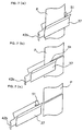
- Fig. 5 (a), (b),(c) illustrates a plan view, a cross sectional view, and a partial side view of the entrance guide 37 of Fig. 3.
- the entrance guide 37 comprises a couple of rectangular strips 42, 42 disposed in opposite sides of the transfer path Q respectively.
- the two strips 42, 42 are spaced from each other and extend lengthwisely in parallel to each other.
- each strip 42 has an upstream end 42a thereof along the transfer path Q deflecting outwardly so that the two strips 42, 42 are more spaced from each other at the end 42a opposite to the feed outlet 23 of the magazine 21.
- the two strips 42, 42 are sized with its width at the upstream end 42a greater than the width of the photosensitive material P.
- a flat sheet-like blade 51 is mounted as bridges over the two strips 42, 42 at the lengthwise inward end of the entrance guide 37A or 37B (inwardly of the covers 2a).
- the blade 51 may be a cutter blade of which the edge 51a is preferably slant along the width direction of the transfer path Q.
- While the first transfer unit 30 includes a stationary rail 44, a slide rail 45 is disposed in the entrance guide 37 corresponding to the shape and the location of the stationary rail 44.
- the slide rail 45 is fixedly mounted to one of the two strips 42.
- the stationary rail 44 is fitted so as to extend along the inner wall of the slide rail 45.
- the entrance guide 37 moves to and from the first transfer unit 30.
- the entrance guide 37 is a movable member for traveling forward and backward along the crosswise direction of the transfer path Q widthwisely of the photosensitive material P.
- the other strip 42 has a grip portion 42b of substantially an L shape provided on the proximal end thereof.
- the entrance guide 37 is maintained to a given location (where the photosensitive material P is conveyed in a normal mode through the corresponding entrance guide 37A or 37B, i.e. the corresponding entrance guide 37A or 37B is retracted within the apparatus body 1) by a holding means 46 which limits the forward and backward movement of the entrance guide 37 to the first transfer unit 30.
- the holding means 46 is so-called a roller catcher including an engaging projection 47 with a bulged head mounted to the inward end of the movable entrance guide 37 and an engaged member 50 which has a flexible joint member 49 of substantially a U shape, when seen from above, mounted on a pair of column-like pins 48, 48 arranged in parallel to each other and spaced from each other by a given distance in the first transfer unit 30.
- the engaging projection 47 advances towards the two pins 48, 48, separate the two pins 48, 48 from each other, and goes through the two pins 48, 48 until its head moves in the engage member 50.
- the neck of the engaging projection 47 just stays between the two pins 48, 48, the two pins 48, 48 are sprung back. Accordingly, the head of the engaging projection 47 is held at the proximal end with two pins 48, 48 thus canceling the forward and backward movement of the entrance guide 37.
- the blades 51A and 51B remain distanced from the photosensitive materials P when the entrance guides 37A and 37B are held not to move forward and backward (in the normal mode). In the normal mode, the photosensitive materials P being conveyed are free from the blades 51A and 51B. As the entrance guides 37A and 37B have been slid relatively, the blades 51A and 51B come to their positions for cutting the photosensitive materials P.
- the pressing rollers 32A and 32B are held by their respective roller holders 52 (a first roller holder 52A and a second roller holder 52B).
- the pressing rollers 32A and 32B are assembled integral with their respective roller holders 52A and 52B.
- the guide plate 35 is fixedly mounted to the first roller holder 52A so that its first guide 35a allows the photosensitive material P to be properly supported between the first advancing roller 31A and the first advancing roller guide 38A and its second guide 35b allows the photosensitive material P to be properly supported between the second advancing roller 31B and the second advancing roller guide 38B.
- the roller holders 52A and 52B are supported by pin-like supports 53 (a first support 53A and a second support 53B) at specific locations in the first transfer unit 30.
- the roller holders 52A and 52B are also arranged pivotable about their corresponding supports 53A and 53B. Accordingly, it is possible that the first pressing rollers 32A and the guide plate 35 held by the first roller holder 52A together are turned about the first support 53A while the second pressing rollers 32B held by the second roller holder 52B together are turned about the second first support 53B.
- Fig. 6 illustrates schematically the first transfer unit 30 where the pressing rollers 32 are disengaged from the advancing rollers 31.
- the "disengaged" condition means that the pressing rollers 32 are not completely removed from the first transfer unit 30 but only distanced from the advancing rollers 31 (while being supported by their respective supports 53) for the ease of carrying out a maintenance task about the advancing rollers 31.
- the turning of the first roller holder 52A about the first support 53A in the direction denoted by the arrow A can release the engagement between the first advancing roller 31A and the first pressing rollers 32A and then isolate the first pressing rollers 32A and the guide plate 35.
- the turning of the second roller holder 52B about the second support 53B in the direction denoted by the arrow B can release the engagement between the second advancing roller 31B and the second pressing rollers 32B and then isolate the second pressing rollers 32B.
- the pressing rollers 32A, 32B with the guide plate 35 which are pivotable about the supports 53A, 53B are properly positioned and engaged with their respective advancing rollers 31A, 31B by locking the roller holders 52A, 52B with their corresponding snap locks 36A, 36B.
- the photosensitive materials P are supplied and subjected to the exposure process and the development process of a photographic method.
- the entrance guide 37 is drawn out from the apparatus by pulling its grip 42b. While the entrance guide 37 is being withdrawn, the blades 51 move in a crosswise direction of the transfer path and cut off the photosensitive materials P (Fig. 7 (b)) . The photosensitive materials P are completely cut off with the blades 51 have been moved across the transfer path (Fig. 7 (c)) . The photosensitive materials P can successfully be cut off by pulling the entrance guide 37.
- the first transfer unit 30 is taken out from the apparatus body 1. After the first transfer unit 30 is taken out, the snap locks 36 holding the roller holders 52 are unlocked and the roller holders 52 are turned to disengage and separate the pressing rollers 32 and the guide plate 35 from the advancing rollers 31. By manually rotating the advancing rollers 31, the remaining of the photosensitive materials P in the first transfer unit 30 is removed off.
- the photographic processing apparatus of the embodiment can thus provide such advantages as described below.
- a jammed portion of the photosensitive material P can easily be cut and removed out from the apparatus body 1 by simply withdrawing the movable assembly 37 of the first transfer unit 30. This eliminates such a troublesome task as of accessing deep in the apparatus body 1 and cutting a jammed portion of the photosensitive material P with scissors or a cutter. In the embodiment, any unwanted portion of the photosensitive materials P can readily be cut and removed away.
- a maintenance job can be conducted about the advancing rollers 31 with the pressing rollers 32 not removed out but just separated from the advancing rollers 31.
- the removal of a jammed material or the maintenance will thus be carried out in a simpler manner than any conventional apparatus which has to first account the storage of removed components.
Claims (7)
- Schneidmechanismus für langes flächenkörperartiges Fördergut, wobei der Schneidmechanismus folgendes aufweist:- eine Einheit (30), die quer über einen Förderweg zum Befördern des langen flächenkörperartigen Fördergutes (P) in einer Längsrichtung angeordnet ist;- ein bewegliches Element (37, 206), das einen Schlitz aufweist und auf dem Förderweg in Querrichtung relativ zu dem Förderweg vorgesehen ist; und- ein an dem beweglichen Element (37, 206) angebrachtes Messer (51, 211) zum Schneiden des langen flächenkörperartigen Fördergutes (P) in dessen Querrichtung, wenn das bewegliche Element (27, 206) in Querrichtung bewegt wird,
dadurch gekennzeichnet,
daß bei dem beweglichen Element (37, 206) der Schlitz breiter ist als die Breite des langen flächenkörperartigen Fördergutes (P), so daß das lange flächenkörperartige Fördergut (P) in dem Schlitz eingeschlossen wird, um dadurch das lange flächenkörperartige Fördergut zu veranlassen, sich durch den Schlitz hindurchzubewegen, wobei das lange flächenkörperartige Fördergut (P) den Schlitz in einer ersten Position durchläuft,
daß das bewegliche Element (37, 206) dazu ausgebildet ist, sich zwischen der ersten Position und einer zweiten Position vor und zurück zu bewegen, so daß es den Förderweg von dessen einem Ende in Breitenrichtung bis zu dessen anderem Ende quert,
daß ein Greifbereich (42b, 209) an einem proximalen Ende des beweglichen Elements (37, 206) vorgesehen ist, um ein Ziehen des beweglichen Elements zu ermöglichen und dieses dadurch aus der ersten Position in die zweite Position zu bewegen,
und daß das Messer (51, 211) an dem einen Ende des Schlitzes vorgesehen und dazu ausgebildet ist, das lange flächenkörperartige Fördergut (P) in dessen Breitenrichtung zu schneiden, während das bewegliche Element (37, 206) aus der ersten Position in die zweite Position bewegt wird. - Mechanismus nach Anspruch 1,
wobei das bewegliche Element (37) ein Paar Streifen (42) aufweist, die einander gegenüberliegend beidseits des Förderweges angeordnet sind, und wobei das Messer (51) zwischen den beiden Streifen (42) angeordnet ist. - Mechanismus nach Anspruch 2,
wobei die beiden Streifen (42) nach außen gebogen sind und an dem förderwegseitig bewegungsaufwärtigen Ende (42a) zunehmend voneinander beabstandet sind. - Mechanismus nach einem der Ansprüche 1 bis 3,
weiterhin mit einer Halteeinrichtung (46) zum Begrenzen der nach vorn und nach hinten gehenden Bewegung des beweglichen Elements (37) in Relation zu der Einheit (30) und zum Halten des beweglichen Elements (37) in einer bestimmten Position. - Mechanismus nach Anspruch 1,
wobei das bewegliche Element (206) ein mit einem durchgehenden Schlitz (210) versehenes Element (208) aufweist, das zum Ausführen einer Bewegung in Breitenrichtung des flächenkörperartigen Fördergutes (P) ausgebildet ist und folgendes aufweist:- einen darin vorgesehenen durchgehenden Schlitz (210), durch den hindurch das flächenkörperartige Fördergut (P) den Förderweg entlang befördert wird, und- ein Messer (211), das an dem einen Ende von dessen durchgehendem Schlitz in Breitenrichtung des flächenkörperartigen Fördergutes (P) vorgesehen ist, wobei das sich durch den durchgehenden Schlitz (210) hindurch erstreckende flächenkörperartige Fördergut (P) mittels des Messers (211) auseinander geschnitten werden kann, wenn das mit dem durchgehenden Schlitz versehene Element (208) aus der einen Position in die andere Position bewegt wird. - Mechanismus nach Anspruch 5,
der weiterhin folgendes aufweist:- Vorspannungseinrichtungen (207) zum Drängen des mit dem durchgehenden Schlitz versehenen Elements (208) in eine entgegengesetzte Richtung zu der Richtung zum Schneiden des flächenkörperartigen Fördergutes (P), und- Positioniereinrichtungen (212) zum Positionieren des mit dem durchgehenden Schlitz versehenen Elements (208) derart, daß das flächenkörperartige Fördergut (P) durch den durchgehenden Schlitz (210) des mit dem durchgehenden Schlitz versehenen Elements (208) hindurch befördert wird,
wobei die Positioniereinrichtungen (212) mit einem Anschlag zum Stoppen der Bewegung des mit dem durchgehenden Schlitz (208) versehenen Elements (208) versehen ist, das mit der Vorspannungskraft der Vorspannungseinrichtungen (207) beaufschlagt wird. - Mechanismus nach Anspruch 6,
wobei die Vorspannungseinrichtungen (207) eine Spiralfeder aufweisen und das mit dem durchgehenden Schlitz versehene Element (208) Bestandteil der Spiralfeder ist.
Applications Claiming Priority (4)
| Application Number | Priority Date | Filing Date | Title |
|---|---|---|---|
| JP11212510A JP2001042444A (ja) | 1999-07-27 | 1999-07-27 | 写真処理機及び感光材料収容マガジン |
| JP21251099 | 1999-07-27 | ||
| JP26922099 | 1999-09-22 | ||
| JP26922099A JP3596745B2 (ja) | 1999-09-22 | 1999-09-22 | シート状搬送物の切断機構および写真処理装置 |
Publications (2)
| Publication Number | Publication Date |
|---|---|
| EP1072946A1 EP1072946A1 (de) | 2001-01-31 |
| EP1072946B1 true EP1072946B1 (de) | 2006-03-01 |
Family
ID=26519279
Family Applications (1)
| Application Number | Title | Priority Date | Filing Date |
|---|---|---|---|
| EP20000116312 Expired - Lifetime EP1072946B1 (de) | 1999-07-27 | 2000-07-27 | Schneidevorrichtung für blattförmiges gefördertes Material in einem fotografischen Behandlungsgerät |
Country Status (4)
| Country | Link |
|---|---|
| US (1) | US6722244B1 (de) |
| EP (1) | EP1072946B1 (de) |
| CN (1) | CN1212258C (de) |
| DE (1) | DE60026207T8 (de) |
Family Cites Families (51)
| Publication number | Priority date | Publication date | Assignee | Title |
|---|---|---|---|---|
| US697902A (en) * | 1902-01-21 | 1902-04-15 | Freeman Leeman Tripp | Linoleum-cutter. |
| US1759599A (en) * | 1927-05-23 | 1930-05-20 | Horace C Yates | Adhesive-tape dispenser |
| US3176572A (en) * | 1962-10-05 | 1965-04-06 | Ralph L Comet | Tape cutting and dispensing device |
| US3199394A (en) * | 1962-12-31 | 1965-08-10 | Johnson & Johnson | Dispenser for adhesive tape |
| US3277761A (en) * | 1963-08-27 | 1966-10-11 | Donald F Dreher | Web severing apparatus |
| DE1761538B1 (de) * | 1968-06-04 | 1971-09-09 | Hell Rudolf Dr Ing Kg | Vorrichtung zum querschneiden bahnfoermiger materialien |
| JPS5035706B1 (de) | 1969-02-20 | 1975-11-18 | ||
| DE1912759A1 (de) * | 1969-03-13 | 1970-10-01 | Agfa Gevaert Ag | Vorrichtung zum Sortieren von auf einen Papierstreifen hintereinander aufkopierten und entwickelten fotografischen Bildern |
| US3659487A (en) * | 1970-03-30 | 1972-05-02 | Kimberly Clark Co | Portable manually operable cutting machine for rolled sheet material |
| US3636408A (en) * | 1970-05-26 | 1972-01-18 | Technical Tape Corp | Tape dispenser with static electricity neutralizer |
| NL141256B (nl) * | 1970-10-22 | 1974-02-15 | Theodorus Michael Jozef Van Ev | Inrichting voor het afsnijden van een willekeurige lengte van een tapijtbaan. |
| CH587106A5 (de) * | 1973-10-12 | 1977-04-29 | Granger Maurice | |
| US4156382A (en) * | 1977-12-20 | 1979-05-29 | General Electric Company | Bag sealer and cutter assembly |
| US4147427A (en) * | 1978-02-24 | 1979-04-03 | Pako Corporation | Variable working distance photographic printer with stationary paper magazines |
| US4175460A (en) * | 1978-03-27 | 1979-11-27 | Mcphail John D | Felt, belt, and fabric trimmer |
| US4245536A (en) * | 1979-08-20 | 1981-01-20 | Scott Paper Company | Hinged cutter track |
| JPS5825678A (ja) * | 1981-08-10 | 1983-02-15 | Konishiroku Photo Ind Co Ltd | 複写機等の記録紙案内装置 |
| DE3203943A1 (de) | 1982-02-05 | 1983-08-25 | Karl 7631 Meißenheim Gallus | Verfahren zum schneiden von fotosatz-filmen o.dgl. sowie vorrichtung zur durchfuehrung des verfahrens |
| US4823663A (en) * | 1987-03-02 | 1989-04-25 | Xerox Corporation | Cut sheet roll supply |
| US4827817A (en) * | 1987-05-07 | 1989-05-09 | Jane Grohoski | Sanitary napkin dispenser |
| US5107734A (en) * | 1987-07-22 | 1992-04-28 | Armbruster Joseph M | Electrically powered dispenser for rolled sheet material |
| US4815874A (en) * | 1988-02-01 | 1989-03-28 | Kroy Inc. | Thermal printer and tape-ribbon cartridge with cut-off mechanism |
| US5044241A (en) * | 1990-03-20 | 1991-09-03 | Labrecque Normand F | Cutting apparatus for wrap film |
| US5007171A (en) * | 1990-05-07 | 1991-04-16 | Horning Jr John H | Bag opener apparatus |
| US5076555A (en) * | 1990-07-25 | 1991-12-31 | Bunch Jr Earnest B | Apparatus for partially severing strip of paper along lines offset from lines of weakening in the paper |
| US5103710A (en) * | 1991-03-19 | 1992-04-14 | Ross Scott S | Media handling and cutting device |
| MY108892A (en) * | 1992-07-14 | 1996-11-30 | Nec Corp | Paper cutting device using a movable cutting wheel |
| DE4229518A1 (de) * | 1992-09-04 | 1994-03-10 | Agfa Gevaert Ag | Schneideinrichtung für Fotopapier |
| US5853101A (en) * | 1993-01-21 | 1998-12-29 | Primary Delivery Systems, Inc. | Blister pack opener |
| JP2570091B2 (ja) * | 1993-03-30 | 1997-01-08 | マックス株式会社 | テーププリンタ |
| JPH06286738A (ja) * | 1993-03-31 | 1994-10-11 | Japan Tobacco Inc | 帯状材の切断供給装置 |
| GB9314386D0 (en) * | 1993-07-12 | 1993-08-25 | Esselte Dymo Nv | A cassette for a thermal printer |
| US5357679A (en) * | 1993-10-15 | 1994-10-25 | Hanna Lori A | Bag opening device |
| US5398576A (en) * | 1994-03-09 | 1995-03-21 | Chiu; Kuang-Wu | Cutting device for a roll of protective film |
| JP3144212B2 (ja) | 1994-03-30 | 2001-03-12 | ノーリツ鋼機株式会社 | 写真感光材料の供給装置 |
| JP2940411B2 (ja) * | 1994-09-13 | 1999-08-25 | ノーリツ鋼機株式会社 | 写真焼付機における感光材料の案内装置 |
| IT1278337B1 (it) * | 1994-09-19 | 1997-11-17 | Durst Phototechnik Spa | Disposizione per la messa in tensione di materiale bobinato. |
| JPH08234314A (ja) | 1994-12-26 | 1996-09-13 | Konica Corp | 写真焼付装置、ロールマガジン保持装置及び感光材料移送装置 |
| US5555624A (en) * | 1995-02-13 | 1996-09-17 | Mccracken; Brian | Package opener |
| JPH08254809A (ja) | 1995-03-17 | 1996-10-01 | Fuji Photo Film Co Ltd | 写真プリンタの切断装置 |
| WO1996036551A1 (de) * | 1995-05-15 | 1996-11-21 | Pius Schuler | Folienspender |
| US5771769A (en) | 1995-08-22 | 1998-06-30 | Eastman Kodak Company | Externally driveable cassette for light-sensitive web material, including knife for cuttng material |
| US6145423A (en) * | 1995-09-15 | 2000-11-14 | Moore Business Forms, Inc. | Semi-automatic dispenser for linerless labels |
| DE19615370A1 (de) * | 1996-04-19 | 1997-10-23 | Voith Sulzer Papiermasch Gmbh | Verfahren und Vorrichtung zum Durchtrennen einer laufenden Warenbahn |
| JPH1035964A (ja) * | 1996-07-22 | 1998-02-10 | Brother Ind Ltd | 用紙移送機構、これを備えた画像記録装置、および画像読取記録装置 |
| IL119980A (en) * | 1997-01-08 | 2000-07-16 | Gazit Eran | Device for opening packets and for dispensing the contents thereof |
| US5894978A (en) * | 1997-06-27 | 1999-04-20 | Jeffrey M. Welch | Flexible material cutter |
| JP3839141B2 (ja) * | 1997-09-03 | 2006-11-01 | 富士写真フイルム株式会社 | プリンタのカッター装置 |
| EP0909651B1 (de) * | 1997-10-18 | 2001-07-11 | Esselte N.V. | Streifendrucker mit einer Schneidvorrichtung mit einem Führungsmechanismus |
| US6125741A (en) * | 1999-08-05 | 2000-10-03 | Shorter; Carolyn | Food cutting device |
| US6223639B1 (en) * | 1999-08-13 | 2001-05-01 | Su-Hui Chen | Aluminum foil safety fixture |
-
2000
- 2000-07-27 CN CNB001211277A patent/CN1212258C/zh not_active Expired - Fee Related
- 2000-07-27 DE DE2000626207 patent/DE60026207T8/de active Active
- 2000-07-27 EP EP20000116312 patent/EP1072946B1/de not_active Expired - Lifetime
- 2000-07-27 US US09/626,901 patent/US6722244B1/en not_active Expired - Fee Related
Also Published As
| Publication number | Publication date |
|---|---|
| DE60026207T2 (de) | 2006-11-23 |
| US6722244B1 (en) | 2004-04-20 |
| DE60026207D1 (de) | 2006-04-27 |
| CN1283580A (zh) | 2001-02-14 |
| EP1072946A1 (de) | 2001-01-31 |
| CN1212258C (zh) | 2005-07-27 |
| DE60026207T8 (de) | 2007-03-29 |
Similar Documents
| Publication | Publication Date | Title |
|---|---|---|
| JPH082754A (ja) | インクジェット記録装置 | |
| EP1013456B1 (de) | Bilderzeugungsgerät | |
| JP2846384B2 (ja) | 印画紙プリンタ用の印画紙供給装置および供給方法 | |
| JPH0224119Y2 (de) | ||
| EP1072946B1 (de) | Schneidevorrichtung für blattförmiges gefördertes Material in einem fotografischen Behandlungsgerät | |
| JP2637661B2 (ja) | レーザプリンタ | |
| JP3596745B2 (ja) | シート状搬送物の切断機構および写真処理装置 | |
| JPH06219581A (ja) | シート供給装置 | |
| JP2551596Y2 (ja) | プリンタ | |
| JP3928511B2 (ja) | 記録材料の切断方法、及び、同方法に用いられるカッタ | |
| JP3487535B2 (ja) | ロール紙ユニット及びそれを備えた画像形成装置 | |
| CA1244846A (en) | Apparatus and method for advancing photographic print paper | |
| US20230286771A1 (en) | Image recording apparatus | |
| JP7298167B2 (ja) | シート搬送装置及び画像形成システム | |
| EP1288004B1 (de) | Eine versiegelte Kammer zur Steuerung des Umgebungszustandes eines Druckmediums | |
| US5638157A (en) | Film processing apparatus | |
| JP2003173010A (ja) | コントロールストリップ用ホルダ及び現像処理装置 | |
| JPH07117247A (ja) | サーマルプリンタ | |
| JPH0881099A (ja) | 写真焼付機における感光材料の案内装置 | |
| JPH09114152A (ja) | 画像形成装置 | |
| JP2583771B2 (ja) | 画像記録装置 | |
| JP2001075186A (ja) | 感光材料搬送手段およびこれを用いた写真処理装置 | |
| JPH04301645A (ja) | 走査型露光装置 | |
| JPH01285535A (ja) | 画像形成装置 | |
| JP2000264500A (ja) | 画像形成装置のロール紙給紙装置 |
Legal Events
| Date | Code | Title | Description |
|---|---|---|---|
| PUAI | Public reference made under article 153(3) epc to a published international application that has entered the european phase |
Free format text: ORIGINAL CODE: 0009012 |
|
| AK | Designated contracting states |
Kind code of ref document: A1 Designated state(s): DE FR GB |
|
| AX | Request for extension of the european patent |
Free format text: AL;LT;LV;MK;RO;SI |
|
| 17P | Request for examination filed |
Effective date: 20010517 |
|
| AKX | Designation fees paid |
Free format text: DE FR GB |
|
| 17Q | First examination report despatched |
Effective date: 20040406 |
|
| GRAP | Despatch of communication of intention to grant a patent |
Free format text: ORIGINAL CODE: EPIDOSNIGR1 |
|
| GRAS | Grant fee paid |
Free format text: ORIGINAL CODE: EPIDOSNIGR3 |
|
| GRAA | (expected) grant |
Free format text: ORIGINAL CODE: 0009210 |
|
| AK | Designated contracting states |
Kind code of ref document: B1 Designated state(s): DE FR GB |
|
| REG | Reference to a national code |
Ref country code: GB Ref legal event code: FG4D |
|
| REF | Corresponds to: |
Ref document number: 60026207 Country of ref document: DE Date of ref document: 20060427 Kind code of ref document: P |
|
| PG25 | Lapsed in a contracting state [announced via postgrant information from national office to epo] |
Ref country code: GB Free format text: LAPSE BECAUSE OF NON-PAYMENT OF DUE FEES Effective date: 20060727 |
|
| ET | Fr: translation filed | ||
| PLBE | No opposition filed within time limit |
Free format text: ORIGINAL CODE: 0009261 |
|
| STAA | Information on the status of an ep patent application or granted ep patent |
Free format text: STATUS: NO OPPOSITION FILED WITHIN TIME LIMIT |
|
| 26N | No opposition filed |
Effective date: 20061204 |
|
| GBPC | Gb: european patent ceased through non-payment of renewal fee |
Effective date: 20060727 |
|
| REG | Reference to a national code |
Ref country code: FR Ref legal event code: ST Effective date: 20070330 |
|
| PG25 | Lapsed in a contracting state [announced via postgrant information from national office to epo] |
Ref country code: FR Free format text: LAPSE BECAUSE OF NON-PAYMENT OF DUE FEES Effective date: 20060731 |
|
| PGFP | Annual fee paid to national office [announced via postgrant information from national office to epo] |
Ref country code: DE Payment date: 20100721 Year of fee payment: 11 |
|
| PG25 | Lapsed in a contracting state [announced via postgrant information from national office to epo] |
Ref country code: DE Free format text: LAPSE BECAUSE OF NON-PAYMENT OF DUE FEES Effective date: 20120201 |
|
| REG | Reference to a national code |
Ref country code: DE Ref legal event code: R119 Ref document number: 60026207 Country of ref document: DE Effective date: 20120201 |