EP1072792A2 - Swash plate compressor - Google Patents
Swash plate compressor Download PDFInfo
- Publication number
- EP1072792A2 EP1072792A2 EP00116016A EP00116016A EP1072792A2 EP 1072792 A2 EP1072792 A2 EP 1072792A2 EP 00116016 A EP00116016 A EP 00116016A EP 00116016 A EP00116016 A EP 00116016A EP 1072792 A2 EP1072792 A2 EP 1072792A2
- Authority
- EP
- European Patent Office
- Prior art keywords
- valve plate
- separator
- compressor
- cylinder
- suction
- Prior art date
- Legal status (The legal status is an assumption and is not a legal conclusion. Google has not performed a legal analysis and makes no representation as to the accuracy of the status listed.)
- Withdrawn
Links
- 238000005192 partition Methods 0.000 claims abstract description 52
- 230000002093 peripheral effect Effects 0.000 claims description 12
- 239000003507 refrigerant Substances 0.000 description 12
- 235000014676 Phragmites communis Nutrition 0.000 description 3
- 238000004378 air conditioning Methods 0.000 description 3
- 238000005266 casting Methods 0.000 description 3
- 238000005242 forging Methods 0.000 description 3
- 230000010349 pulsation Effects 0.000 description 3
- XEEYBQQBJWHFJM-UHFFFAOYSA-N Iron Chemical compound [Fe] XEEYBQQBJWHFJM-UHFFFAOYSA-N 0.000 description 2
- 230000004323 axial length Effects 0.000 description 2
- 238000007599 discharging Methods 0.000 description 2
- 239000013013 elastic material Substances 0.000 description 2
- 229910052751 metal Inorganic materials 0.000 description 2
- 239000002184 metal Substances 0.000 description 2
- 239000007769 metal material Substances 0.000 description 2
- 229910052782 aluminium Inorganic materials 0.000 description 1
- XAGFODPZIPBFFR-UHFFFAOYSA-N aluminium Chemical compound [Al] XAGFODPZIPBFFR-UHFFFAOYSA-N 0.000 description 1
- 229910052742 iron Inorganic materials 0.000 description 1
- 238000005057 refrigeration Methods 0.000 description 1
- 239000011347 resin Substances 0.000 description 1
- 229920005989 resin Polymers 0.000 description 1
- 238000006748 scratching Methods 0.000 description 1
- 230000002393 scratching effect Effects 0.000 description 1
Images




Classifications
-
- F—MECHANICAL ENGINEERING; LIGHTING; HEATING; WEAPONS; BLASTING
- F04—POSITIVE - DISPLACEMENT MACHINES FOR LIQUIDS; PUMPS FOR LIQUIDS OR ELASTIC FLUIDS
- F04B—POSITIVE-DISPLACEMENT MACHINES FOR LIQUIDS; PUMPS
- F04B39/00—Component parts, details, or accessories, of pumps or pumping systems specially adapted for elastic fluids, not otherwise provided for in, or of interest apart from, groups F04B25/00 - F04B37/00
- F04B39/12—Casings; Cylinders; Cylinder heads; Fluid connections
- F04B39/125—Cylinder heads
-
- F—MECHANICAL ENGINEERING; LIGHTING; HEATING; WEAPONS; BLASTING
- F04—POSITIVE - DISPLACEMENT MACHINES FOR LIQUIDS; PUMPS FOR LIQUIDS OR ELASTIC FLUIDS
- F04B—POSITIVE-DISPLACEMENT MACHINES FOR LIQUIDS; PUMPS
- F04B27/00—Multi-cylinder pumps specially adapted for elastic fluids and characterised by number or arrangement of cylinders
- F04B27/08—Multi-cylinder pumps specially adapted for elastic fluids and characterised by number or arrangement of cylinders having cylinders coaxial with, or parallel or inclined to, main shaft axis
- F04B27/10—Multi-cylinder pumps specially adapted for elastic fluids and characterised by number or arrangement of cylinders having cylinders coaxial with, or parallel or inclined to, main shaft axis having stationary cylinders
- F04B27/1009—Distribution members
-
- F—MECHANICAL ENGINEERING; LIGHTING; HEATING; WEAPONS; BLASTING
- F04—POSITIVE - DISPLACEMENT MACHINES FOR LIQUIDS; PUMPS FOR LIQUIDS OR ELASTIC FLUIDS
- F04B—POSITIVE-DISPLACEMENT MACHINES FOR LIQUIDS; PUMPS
- F04B27/00—Multi-cylinder pumps specially adapted for elastic fluids and characterised by number or arrangement of cylinders
- F04B27/08—Multi-cylinder pumps specially adapted for elastic fluids and characterised by number or arrangement of cylinders having cylinders coaxial with, or parallel or inclined to, main shaft axis
- F04B27/10—Multi-cylinder pumps specially adapted for elastic fluids and characterised by number or arrangement of cylinders having cylinders coaxial with, or parallel or inclined to, main shaft axis having stationary cylinders
- F04B27/1036—Component parts, details, e.g. sealings, lubrication
- F04B27/1081—Casings, housings
Definitions
- the present invention relates to a piston-type compressor for air-conditioning vehicles.
- FIG. 8 shows this type of compressor.
- a front housing member 101 is joined to the front (left in Fig. 8) of a cylinder block 102.
- a rear housing member 103 is joined to the rear of the cylinder block 102 through a valve plate 104.
- a drive shaft 105 is supported by the front housing member 101 and the cylinder block 102.
- Several cylinder bores 106 are formed in the cylinder block 102. The cylinder bores 106 are equally spaced from the axis L of the drive shaft 105 at equal angular intervals. Pistons 107 are located in the corresponding cylinder bores 106.
- An annular partition wall 108 is formed in the rear housing member 103 and is centered on the axis L.
- the end surface 108a of the partition wall 108 contacts the valve plate 104.
- a suction chamber 109 is formed inside the partition wall 108, and a discharge chamber 110 is formed outside the partition wall 108.
- the valve plate 104 includes suction ports 104a, suction valves 104b, discharge ports 104c, and discharge valves 104.
- Rotation of the drive shaft 105 is converted into reciprocation of the pistons 107.
- refrigerant gas is drawn from the suction chamber 109 to the cylinder bores 106 through the corresponding suction ports 104a and suction valves 104b.
- the refrigerant gas in the cylinder bores 106 is compressed and discharged to the discharge chamber 110 through the corresponding discharge ports 104c and discharge valves 104d.
- the cycle of drawing, compressing, and discharging gas is repeated.
- the partition wall must directly contact the valve plate 104 to separate the discharge chamber 110 from the suction chamber 109. This limits the shape and size of the partition wall 108, which reduces flexibility in determining the ratio between the volume of suction chamber 109 and that of the discharge chamber 110.
- each discharge valve 104d presses a base portion of each discharge valve 104d such that the function of each discharge valve 104d, which is a reed valve, is stable. Accordingly, the shape and size of the partition wall 108 must be formed such that the discharge valves 104d are pressed properly. This also limits the flexibility in determining the ratio of the volume of the suction chamber 109 to that of the discharge chamber 110.
- An objective of the present invention is to provide a piston-type compressor that has flexibility in determining the ratio between the volume of a suction chamber and that of a discharge chamber in order to efficiently attenuate the pressure pulsation of refrigerant gas without increasing the size of the compressor.
- the present invention provides a compressor with a cylinder block and rear housing fixed to the cylinder block.
- the cylinder block has a plurality of cylinder bores arranged along a first phantom circle about an axis of a drive shaft supported by the cylinder block.
- Each of the cylinder bore has a piston movably disposed therein.
- a partition is formed within the rear housing to define a discharge chamber and a suction chamber in the rear housing.
- a valve plate is interposed between the chambers and the cylinder bore to selectively connect and disconnect the chambers with the cylinder bore.
- a separator is located between an end of the partition and the valve plate to urge the valve plate against the cylinder block on a second phantom circle about the axis of the drive shaft in such a manner as to maintain selectively connecting and disconnecting the chambers with the cylinder bore.
- a single-headed-piston compressor for air-conditioning vehicles according to a first embodiment of the present invention will now be described.
- a front housing member 11 is joined to the front of a cylinder block 12.
- a rear housing member 13 is joined to the rear of the cylinder block 12 through a valve plate 14.
- the front housing member 11, the cylinder block 12, and the rear housing member 13 are fastened by bolts 28 and form a compressor housing.
- the housing members 11, 12, 13 are formed by forging or casting using metal materials such as aluminum or iron.
- a crank chamber 15 is formed between the front housing member 11 and the cylinder block 12.
- a drive shaft 16, which passes through the crank chamber 15, is supported by the front housing member 11 and the cylinder block 12.
- the drive shaft 16 is connected to and is driven by an external drive source such as an engine (not shown).
- Cylinder bores 17 are formed in the cylinder block 12.
- the cylinder bores 17 are equally spaced from the axis L of the drive shaft 16 at equal angular intervals.
- Single-headed pistons 18 are located in the corresponding cylinder bores 17.
- a space for compressing refrigerant gas is defined in each cylinder bore 17 by the corresponding piston 17 and the valve plate 14.
- a swash plate 19 is supported by the drive shaft 16 in the crank chamber 15 to rotate with the drive shaft 16.
- the pistons 18 are coupled to the periphery of the swash plate 19 through shoes 20. Rotation of the drive shaft 16 is converted into reciprocation of the pistons 18 through the swash plate 19 and the shoes 20.
- a discharge chamber 22 is formed in the rear housing member 13 to surround a suction chamber 21.
- the suction chamber 21 is connected to the discharge chamber 22 by an external refrigerant circuit, which includes a condenser, an expansion valve, and an evaporator (not shown).
- the external refrigerant circuit and the compressor form a refrigeration circuit for air-conditioning vehicles.
- the valve plate 14 includes a suction valve plate 25, a port plate 26, and a discharge valve plate 27.
- Suction ports 26a which are formed in the port plate 26, connect the corresponding cylinder bores 17 with the suction chamber 21.
- Suction valves 25a which are reed valves, are formed in the suction valve plate 25.
- the suction valves 25a open and close the corresponding suction ports 26a.
- Discharge ports 26b are formed in the port plate 26 outward of the suction ports 26a.
- the discharge ports 26b connect the corresponding cylinder bores 17 with the discharge chamber 22.
- Discharge valves 27a which are reed valves, are formed in the discharge valve plate 27.
- the discharge valves 27a open and close the corresponding discharge ports 26b.
- the rear end of the rear housing member 13 is closed.
- the front end 31a of the rear housing member 13 is joined to the rear end of the cylinder block 12 through a gasket 32 and the valve plate 14 by the bolts 28.
- An annular partition 33 is integrally formed in the rear housing member 13 inward of the peripheral wall 31.
- the partition 33 which projects frontward, is shorter than the peripheral wall 31. Accordingly, inner and outer chambers are formed in the rear housing 13.
- the compressor includes a separator 34, which is an annular metal plate.
- the separator 34 includes a tapered retainer 36, which is formed on a front surface 34a, and an offset portion 35, which is radially inward of the tapered retainer 36.
- the separator 34 is located between the front surface 33a of the partition 33 and the rear surface of the valve plate 14 (or discharge valve plate 27).
- the annular partition 33 is centered on the axis L, and its front surface 33a contacts the rear surface 34b of the separator 34.
- the gasket 37 is located between the front surface 33a of the partition 33 and the rear surface 34b of the separator 34.
- the location of contact between the offset portion 35 and the valve plate 14 (or discharge valve plate 27) is inward of the location of contact between the offset portion 35 and the partition 33.
- the maximum opening size of each discharge valve 27a is limited by the retainer 36 as shown by the broken line in Fig. 2.
- the inner chamber of the rear housing member 13 is closed by the separator 34 and the valve plate 14, which forms the suction chamber 21.
- the outer chamber of the rear housing member 13 is closed by the valve plate 14 and the separator 34, which forms the discharge chamber 22.
- the discharge chamber 22 is separated from the suction chamber 21.
- the partition 33 contacts the separator 34 outward of the offset portion 35.
- the partition 108 directly contacts the valve plate 104.
- the discharge valves 27a would not be properly supported, and the suction ports 26a would not completely be separated from the discharge ports 26b.
- the partition 33 is sealed to the valve plate 14 through the offset portion 35 at a location that is like that of the prior art. Accordingly, the offset portion 35 properly separates the suction ports 26a from the discharge ports 26b and properly supports the proximal portion of each discharge valve 27a.
- the separator 34 were integrally formed with the partition 33, there would be no need to place the independent separator 34 and the gasket 37 between the partition 33 and the valve plate 14.
- the complicated shape of the partition 33 makes it hard to detach the rear housing 13 from a mold when forging or casting. Accordingly, it is necessary to choose the shape of the partition 33 to facilitate forging or casting. Therefore, it is preferred that the separator 34 be independent from the partition 33.
- the offset portion 35 of the separator 34 contacts the valve plate 14 to separate the suction ports 26a from the discharge ports 26b.
- the shape and size of the partition 33 is arbitrarily determined as long as the partition contacts the rear surface of the separator 34 and the suction chamber 21 is separated from the discharge chamber 22. This increases the design flexibility of the suction chamber 21 and the discharge chamber 22. That is, the ratio between the volume of the suction chamber 21 and that of the discharge chamber 22 can be freely determined regardless of the positions of the ports 104a, 104c and the discharge valves 104d.
- the separator 34 includes the retainer 36, which determines the maximum opening size of the discharge valves 27. Accordingly, there is no need for an independent retainer, which reduces the number of parts.
- the retainer 36 is a tapered surface that limits the movement of each flexible discharge valve 27a. Accordingly, the discharge valves 27a are entirely supported by the retainer 36, which prevents concentration of stress and improves durability.
- a gasket 37 made of metal plate covered with the elastic material, is located between the partition 33 and the separator 34, which are made of metallic materials. Accordingly, the partition 33 and the separator 34 are firmly joined, which effectively separates the suction chamber 21 from the discharge chamber 22. The gasket also prevents the partition 33 from scratching the separator 34.
- the separator 34 is disc-shaped. In the first embodiment, the separator 34 is annular so that the suction chamber 21 is connected with the suction ports 26a by the center hole. In the second embodiment, the separator 34 includes through holes 41 corresponding to the suction ports 26a. The through holes 41 connect the suction chamber 21 with the suction ports 26a.
- the central part of the separator 34 is fastened to the center of the valve plate 14 by a bolt and nut 42. Accordingly, the separator 34 is firmly joined to the valve plate 14 regardless of the pressing force between the partition 33 and the cylinder block 12. This assures stable operation of the discharge valves 27a and prevents leakage of refrigerant gas between the separator 34 and the valve plate 14.
- the plates 25-27 are also firmly held together, which prevents leakage of gas between them.
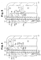
- FIG. 4 A third embodiment of the present invention, which is shown in Fig. 4, will now be described.
- the third embodiment permits axial variation of the position of the rear housing member 13.
- the peripheral wall 31 is joined to the cylinder block 12 through the gasket 32 and the valve plate 14. Since the gasket 32 and the valve plate 14 have almost no elasticity in the axial direction, they do not permit the location of the front end 31a of the peripheral wall 31 to vary significantly against the rear end of the cylinder block 12.
- a resin elastic seal which is an O-ring 45 made of elastic material, such as rubber, is located between the peripheral wall 31 and the cylinder block 12, instead of the gasket 32.
- the space between the peripheral wall 31 and the cylinder block 12 varies by the deformation of the O-ring 45. Accordingly, the dimensional errors of the peripheral wall 31 and the partition 33 in the axial direction are compensated for by the deformation of the O-ring 45. As a result, the separator 34 and the valve plate 14 are properly pressed between the partition 33 and the cylinder block 12, which solves the above mentioned problems and extends the life of the valve plate 14.
- the present invention can further be embodied as follows.
- the radius of the partition 33 of the first embodiment may be smaller, which increases the volume of the discharge chamber 22 without increasing the size of the rear housing member 13.
- the retainer 36 may be omitted from the separator 34, and a separable retainer 51 may be located on the valve plate 14.
- the separator 34 is formed such that the retainer 51 does not interfere with the periphery of the separator 34. That is, the offset portion 35 extends toward the valve plate 14.
- the separator 34 can be simply formed as a cylinder. In other words, only the offset portion 35 of Fig. 6 forms the separator 34.
- the radial thickness of the offset portion 35 is such that there is flexibility in designing the volumes of the suction chamber 21 and the discharge chamber 22 in the rear housing 13.
- the suction chamber 21 is located inward of the discharge chamber 22 in the rear housing member 13.
- the suction chamber 21 may be located outward of the discharge chamber 22 in the rear housing member 13.
- the present invention can also be embodied in a double-headed piston compressor. That is, a separator according to the present invention may be located between the partition and the valve plate at least in one of the rear or front side of the suction chamber and discharge chamber.
- a compressor has a cylinder block (12) and rear housing (13) fixed to the cylinder block.
- the cylinder block has a plurality of cylinder bores (17) arranged along a first phantom circle about an axis (L) of a drive shaft (16) supported by the cylinder block.
- Each of the cylinder bore has a piston (18) movably disposed therein.
- a partition (33) is formed within the rear housing to define a discharge chamber (21) and a suction chamber (22) in the rear housing.
- a valve plate (14) is interposed between the chambers and the cylinder bores to selectively connect and disconnect the chambers with the cylinder bores.
- a separator (34) is located between an end of the partition and the valve plate to urge the valve plate against the cylinder block on a second phantom circle about the axis of the drive shaft in such a manner as to maintain selectively connecting and disconnecting the chambers with the cylinder bores.
Landscapes
- Engineering & Computer Science (AREA)
- Mechanical Engineering (AREA)
- General Engineering & Computer Science (AREA)
- Compressors, Vaccum Pumps And Other Relevant Systems (AREA)
- Compressor (AREA)
- Check Valves (AREA)
Abstract
Description
Claims (10)
- A compressor having a cylinder block (12) and rear housing (13) fixed to the cylinder block, said cylinder block having a plurality of cylinder bores (17) arranged along a first phantom circle about an axis (L) of a drive shaft (16) supported by the cylinder block, each cylinder bore has a piston (18) movably disposed therein, wherein a partition (33) is formed within the rear housing to define a discharge chamber (21) and a suction chamber (22) in the rear housing, and wherein a valve plate (14) is interposed between the chambers and the cylinder bores to selectively connect and disconnect the chambers with the cylinder bore, said compressor being characterized by a separator (34) located between an end of the partition and the valve plate to urge the valve plate against the cylinder block on a second phantom circle about the axis of the drive shaft in such a manner as to maintain selectively connecting and disconnecting the chambers with the cylinder bore.
- The compressor as set forth in Claim 1, characterized in that said valve plate includes suction ports (26a) and suction valves (25a) both selectively connecting and disconnecting the suction chamber with the cylinder bores, said valve plate further includes discharge ports (26b) and discharge valve (27a) both selectively connecting and disconnecting the discharge chamber with the cylinder bores, and said separator disconnects the suction ports with the discharged ports.
- The compressor as set forth in Claims 1 or 2, characterized in that said separator functions as a retainer that regulates a maximum opening to the discharge valve.
- The compressor as set forth in Claim 3, characterized in that said separator is in a disk-shape, wherein said separator has a surface opposed to the valve plate, wherein said surface has an outer peripheral portion radially tapered, and wherein said tapered outer peripheral portion functions as the retainer.
- The compressor as set forth in any one of the preceding claims, characterized by a seal member (37) interposed between the separator and the partition.
- The compressor as set forth in any one of the preceding claims, characterized by an resilient seal member (45) interposed between the rear housing and the valve plate.
- The compressor as set forth in any one of the preceding claims, characterized in that said valve plate includes a first plate (26) having the suction ports and the discharge ports, a second plate (25) having the suction valve and a third plate (27) having the discharge valve, and wherein the first plate, the second plate and the third plate are fastened with the separator.
- The compressor as set forth in any one of Claims 1 to 6, characterized in that said separator has a through hole that guarantees a communication between the suction chambers and the suction ports.
- The compressor as set forth in Claim 1, characterized in that said separator is in a shape of a hollow cylinder.
- A compressor having a cylinder block (12) and rear housing (13) fixed to the cylinder block, said cylinder block having a plurality of cylinder bores (17) arranged along a first phantom circle about an axis (L) of a drive shaft (16) supported by the cylinder block, each cylinder bore has a piston (18) movably disposed therein, wherein a partition (33) is formed within the rear housing to define a discharge chamber (21) and a suction chamber (22) in the rear housing, and wherein a valve plate (14) is interposed between the chambers and the cylinder bores to selectively connect and disconnect the chambers with the cylinder bores, wherein said valve plate includes suction ports (26a) and suction valves (25a) both selectively connecting and disconnecting the suction chamber with the cylinder bores, and wherein said valve plate further includes discharge ports (26b) and discharge valves (27a) both selectively connecting and disconnecting the discharge chamber with the cylinder bores, said compressor being characterized by a separator (34) located between an end of the partition (33) and the valve plate (14), wherein said separator (34) has one end contacting the partition (33) on a second phantom circle about the axis (L) of the drive shaft (16), and other end contacting the valve plate (14) to disconnect the suction ports (26a) from the discharged ports (26b).
Applications Claiming Priority (2)
| Application Number | Priority Date | Filing Date | Title |
|---|---|---|---|
| JP11212668A JP2001041151A (en) | 1999-07-27 | 1999-07-27 | Reciprocating compressor |
| JP21266899 | 1999-07-27 |
Publications (2)
| Publication Number | Publication Date |
|---|---|
| EP1072792A2 true EP1072792A2 (en) | 2001-01-31 |
| EP1072792A3 EP1072792A3 (en) | 2002-01-02 |
Family
ID=16626431
Family Applications (1)
| Application Number | Title | Priority Date | Filing Date |
|---|---|---|---|
| EP00116016A Withdrawn EP1072792A3 (en) | 1999-07-27 | 2000-07-26 | Swash plate compressor |
Country Status (2)
| Country | Link |
|---|---|
| EP (1) | EP1072792A3 (en) |
| JP (1) | JP2001041151A (en) |
Cited By (1)
| Publication number | Priority date | Publication date | Assignee | Title |
|---|---|---|---|---|
| CN100343510C (en) * | 2002-12-04 | 2007-10-17 | 三电有限公司 | Compressor having release valve mechanism including valve seat ring with specially-designbed curved face |
Families Citing this family (2)
| Publication number | Priority date | Publication date | Assignee | Title |
|---|---|---|---|---|
| DE602005016266D1 (en) * | 2004-07-23 | 2009-10-08 | Fisher Controls Int | ACTUATOR HOUSING |
| JP7329772B2 (en) * | 2019-09-02 | 2023-08-21 | パナソニックIpマネジメント株式会社 | Compressor with injection mechanism |
Family Cites Families (6)
| Publication number | Priority date | Publication date | Assignee | Title |
|---|---|---|---|---|
| US4008005A (en) * | 1974-07-31 | 1977-02-15 | Sankyo Electric Company, Limited | Refrigerant compressor |
| JPS56106082A (en) * | 1980-01-28 | 1981-08-24 | Hitachi Ltd | Swash plate type compressor |
| US4583922A (en) * | 1983-12-29 | 1986-04-22 | Diesel Kiki Co., Ltd. | Swash plate type compressor improved with elongated and tortuous input and output passage systems |
| US5213125A (en) * | 1992-05-28 | 1993-05-25 | Thomas Industries Inc. | Valve plate with a recessed valve assembly |
| JPH0717825Y2 (en) * | 1992-06-16 | 1995-04-26 | 株式会社ゼクセル | Oscillating plate compressor pulsation reduction mechanism |
| JP3860311B2 (en) * | 1997-10-21 | 2006-12-20 | カルソニックカンセイ株式会社 | Swash plate compressor |
-
1999
- 1999-07-27 JP JP11212668A patent/JP2001041151A/en active Pending
-
2000
- 2000-07-26 EP EP00116016A patent/EP1072792A3/en not_active Withdrawn
Cited By (1)
| Publication number | Priority date | Publication date | Assignee | Title |
|---|---|---|---|---|
| CN100343510C (en) * | 2002-12-04 | 2007-10-17 | 三电有限公司 | Compressor having release valve mechanism including valve seat ring with specially-designbed curved face |
Also Published As
| Publication number | Publication date |
|---|---|
| EP1072792A3 (en) | 2002-01-02 |
| JP2001041151A (en) | 2001-02-13 |
Similar Documents
| Publication | Publication Date | Title |
|---|---|---|
| US5607287A (en) | Reciprocating piston type compressor with an improved discharge valve mechanism | |
| US6038960A (en) | Reciprocating pistons of piston-type compressor | |
| US4715790A (en) | Compressor having pulsating reducing mechanism | |
| US5842836A (en) | Reciprocating piston type refrigerant compressor having a housing with enhanced sealing function | |
| US5533871A (en) | Single-headed-piston-type swash-plate compressor having pulsation damping system | |
| US5562425A (en) | Gas suction structure in piston type compressor | |
| US6402483B1 (en) | Double-headed piston compressor | |
| US6231315B1 (en) | Compressor having a value plate and a gasket | |
| US6382927B1 (en) | Valve plate assembly positioning structure for compressor | |
| US6293768B1 (en) | Piston type compressor | |
| US6454545B1 (en) | Compressor | |
| US4693674A (en) | Cylinder head for refrigerant compressor | |
| EP0940609A2 (en) | Shaft sealing structure | |
| US5456158A (en) | Reciprocating compressor | |
| EP0911518A2 (en) | Sealing for the housing of a swash plate compressor | |
| US5782613A (en) | Piston type compressor with structure for reducing cylinder bore deformation | |
| US4690619A (en) | Compressor having pulsating reducing mechanism | |
| US4722671A (en) | Cylinder block for a refrigeration compressor | |
| US4836754A (en) | Turbulence generating device adjacent the inlet end of each discharge port of a multi-cylinder piston-type compressor for providing internal pulsation and noise suppression | |
| US6186514B1 (en) | Gasket for sealing a refrigerant compressor | |
| EP1288497A2 (en) | Sealing mechanism for compressor | |
| US20030059316A1 (en) | Multistage type piston compressor | |
| US5533872A (en) | Reciprocating piston compressor | |
| US20050186087A1 (en) | Compressor | |
| US6513417B1 (en) | Single-headed swash-plate-type compressor with hollowed and ribbed piston |
Legal Events
| Date | Code | Title | Description |
|---|---|---|---|
| PUAI | Public reference made under article 153(3) epc to a published international application that has entered the european phase |
Free format text: ORIGINAL CODE: 0009012 |
|
| 17P | Request for examination filed |
Effective date: 20000726 |
|
| AK | Designated contracting states |
Kind code of ref document: A2 Designated state(s): DE FR IT Kind code of ref document: A2 Designated state(s): AT BE CH CY DE DK ES FI FR GB GR IE IT LI LU MC NL PT SE |
|
| AX | Request for extension of the european patent |
Free format text: AL;LT;LV;MK;RO;SI |
|
| PUAL | Search report despatched |
Free format text: ORIGINAL CODE: 0009013 |
|
| RAP1 | Party data changed (applicant data changed or rights of an application transferred) |
Owner name: KABUSHIKI KAISHA TOYOTA JIDOSHOKKI |
|
| RIC1 | Information provided on ipc code assigned before grant |
Free format text: 7F 04B 27/10 A, 7F 04B 39/12 B, 7F 04B 39/10 B |
|
| AK | Designated contracting states |
Kind code of ref document: A3 Designated state(s): AT BE CH CY DE DK ES FI FR GB GR IE IT LI LU MC NL PT SE |
|
| AX | Request for extension of the european patent |
Free format text: AL;LT;LV;MK;RO;SI |
|
| AKX | Designation fees paid |
Free format text: DE FR IT |
|
| STAA | Information on the status of an ep patent application or granted ep patent |
Free format text: STATUS: THE APPLICATION IS DEEMED TO BE WITHDRAWN |
|
| 18D | Application deemed to be withdrawn |
Effective date: 20030201 |