EP1072499A2 - Mounting structure of thermal shield for oil pump - Google Patents
Mounting structure of thermal shield for oil pump Download PDFInfo
- Publication number
- EP1072499A2 EP1072499A2 EP00116420A EP00116420A EP1072499A2 EP 1072499 A2 EP1072499 A2 EP 1072499A2 EP 00116420 A EP00116420 A EP 00116420A EP 00116420 A EP00116420 A EP 00116420A EP 1072499 A2 EP1072499 A2 EP 1072499A2
- Authority
- EP
- European Patent Office
- Prior art keywords
- thermal shield
- oil pump
- bracket
- engaging protrusion
- protrusion portion
- Prior art date
- Legal status (The legal status is an assumption and is not a legal conclusion. Google has not performed a legal analysis and makes no representation as to the accuracy of the status listed.)
- Granted
Links
- 230000036316 preload Effects 0.000 claims description 27
- 230000002093 peripheral effect Effects 0.000 claims description 8
- 238000010276 construction Methods 0.000 description 10
- 230000000694 effects Effects 0.000 description 9
- 239000012530 fluid Substances 0.000 description 5
- 230000000630 rising effect Effects 0.000 description 3
- 244000145845 chattering Species 0.000 description 2
- 238000000465 moulding Methods 0.000 description 2
- 238000010348 incorporation Methods 0.000 description 1
- 238000004519 manufacturing process Methods 0.000 description 1
- 239000002184 metal Substances 0.000 description 1
- 238000012986 modification Methods 0.000 description 1
- 230000004048 modification Effects 0.000 description 1
- 230000003014 reinforcing effect Effects 0.000 description 1
Images


Classifications
-
- B—PERFORMING OPERATIONS; TRANSPORTING
- B62—LAND VEHICLES FOR TRAVELLING OTHERWISE THAN ON RAILS
- B62D—MOTOR VEHICLES; TRAILERS
- B62D5/00—Power-assisted or power-driven steering
- B62D5/06—Power-assisted or power-driven steering fluid, i.e. using a pressurised fluid for most or all the force required for steering a vehicle
- B62D5/062—Details, component parts
Definitions
- the present invention relates to a mounting structure of a thermal shield for an oil pump which is disposed, for example, in a motor vehicle.
- an oil pump which is disposed in a motor vehicle or the like is used, for example, as a power source of a vehicular power steering device.
- This oil pump force-feeds hydraulic fluid to the device while being driven by an engine and causes hydraulic fluid to circulate through a system employing the power steering device. Protection needs to be provided for such an oil pump so as to prevent the temperature of hydraulic fluid in the system from rising, for example, due to radiant heat from a heat source such as an exhaust pipe.
- the thermal shield is disposed between the oil pump and the heat source.
- a mounting structure of a thermal shield for an oil pump wherein a thermal shield 31 is mounted in the vicinity of an oil pump 32.
- the oil pump 32 is mounted to a cylinder block 35 while being sandwiched between a pair of brackets 33 (only one of the brackets 33 is shown in Fig. 10).
- a thermal shield 31, which is configured to cover a lateral surface of the oil pump 32, is securely mounted to an outer surface of the bracket 33 on the side of the heat source by means of more than two bolts 34, in such a manner that the thermal shield 31 is prevented from moving due to vibrations from the cylinder block 35. In this manner, the thermal shield 31 shields radiant heat from the heat source.
- thermal shield 31 is securely mounted at more than two points to the oil pump 32 or the bracket 33 is problematic in that the number of parts is great and that the cost for mounting the thermal shield 31 is high.
- a mounting structure of a thermal shield for an oil pump wherein the thermal shield which is disposed between the oil pump and a heat source and which prevents radiant heat from the heat source from being transmitted to the oil pump is mounted to a support portion, wherein the thermal shield is securely mounted at one point to the support portion, and wherein a fixture member disposed contiguous to the thermal shield and the thermal shield are provided with positioning portions and are engaged with each other to be positioned at the positioning portions.
- the thermal shield is mounted at one point to the support portion, and positioning portions of the fixture member and the thermal shield are engaged with each other to position the thermal shield.
- the number of required parts is small.
- the thermal shield can securely be mounted at one point to the support portion with high reliability and at a low cost.
- the positioning portion of the fixture member and the positioning portion of the thermal shield may be engaged with each other with a pre-load being applied thereto by pre-load application means which is provided at one of the positioning portions.
- the positioning portion of the fixture member and the positioning portion of the thermal shield are engaged with each other with a pre-load being applied thereto by pre-load application means.
- the positioning portions of the thermal shield and the fixture member are integrated with each other.
- the thermal shield is inhibited from vibrating relative to the fixture member, for example, due to vibrations from the engine. As a result, the positioning portions are prevented from being disengaged from each other.
- one of the positioning portions of the fixture member and the thermal shield may be a concave portion, and the other may be a protrusion portion which is engaged into the concave portion.
- the protrusion portion is surely engaged into the concave portion. Therefore, the thermal shield is prevented from rotating integrally when fixed at one point to the support portion.
- the protrusion portion engaged into the concave portion may abut on a peripheral edge of the concave portion.
- the protrusion portion is in line contact with the concave portion. Therefore, it is possible to prevent chatter from being generated in the thermal shield, for example, due to vibrations from the engine.
- the pre-load application means may be elasticity of the thermal shield itself.
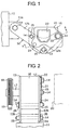
- brackets 12, 13, which are designed as a pair of fixture members, are securely clamped at their mounting plate portions 12b, 13b to opposed lateral surfaces of a mounting portion 11a of a cylinder block 11 by means of bolts 14 and nuts 15.
- Each of the brackets 12, 13 is formed in the shape of L and composed of the mounting plate portion 12b (only the side of the bracket 12 is shown in Fig. 1) and a support plate portion 12a which is provided on the tip end side to serve as a support portion (only the side of the bracket 12 is shown in Fig. 1).
- An oil pump 16 is sandwiched between the brackets 12, 13 and securely mounted by using nuts 15 to clamp a pair of bolts 14 inserted through the mounting plate portion 12b of the bracket 12.
- an input shaft 17 protrudes from the lateral surface of one of the brackets 13 (on the left side in Fig. 2), and a pulley 18 is fixed to the input shaft 17.
- an exhaust pipe 20 designed as a heat source mounted to an engine is disposed on the other side of the pulley.
- a generally rectangular thermal shield 21 formed of an elastic metal plate is fixed to the support plate portion 12a of the bracket 12 and arranged to cover the lateral surface of the oil pump 16 on the side of the exhaust pipe 20. As shown in Fig. 3, the thermal shield 21 is generally downturned from one diagonal end (hereinafter referred to as a mounting end) to the other diagonal end.
- a mounting concave portion 22, a reinforcing concave portion 23, and an engaging protrusion portion 24 designed as a positioning portion and a protrusion portion are press-molded towards the bracket 12 in the mounting end, a central portion, and the other end of the thermal shield 21 respectively.
- the mounting concave portion 22 of the thermal shield 21 is formed in the shape of a closed-end cylinder.
- the tip end of the engaging protrusion portion 24 of the thermal shield 21 is formed in the shape of a hemisphere.
- the engaging protrusion portion 24 is engaged into a positioning hole 27 which is provided in the mounting plate portion 12b of the bracket 12 and which is designed as a positioning portion and a concave portion having a circular cross-section.
- An outer periphery of the spherical surface of the engaging protrusion portion 24 is in line contact with a peripheral edge of the positioning hole 27. That is, the positioning hole 27 is slightly smaller in diameter than the tip end of the engaging protrusion portion 24.
- the entire thermal shield 21 is bent as described above.
- a portion of the thermal shield 21 which contacts the positioning hole 27 of the engaging protrusion portion 24 is offset from the mounting concave portion 22 by the length of a.
- the thermal shield 21 is securely clamped to the bracket 12 by means of the bolt 14. Thereby the engaging protrusion portion 24 is engaged into the positioning hole 27 against an elastic force of the thermal shield 21 and stopped in the positioning hole 27.
- the offset amount is reduced.
- the thermal shield 21 itself that has been bent as described above constitutes pre-load application means.
- the thermal shield 21 is spaced apart from the bracket 12. In other words, there is a clearance formed between the thermal shield 21 and the bracket 12.
- the thermal shield 21 is mounted to the support plate portion 12a of the bracket 12
- the thermal shield 21 is positioned such that the engaging protrusion portion 24 is engaged into the positioning hole 27.
- the bolt 14 is then inserted through the through-hole 22a in the mounting concave portion 22, and the thermal shield 21 is securely clamped to the support plate portion 12a of the bracket 12 by the bolt 14.
- the thermal shield 21 that has been downturned is elastically deformed, and a pre-load is applied to the engaging protrusion portion 24 towards the positioning hole 27.
- the thermal shield 21 is prevented from rotating integrally when tightening the bolt. As a result, the thermal shield 21 is securely clamped to a predetermined position.
- the engaging protrusion portion 24 is formed in the shape of a hemisphere, the engaging protrusion portion 24 is centered without being disengaged from the positioning hole 27 due to application of the pre-load.
- the engaging protrusion portion 24 is engaged into the positioning hole 27 with a pressure being applied to the peripheral edge thereof.
- the hemispherical engaging protrusion portion 24 to which a pre-load is applied is surely engaged with the peripheral edge of the positioning hole 27 and substantially integrated therewith. Accordingly, the engaging protrusion portion 24 is prevented from being disengaged from the positioning hale 27, and generation of chatter (chattering vibrations or chattering noise) in the thermal shield 21 is prevented.
- thermal shield 21 and the bracket 12 are in contact with each other only at the bottom surface of the mounting concave portion 22 and at a portion of the engaging protrusion portion 24 which abuts on the positioning hole 27. Therefore, radiant heat from the exhaust pipe 20 is unlikely to be transmitted to the oil pump 16. Thus, the temperature of hydraulic fluid in the oil pump 16 is inhibited from rising.
- a thermal shield for preventing radiant heat from an exhaust pipe from being transmitted to an oil pump is securely clamped to a support plate portion of a bracket which is disposed contiguous to the thermal shield.
- the thermal shield and the bracket are provided with an engaging protrusion portion and a positioning hole respectively.
- the thermal shield and the bracket are positioned through engagement of the engaging protrusion portion with the positioning hole.
Landscapes
- Engineering & Computer Science (AREA)
- Chemical & Material Sciences (AREA)
- Combustion & Propulsion (AREA)
- Transportation (AREA)
- Mechanical Engineering (AREA)
- Details Of Reciprocating Pumps (AREA)
- Details And Applications Of Rotary Liquid Pumps (AREA)
- Structures Of Non-Positive Displacement Pumps (AREA)
Abstract
Description
Claims (5)
- A mounting structure of a thermal shield for an oil pump, wherein:the thermal shield which is disposed between the oil pump and a heat source and which prevents radiant heat from the heat source from being transmitted to the oil pump is mounted to a support portion;the thermal shield is securely mounted at one point to the support portion;a fixture member disposed contiguous to the thermal shield and the thermal shield are provided with positioning portions and are engaged with each other to be positioned at the positioning portions.
- The mounting structure according to claim 1, wherein:the positioning portion of the fixture member and the positioning portion of the thermal shield are engaged with each other with a pre-load being applied thereto by pre-load application means which is provided at one of the positioning portions.
- The mounting structure according to claim 2, wherein:one of the positioning portions of the fixture member and the thermal shield is a concave portion, and the other is a protrusion portion which is engaged into the concave portion.
- The mounting structure according to claim 3, wherein:the protrusion portion engaged into the concave portion abuts on a peripheral edge of the concave portion.
- The mounting structure according to claim 2, wherein:the pre-load application means is elasticity of the thermal shield itself.
Applications Claiming Priority (2)
| Application Number | Priority Date | Filing Date | Title |
|---|---|---|---|
| JP21651999 | 1999-07-30 | ||
| JP21651999A JP3709745B2 (en) | 1999-07-30 | 1999-07-30 | Heat shield plate mounting structure for oil pump |
Publications (3)
| Publication Number | Publication Date |
|---|---|
| EP1072499A2 true EP1072499A2 (en) | 2001-01-31 |
| EP1072499A3 EP1072499A3 (en) | 2001-05-30 |
| EP1072499B1 EP1072499B1 (en) | 2004-03-31 |
Family
ID=16689715
Family Applications (1)
| Application Number | Title | Priority Date | Filing Date |
|---|---|---|---|
| EP00116420A Expired - Lifetime EP1072499B1 (en) | 1999-07-30 | 2000-07-28 | Mounting structure of thermal shield for oil pump |
Country Status (5)
| Country | Link |
|---|---|
| US (1) | US6601807B1 (en) |
| EP (1) | EP1072499B1 (en) |
| JP (1) | JP3709745B2 (en) |
| DE (1) | DE60009401T2 (en) |
| TW (1) | TW477756B (en) |
Families Citing this family (4)
| Publication number | Priority date | Publication date | Assignee | Title |
|---|---|---|---|---|
| US7469689B1 (en) * | 2004-09-09 | 2008-12-30 | Jones Daniel W | Fluid cooled supercharger |
| JP2016205198A (en) * | 2015-04-21 | 2016-12-08 | 日立オートモティブシステムズ株式会社 | Pump device |
| CN106585711B (en) * | 2016-12-08 | 2018-07-27 | 安徽江淮汽车集团股份有限公司 | Oil can fixed structure |
| WO2018186203A1 (en) * | 2017-04-04 | 2018-10-11 | パナソニックIpマネジメント株式会社 | Scroll compressor |
Family Cites Families (4)
| Publication number | Priority date | Publication date | Assignee | Title |
|---|---|---|---|---|
| DE8700918U1 (en) * | 1987-01-21 | 1987-03-05 | H.W. Meckenstock KG, 4020 Mettmann | Heat shield |
| JPH07102965A (en) * | 1993-10-08 | 1995-04-18 | Toyota Motor Corp | Exhaust manifold mounting structure |
| DE19623996C2 (en) * | 1996-06-15 | 1999-05-12 | Daimler Benz Ag | Shield plate for an exhaust pipe and exhaust pipe with such a shield plate |
| JP3803986B2 (en) * | 1997-03-21 | 2006-08-02 | カルソニックカンセイ株式会社 | Two-panel simultaneous drawing method for hollow panel-shaped product material, press apparatus used therefor, and method for manufacturing hollow insulator |
-
1999
- 1999-07-30 JP JP21651999A patent/JP3709745B2/en not_active Expired - Fee Related
-
2000
- 2000-07-28 EP EP00116420A patent/EP1072499B1/en not_active Expired - Lifetime
- 2000-07-28 DE DE60009401T patent/DE60009401T2/en not_active Expired - Fee Related
- 2000-07-31 US US09/629,625 patent/US6601807B1/en not_active Expired - Fee Related
- 2000-10-23 TW TW089115339A patent/TW477756B/en not_active IP Right Cessation
Also Published As
| Publication number | Publication date |
|---|---|
| EP1072499B1 (en) | 2004-03-31 |
| US6601807B1 (en) | 2003-08-05 |
| JP2001041170A (en) | 2001-02-13 |
| EP1072499A3 (en) | 2001-05-30 |
| JP3709745B2 (en) | 2005-10-26 |
| TW477756B (en) | 2002-03-01 |
| DE60009401T2 (en) | 2005-03-17 |
| DE60009401D1 (en) | 2004-05-06 |
Similar Documents
| Publication | Publication Date | Title |
|---|---|---|
| JP3503405B2 (en) | Anti-vibration device | |
| US6564913B2 (en) | Brake disk/hub assembly for vehicle disk brakes | |
| US20010016529A1 (en) | Mechanical device for transmitting power | |
| CN100473861C (en) | Rubber bearing for a motor pump unit of a power steering system | |
| JPWO2002030694A1 (en) | Strut mount | |
| CN112319249A (en) | Power battery and tolerance compensation unit for an electrically operated vehicle | |
| JP2002510260A (en) | Motor drive | |
| CN111853230B (en) | Rotary actuator | |
| US6601807B1 (en) | Mounting structure of thermal shield for oil pump | |
| JP2001159406A (en) | Installing structure using nut and bolt | |
| JPH11257397A (en) | Vibration isolating device | |
| EP0961014B1 (en) | Resilient support device for the exhaust pipe of a vehicle | |
| CN101283185B (en) | Fixtures for securing automotive components | |
| JPH08326811A (en) | Vibration control device | |
| JP2024519224A (en) | Drive unit and vehicle | |
| JP2002174289A (en) | Damping bolt and fastening structure with vibration damping function | |
| JP2001027285A (en) | Power plant mounting device | |
| JPH1159337A (en) | Vehicular part and structure for installing the same | |
| CN221004483U (en) | Motor controller installation structure, power system and vehicle | |
| JPH09119425A (en) | Screwing structure for fitted object | |
| JPH0379204B2 (en) | ||
| RU2126748C1 (en) | Vehicle clutch drive cylinder fastening device | |
| JPH057072Y2 (en) | ||
| KR100210304B1 (en) | Engine mounting for a vehicle | |
| KR0126171Y1 (en) | Heat deflector of engine mount for automobiles |
Legal Events
| Date | Code | Title | Description |
|---|---|---|---|
| PUAI | Public reference made under article 153(3) epc to a published international application that has entered the european phase |
Free format text: ORIGINAL CODE: 0009012 |
|
| AK | Designated contracting states |
Kind code of ref document: A2 Designated state(s): DE FR GB |
|
| AX | Request for extension of the european patent |
Free format text: AL;LT;LV;MK;RO;SI |
|
| PUAL | Search report despatched |
Free format text: ORIGINAL CODE: 0009013 |
|
| AK | Designated contracting states |
Kind code of ref document: A3 Designated state(s): AT BE CH CY DE DK ES FI FR GB GR IE IT LI LU MC NL PT SE |
|
| AX | Request for extension of the european patent |
Free format text: AL;LT;LV;MK;RO;SI |
|
| 17P | Request for examination filed |
Effective date: 20011130 |
|
| AKX | Designation fees paid |
Free format text: DE FR GB |
|
| GRAP | Despatch of communication of intention to grant a patent |
Free format text: ORIGINAL CODE: EPIDOSNIGR1 |
|
| GRAS | Grant fee paid |
Free format text: ORIGINAL CODE: EPIDOSNIGR3 |
|
| GRAA | (expected) grant |
Free format text: ORIGINAL CODE: 0009210 |
|
| AK | Designated contracting states |
Kind code of ref document: B1 Designated state(s): DE FR GB |
|
| REG | Reference to a national code |
Ref country code: GB Ref legal event code: FG4D |
|
| REF | Corresponds to: |
Ref document number: 60009401 Country of ref document: DE Date of ref document: 20040506 Kind code of ref document: P |
|
| ET | Fr: translation filed | ||
| PLBE | No opposition filed within time limit |
Free format text: ORIGINAL CODE: 0009261 |
|
| STAA | Information on the status of an ep patent application or granted ep patent |
Free format text: STATUS: NO OPPOSITION FILED WITHIN TIME LIMIT |
|
| 26N | No opposition filed |
Effective date: 20050104 |
|
| PGFP | Annual fee paid to national office [announced via postgrant information from national office to epo] |
Ref country code: GB Payment date: 20080806 Year of fee payment: 9 |
|
| PGFP | Annual fee paid to national office [announced via postgrant information from national office to epo] |
Ref country code: FR Payment date: 20090710 Year of fee payment: 10 |
|
| PGFP | Annual fee paid to national office [announced via postgrant information from national office to epo] |
Ref country code: DE Payment date: 20090723 Year of fee payment: 10 |
|
| GBPC | Gb: european patent ceased through non-payment of renewal fee |
Effective date: 20090728 |
|
| PG25 | Lapsed in a contracting state [announced via postgrant information from national office to epo] |
Ref country code: GB Free format text: LAPSE BECAUSE OF NON-PAYMENT OF DUE FEES Effective date: 20090728 |
|
| REG | Reference to a national code |
Ref country code: FR Ref legal event code: ST Effective date: 20110331 |
|
| PG25 | Lapsed in a contracting state [announced via postgrant information from national office to epo] |
Ref country code: DE Free format text: LAPSE BECAUSE OF NON-PAYMENT OF DUE FEES Effective date: 20110201 |
|
| REG | Reference to a national code |
Ref country code: DE Ref legal event code: R119 Ref document number: 60009401 Country of ref document: DE Effective date: 20110201 |
|
| PG25 | Lapsed in a contracting state [announced via postgrant information from national office to epo] |
Ref country code: FR Free format text: LAPSE BECAUSE OF NON-PAYMENT OF DUE FEES Effective date: 20100802 |