EP1072464A1 - Vehicle occupant protection system - Google Patents
Vehicle occupant protection system Download PDFInfo
- Publication number
- EP1072464A1 EP1072464A1 EP00116055A EP00116055A EP1072464A1 EP 1072464 A1 EP1072464 A1 EP 1072464A1 EP 00116055 A EP00116055 A EP 00116055A EP 00116055 A EP00116055 A EP 00116055A EP 1072464 A1 EP1072464 A1 EP 1072464A1
- Authority
- EP
- European Patent Office
- Prior art keywords
- seat
- vehicle
- vehicle body
- vehicle occupant
- protection system
- Prior art date
- Legal status (The legal status is an assumption and is not a legal conclusion. Google has not performed a legal analysis and makes no representation as to the accuracy of the status listed.)
- Granted
Links
- 230000007246 mechanism Effects 0.000 claims abstract description 14
- 238000006073 displacement reaction Methods 0.000 claims description 5
- 230000004913 activation Effects 0.000 claims description 2
- 239000003380 propellant Substances 0.000 claims description 2
- 230000001133 acceleration Effects 0.000 abstract description 7
- 239000007789 gas Substances 0.000 description 10
- 230000000452 restraining effect Effects 0.000 description 3
- 238000006243 chemical reaction Methods 0.000 description 2
- 230000006835 compression Effects 0.000 description 2
- 238000007906 compression Methods 0.000 description 2
- 230000003213 activating effect Effects 0.000 description 1
- 230000004075 alteration Effects 0.000 description 1
- 238000013459 approach Methods 0.000 description 1
- 239000000567 combustion gas Substances 0.000 description 1
- 230000000295 complement effect Effects 0.000 description 1
- 230000000694 effects Effects 0.000 description 1
- 230000005489 elastic deformation Effects 0.000 description 1
- 239000002360 explosive Substances 0.000 description 1
- 238000000034 method Methods 0.000 description 1
- 238000012986 modification Methods 0.000 description 1
- 230000004048 modification Effects 0.000 description 1
- 230000008569 process Effects 0.000 description 1
- 230000000717 retained effect Effects 0.000 description 1
- 230000002441 reversible effect Effects 0.000 description 1
- 230000000630 rising effect Effects 0.000 description 1
- 230000002459 sustained effect Effects 0.000 description 1
Images


Classifications
-
- B—PERFORMING OPERATIONS; TRANSPORTING
- B60—VEHICLES IN GENERAL
- B60N—SEATS SPECIALLY ADAPTED FOR VEHICLES; VEHICLE PASSENGER ACCOMMODATION NOT OTHERWISE PROVIDED FOR
- B60N2/00—Seats specially adapted for vehicles; Arrangement or mounting of seats in vehicles
- B60N2/24—Seats specially adapted for vehicles; Arrangement or mounting of seats in vehicles for particular purposes or particular vehicles
- B60N2/42—Seats specially adapted for vehicles; Arrangement or mounting of seats in vehicles for particular purposes or particular vehicles the seat constructed to protect the occupant from the effect of abnormal g-forces, e.g. crash or safety seats
- B60N2/427—Seats or parts thereof displaced during a crash
- B60N2/42772—Seats or parts thereof displaced during a crash characterised by the triggering system
- B60N2/42781—Seats or parts thereof displaced during a crash characterised by the triggering system mechanical triggering
-
- B—PERFORMING OPERATIONS; TRANSPORTING
- B60—VEHICLES IN GENERAL
- B60N—SEATS SPECIALLY ADAPTED FOR VEHICLES; VEHICLE PASSENGER ACCOMMODATION NOT OTHERWISE PROVIDED FOR
- B60N2/00—Seats specially adapted for vehicles; Arrangement or mounting of seats in vehicles
- B60N2/24—Seats specially adapted for vehicles; Arrangement or mounting of seats in vehicles for particular purposes or particular vehicles
- B60N2/42—Seats specially adapted for vehicles; Arrangement or mounting of seats in vehicles for particular purposes or particular vehicles the seat constructed to protect the occupant from the effect of abnormal g-forces, e.g. crash or safety seats
- B60N2/4207—Seats specially adapted for vehicles; Arrangement or mounting of seats in vehicles for particular purposes or particular vehicles the seat constructed to protect the occupant from the effect of abnormal g-forces, e.g. crash or safety seats characterised by the direction of the g-forces
- B60N2/4214—Seats specially adapted for vehicles; Arrangement or mounting of seats in vehicles for particular purposes or particular vehicles the seat constructed to protect the occupant from the effect of abnormal g-forces, e.g. crash or safety seats characterised by the direction of the g-forces longitudinal
- B60N2/4221—Seats specially adapted for vehicles; Arrangement or mounting of seats in vehicles for particular purposes or particular vehicles the seat constructed to protect the occupant from the effect of abnormal g-forces, e.g. crash or safety seats characterised by the direction of the g-forces longitudinal due to impact coming from the front
-
- B—PERFORMING OPERATIONS; TRANSPORTING
- B60—VEHICLES IN GENERAL
- B60N—SEATS SPECIALLY ADAPTED FOR VEHICLES; VEHICLE PASSENGER ACCOMMODATION NOT OTHERWISE PROVIDED FOR
- B60N2/00—Seats specially adapted for vehicles; Arrangement or mounting of seats in vehicles
- B60N2/24—Seats specially adapted for vehicles; Arrangement or mounting of seats in vehicles for particular purposes or particular vehicles
- B60N2/42—Seats specially adapted for vehicles; Arrangement or mounting of seats in vehicles for particular purposes or particular vehicles the seat constructed to protect the occupant from the effect of abnormal g-forces, e.g. crash or safety seats
- B60N2/427—Seats or parts thereof displaced during a crash
- B60N2/42727—Seats or parts thereof displaced during a crash involving substantially rigid displacement
- B60N2/42736—Seats or parts thereof displaced during a crash involving substantially rigid displacement of the whole seat
Definitions
- the present invention relates to a vehicle occupant protection system, and in particular to a vehicle occupant protection system which can reduce a deceleration acting upon a vehicle occupant at the time of a vehicle crash.
- the maximum deceleration level increases as the forward movement of the vehicle occupant with respect to the vehicle body under the inertia force increases, and is known to substantially exceed the average deceleration of the vehicle body. Therefore, in order to minimize the impact which the vehicle occupant receives at the time of a vehicle crash, it is necessary to minimize the time delay in the rise in the deceleration of the vehicle occupant with respect to the deceleration of the vehicle body and thereby reduce the forward movement of the vehicle occupant with respect to the vehicle body.
- a primary object of the present invention is to provide a vehicle occupant protection system which allows the peak deceleration acting upon a vehicle occupant at the time of a vehicle crash to be minimized for a given deformation stroke of the vehicle body.
- a second object of the present invention is to provide a vehicle occupant protection system which allows the deceleration acting upon the vehicle occupant at the time of a vehicle crash to be spread over time so as to minimize the peak deceleration acting upon the vehicle occupant.
- a third object of the present invention is to provide a vehicle occupant protection system which allows the peak deceleration acting upon the vehicle occupant to be minimized even though the size of the vehicle body is limited.
- a fourth object of the present invention is to provide a vehicle occupant protection system which is simple in structure, and light in weight.
- a vehicle occupant protection system comprising: a seat which is fitted with a seat belt, and supported on a vehicle body so as to be slidable in a direction of an input crash load resulting from a vehicle crash; a crash sensor mounted on the vehicle body for detecting a vehicle crash; a power actuator fixedly attached to the vehicle body, and adapted to apply a rearward force to the seat upon occurrence of a vehicle crash; a stopper member fixedly attached to the vehicle body and adapted to stop a rearward movement of the seat produced by the power actuator following a prescribed rearward displacement of the seat; and a one-way motion mechanism for permitting the rearward movement of the seat, but prohibiting any forward movement of the seat after the stopper has stopped the rearward movement of the seat.
- the seat is subjected to a forward deceleration by the power actuator substantially without any time delay, and following a rearward movement of the seat with respect to the vehicle body by a prescribed distance, the seat is subjected to a forward acceleration to prevent any excessive rise in the forward deceleration of the vehicle occupant. Thereafter, the vehicle seat is required to move substantially integrally with the vehicle body, and the one-way motion mechanism ensures the vehicle seat to move jointly with the vehicle body once the stopper has stopped the rearward movement of the seat.
- the one-way motion mechanism may comprise a first part attached to the seat and a second part attached to the vehicle body, at least one of the parts being provided with a slope engaged by the other of the parts, and at least one of the parts being resiliently supported by a corresponding one of the seat and vehicle body to accommodate a relative displacement between the two parts in a direction different from that resulting from a rearward movement of the seat.
- the one-way motion mechanism can be made of a simple structure, and adapted to reliable operation.
- a ratchet mechanism can be conveniently used for such a purpose.
- the one-way motion mechanism may comprise a first part attached to the seat and a second part attached to the vehicle body, the first part and second part being positioned in a spaced relationship from each other before activation of the power actuator, and adapted to engaged and lock with each other simultaneously as the stopper has stopped the rearward movement of the seat.
- a latch mechanism or similar arrangement using plastic and/or elastic deformation of at least one member for irreversibly joining one member to another as the two member come together.
- the power actuator may consist of any actuator which is capable of activating adequately promptly with a required power output.
- a piston/cylinder arrangement using a pyrotechnic is suited for such a purpose.
- the crash sensor may consist of a limit switch or a stress sensor for detecting the deformation of a vehicle body part.
- an acceleration sensor such as those widely used in association with air bag occupant restraint system may also be used.
- a radar or laser sensor for detecting a crash before it actually happens can also be used for this purpose.
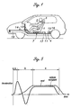
- FIG. 1 schematically illustrates a vehicle incorporated with a vehicle occupant protection system embodying the present invention.
- the seat 1 To restrain movement of a vehicle occupant 2 with respect to a seat 1, the seat 1 is fitted with a seat belt 3.
- the anchor points of the seat 1 may be all provided in the seat 1, or only a part of the anchor points of the seat 1 may be provided in the seat 1 while the remaining anchor points are provided in fixed parts of the vehicle body.
- the seat 1 is mounted on a support base 6 slidably engaged by guide rails 5 as illustrated in Figure 2 so as to be moveable over a certain distance along the fore-and-aft direction of the vehicle body with respect to a floor 4 defining a passenger compartment of the vehicle body.
- the actuator 7 for producing a drive force for moving the seat 1, along with the support base 6, rearwardly along the guide rails 5.
- the actuator 7 comprises a cylinder 8 fixedly attached to the floor 4, a piston 9 slidably received in the cylinder 8, a piston rod 11 connecting the support base 6 and the piston 9 with each other, and a gas generator 12 for producing high pressure gas and applying a drive force to the piston 9.
- the gas generator 12 is electrically connected to a control unit 13, and can produce high pressure combustion gas by igniting a propellant received therein with electric current from the control unit 13.
- the control unit 13 supplies ignition current to the gas generator 12 upon detecting a vehicle crash from a signal of a deceleration sensor 14 placed in a suitable part of the vehicle body.
- a stopper 15 is provided in a part of the floor 4 behind the seat 1 to limit the rearward movement of the seat 1 to be within a prescribed distance. It is also possible to provide a stopper structure in the top end of the cylinder inside the actuator 7 to achieve a similar result.
- the illustrated stopper 15 consists of a plate member which projects from a front face of a rigid wall section 16 which stands upright integrally from the floor 4.
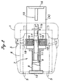
- a pair of moveable clamp members 17 are provided on either side of the piston rod 11. As best shown in Figure 2, the moveable clamp members 17 are disposed on either lateral side of the piston rod 11, and are received in corresponding clamp member guides 18 which are fixedly attached to the floor 4 of the vehicle body, and guide the corresponding clamp members 17 for movement in a direction perpendicular to the axial line of the piston rod 11. Compression coil springs 19 received in the clamp member guides 18 resiliently urge the clamp members 17 toward the piston rod 11.
- the piston rod 11 and each of the moveable clamp members 17 engage each other via a teeth section 11a and a pawl section 17a provided in the piston rod 11 and clamp member 17, respectively, as best shown in Figure 3.
- the engagement teeth section 11a and the pawl section 17a are provided with complementary shapes at the interface in such a manner that the slope on each teeth of the engagement teeth section 11a faces rearward with respect to the vehicle body, and the slope on each pawl of the pawl section 17a faces forward with respect to the vehicle body.
- the vertical side of each teeth of the engagement teeth section 11a (a plane extending perpendicularly to the axial line of the piston rod 11) and the vertical side of each pawl of the pawl section 17 are adapted to engage each other.
- a pair of side beams 16 which are integral with the floor 4 and extend in the forward direction start a compressive deformation under an impact load applied to the front ends thereof.
- the floor 4 continues to move forward by a stroke accommodated by the compression of the side beams 16 while receiving a deceleration due to the deformation stress produced in the side beams 16.
- the support base 6 connected to the piston 9 via the piston rod 11, hence the seat 1 is subjected to a rearward acceleration or a deceleration in the direction of the crash impact load, and the seat 1 starts moving rearward with respect to the floor 4. Therefore, a deceleration of a higher level than that applied to the floor 4 or the passenger compartment of the vehicle body is applied to the seat 1 (interval a of Figure 5).
- the vehicle occupant 2 tends to move forward under the inertia force with respect to the vehicle body which is coming to a stop.
- the seat belt 3 which is integral with the seat 1 instantaneously restrains the vehicle occupant to the seat 1 substantially without creating any relative speed between the vehicle occupant 2 and the floor 4.
- the projecting end 11b of the piston rod 11 abuts the stopper 15, and a reaction load due to the resultant plastic deformation of the stopper 15 decelerates the piston 9.
- the projecting end 11b is U-shaped with an open end thereof facing the stopper 15 so that the projecting end 11b catches the stopper 15 at the time of the crash, and the two parts can be held in the mutually abutting state without fail.
- the deceleration of the seat 1 again rises sharply upon completion of the operation of the actuator 7 (piston rod 11) (later part of interval b of Figure 5), and the deceleration continues with the seat 1 integrally attached to the floor 4 at a deceleration level determined by the deformation stress of the side beams 19.
- the relative speed between the vehicle occupant 2 and the floor 4 is zero, and because the restraining load of the seat belt 3 balances out with the vehicle body deceleration during the final phase of the crash, the vehicle occupant 2 continues to decelerate, integrally with the floor 4 (interval c of Figure 5). Under this condition, the vehicle occupant deceleration is equal to the vehicle body deceleration until the vehicle body comes to a complete stop.
- the vehicle occupant deceleration can be reduced from the level of the prior art if the time history of deceleration is controlled (as indicated by the solid lines in Figure 5) in such a manner that a deceleration which is higher than the average vehicle body deceleration is applied to the seat 1 and the seat belt 3 for a short period of time during an early phase of a vehicle crash, and following a short interval of applying a reverse deceleration to the seat 1 and the seat belt 3, a same deceleration as the average vehicle body deceleration is applied to the seat 1 and the seat belt 3.
- the mechanical strength of the side beams 19, the resilient property of the seat belt 3, and the output property and the ignition timing of the actuator 7 so as to bring the relative speed between the vehicle occupant 2 and the floor 4 as close to zero as possible, and to balance out the restraining load of the seat belt 3 with the vehicle body deceleration during the final phase of the crash when the relative speed between the seat 1 and the floor 4 is reduced to zero and the deceleration levels of these two parts have been brought equal to each other.
- interval c of Figure 5 it is preferable to allow the seat 1 to decelerate jointly with the floor 4 following the rearward displacement of the seat 1. To this end, the forward movement of the piston rod 11 which is integral with the seat 1 is prohibited.
- the pair of moveable clamp members 17 resiliently clamp the piston rod 11 under normal condition.
- the rearward movement of the seat 1 is permitted owing to the prescribed shapes of the engagement teeth section 11a and the pawl section 17a as mentioned earlier. More specifically, as the seat 1 moves rearward, and the piston rod 11 moves in the direction indicated by arrow A in Figure 4a, the slopes of the teeth and pawl of the engagement teeth section 11a and pawl section 17a abut each other, and the slopes of the teeth of the engagement teeth section 11a ride over the slopes of the pawls of the pawl section 17a so that the two clamp members 17 are pushed away from each other against the resilient biasing force as indicated by arrow B, and the piston rod 11 can move rearward.
- the seat 1 was directly mounted on the piston rod 11 in the above described embodiment, but a separate frame supporting the seat 1 may be connected to a working end of the actuator 7 such as the piston rod 11.
- the bifurcated end 11b of the piston rod 11 may be replaced with any known arrangement for latching the piston rod or a member connected thereto with a fixed part of the vehicle body upon abutment.
- the arrangement using the engagement teeth section 11a and the pawl section 17a is only an example of the one-way motion mechanism, and may consist of any per se known arrangement for permitting the relative motion only in one direction.
- the seat is subjected to a forward deceleration by a power actuator following a frontal vehicle crash substantially without any time delay, and following a rearward movement of the seat with respect to the vehicle body by a prescribed distance, the seat is subjected to a forward acceleration by a stopper attached to a vehicle body to prevent any excessive rise in the forward deceleration of the vehicle occupant. Thereafter, the vehicle seat is required to move substantially integrally with the vehicle body to allow the vehicle occupant to decelerate at a tolerable deceleration level by virtue of a controlled deformation of the vehicle body, and the one-way motion mechanism ensures the vehicle seat to move jointly with the vehicle body once the stopper has stopped the rearward movement of the seat.
Landscapes
- Engineering & Computer Science (AREA)
- Aviation & Aerospace Engineering (AREA)
- Transportation (AREA)
- Mechanical Engineering (AREA)
- Seats For Vehicles (AREA)
- Automotive Seat Belt Assembly (AREA)
Abstract
Description
- The present invention relates to a vehicle occupant protection system, and in particular to a vehicle occupant protection system which can reduce a deceleration acting upon a vehicle occupant at the time of a vehicle crash.
- In recent years, various proposals have been made in regard to automotive vehicle body structures to maximize the protection of vehicle occupants at the time of a vehicle crash. For instance, proposals have been made to minimize the deceleration of the part of the vehicle body occupied by vehicle occupants by properly selecting the deformation of the remaining part of the vehicle body, and preventing the former part of the vehicle body from deforming (see Japanese patent laid open publication No. 7-101354, for instance).
- However, it may be difficult to reduce the deceleration of the vehicle occupant in the case of small cars which do not provide adequate deformation strokes of the parts of the vehicle body other than the part occupied by the vehicle occupant only with such conventional approaches which essentially consist of attempts to reduce the deceleration of the passenger compartment by controlling the deformation mode of the vehicle body.
- Further, it is generally impossible to integrally hold a vehicle occupant to a vehicle body even if the seat is fixedly attached to the vehicle body because the seat belt for restraining the vehicle occupant to the seat has an inevitable slack. Thus, when a vehicle crash occurs, the forward inertia force acting upon the vehicle occupant at the time of a vehicle crash starts rising only after the vehicle occupant is fully restrained by the seat belt. Further, because the seat belt inevitably has a certain resiliency, the deceleration acting on the vehicle occupant, who tends to continue to move forward, reaches a maximum level only when the maximum elongation of the seat belt takes place. The maximum deceleration level increases as the forward movement of the vehicle occupant with respect to the vehicle body under the inertia force increases, and is known to substantially exceed the average deceleration of the vehicle body. Therefore, in order to minimize the impact which the vehicle occupant receives at the time of a vehicle crash, it is necessary to minimize the time delay in the rise in the deceleration of the vehicle occupant with respect to the deceleration of the vehicle body and thereby reduce the forward movement of the vehicle occupant with respect to the vehicle body.
- Proposals have been made in copending US patent application Nos. 09/377,366 and 09/376,888 both filed on August 18, 1999, to impart a relative deceleration and acceleration to the vehicle seat or the member carrying the vehicle seat with respect to the main part of the vehicle body so that the vehicle occupant may experience a deceleration from an early stage of a vehicle crash, and the maximum vehicle occupant deceleration may be reduced by distributing the inertia force acting on the vehicle occupant over a longer period of time. There are additional copending US patent applications of later filing dates which also relate to similar subject matters. The contents of these applications are hereby incorporated in this application by reference.
- In view of such problems of the prior art and the recognition by the inventors, a primary object of the present invention is to provide a vehicle occupant protection system which allows the peak deceleration acting upon a vehicle occupant at the time of a vehicle crash to be minimized for a given deformation stroke of the vehicle body.
- A second object of the present invention is to provide a vehicle occupant protection system which allows the deceleration acting upon the vehicle occupant at the time of a vehicle crash to be spread over time so as to minimize the peak deceleration acting upon the vehicle occupant.
- A third object of the present invention is to provide a vehicle occupant protection system which allows the peak deceleration acting upon the vehicle occupant to be minimized even though the size of the vehicle body is limited.
- A fourth object of the present invention is to provide a vehicle occupant protection system which is simple in structure, and light in weight.
- According to the present invention, such objects can be accomplished by providing a vehicle occupant protection system, comprising: a seat which is fitted with a seat belt, and supported on a vehicle body so as to be slidable in a direction of an input crash load resulting from a vehicle crash; a crash sensor mounted on the vehicle body for detecting a vehicle crash; a power actuator fixedly attached to the vehicle body, and adapted to apply a rearward force to the seat upon occurrence of a vehicle crash; a stopper member fixedly attached to the vehicle body and adapted to stop a rearward movement of the seat produced by the power actuator following a prescribed rearward displacement of the seat; and a one-way motion mechanism for permitting the rearward movement of the seat, but prohibiting any forward movement of the seat after the stopper has stopped the rearward movement of the seat.
- Thus, the seat is subjected to a forward deceleration by the power actuator substantially without any time delay, and following a rearward movement of the seat with respect to the vehicle body by a prescribed distance, the seat is subjected to a forward acceleration to prevent any excessive rise in the forward deceleration of the vehicle occupant. Thereafter, the vehicle seat is required to move substantially integrally with the vehicle body, and the one-way motion mechanism ensures the vehicle seat to move jointly with the vehicle body once the stopper has stopped the rearward movement of the seat.
- The one-way motion mechanism may comprise a first part attached to the seat and a second part attached to the vehicle body, at least one of the parts being provided with a slope engaged by the other of the parts, and at least one of the parts being resiliently supported by a corresponding one of the seat and vehicle body to accommodate a relative displacement between the two parts in a direction different from that resulting from a rearward movement of the seat. Thereby, the one-way motion mechanism can be made of a simple structure, and adapted to reliable operation. A ratchet mechanism can be conveniently used for such a purpose.
- Additionally and/or alternatively, the one-way motion mechanism may comprise a first part attached to the seat and a second part attached to the vehicle body, the first part and second part being positioned in a spaced relationship from each other before activation of the power actuator, and adapted to engaged and lock with each other simultaneously as the stopper has stopped the rearward movement of the seat. For such a purpose, a latch mechanism or similar arrangement using plastic and/or elastic deformation of at least one member for irreversibly joining one member to another as the two member come together.
- The power actuator may consist of any actuator which is capable of activating adequately promptly with a required power output. A piston/cylinder arrangement using a pyrotechnic is suited for such a purpose. The crash sensor may consist of a limit switch or a stress sensor for detecting the deformation of a vehicle body part. Alternatively, an acceleration sensor such as those widely used in association with air bag occupant restraint system may also be used. If desired, a radar or laser sensor for detecting a crash before it actually happens can also be used for this purpose.
- Now the present invention is described in the following with reference to the appended drawings, in which:
- Figure 1 is a schematic side view of a vehicle body incorporated with a vehicle occupant protection system embodying the present invention;
- Figure 2 is a partly broken away enlarged plan view of the vehicle occupant protection system;
- Figure 3 is an enlarged view showing a part of Figure 2;
- Figures 4a and 4b are views similar to Figure 3 showing the mode of operation of the one-way motion mechanism; and
- Figure 5 is a graph showing the time histories of deceleration at the time of the vehicle crash.
-
- Figure 1 schematically illustrates a vehicle incorporated with a vehicle occupant protection system embodying the present invention. To restrain movement of a vehicle occupant 2 with respect to a
seat 1, theseat 1 is fitted with aseat belt 3. The anchor points of theseat 1 may be all provided in theseat 1, or only a part of the anchor points of theseat 1 may be provided in theseat 1 while the remaining anchor points are provided in fixed parts of the vehicle body. Theseat 1 is mounted on asupport base 6 slidably engaged byguide rails 5 as illustrated in Figure 2 so as to be moveable over a certain distance along the fore-and-aft direction of the vehicle body with respect to afloor 4 defining a passenger compartment of the vehicle body. - Under the
seat 1 is disposed anactuator 7 for producing a drive force for moving theseat 1, along with thesupport base 6, rearwardly along theguide rails 5. As also shown in Figure 2, theactuator 7 comprises acylinder 8 fixedly attached to thefloor 4, apiston 9 slidably received in thecylinder 8, apiston rod 11 connecting thesupport base 6 and thepiston 9 with each other, and agas generator 12 for producing high pressure gas and applying a drive force to thepiston 9. - The
gas generator 12 is electrically connected to a control unit 13, and can produce high pressure combustion gas by igniting a propellant received therein with electric current from the control unit 13. The control unit 13 supplies ignition current to thegas generator 12 upon detecting a vehicle crash from a signal of a deceleration sensor 14 placed in a suitable part of the vehicle body. - A
stopper 15 is provided in a part of thefloor 4 behind theseat 1 to limit the rearward movement of theseat 1 to be within a prescribed distance. It is also possible to provide a stopper structure in the top end of the cylinder inside theactuator 7 to achieve a similar result. The illustratedstopper 15 consists of a plate member which projects from a front face of arigid wall section 16 which stands upright integrally from thefloor 4. - A pair of
moveable clamp members 17 are provided on either side of thepiston rod 11. As best shown in Figure 2, themoveable clamp members 17 are disposed on either lateral side of thepiston rod 11, and are received in correspondingclamp member guides 18 which are fixedly attached to thefloor 4 of the vehicle body, and guide thecorresponding clamp members 17 for movement in a direction perpendicular to the axial line of thepiston rod 11.Compression coil springs 19 received in theclamp member guides 18 resiliently urge theclamp members 17 toward thepiston rod 11. - The
piston rod 11 and each of themoveable clamp members 17 engage each other via ateeth section 11a and apawl section 17a provided in thepiston rod 11 andclamp member 17, respectively, as best shown in Figure 3. Theengagement teeth section 11a and thepawl section 17a are provided with complementary shapes at the interface in such a manner that the slope on each teeth of theengagement teeth section 11a faces rearward with respect to the vehicle body, and the slope on each pawl of thepawl section 17a faces forward with respect to the vehicle body. The vertical side of each teeth of theengagement teeth section 11a (a plane extending perpendicularly to the axial line of the piston rod 11) and the vertical side of each pawl of thepawl section 17 are adapted to engage each other. - The mode of operation of the device of the present invention is described in the following by taking an example of a vehicle crashing head-on onto an object on the road with reference to Figures 3 and 4.
- Upon the occurrence of a vehicle crash, a pair of
side beams 16 which are integral with thefloor 4 and extend in the forward direction start a compressive deformation under an impact load applied to the front ends thereof. At this time, thefloor 4 continues to move forward by a stroke accommodated by the compression of theside beams 16 while receiving a deceleration due to the deformation stress produced in theside beams 16. - When the control unit 13 judges that the vehicle occupant protection system should be activated according to the signal from the deceleration sensor 14, electric current is supplied to the
gas generator 12 to ignite the high pressure gas therein. As a result, the high pressure gas produced from thegas generator 12 is supplied to the bottom end of thecylinder 8, and thepiston 9 is pushed rearward under the pressure of the high pressure gas. At this time, the slopes on theteeth section 11a and thepawl section 17a cause theclamp members 17 to be pushed sideways away from thepiston rod 11, and allows thepiston rod 11 to move rearward - As the
piston 9 is pushed out under the pressure of the gas, thesupport base 6 connected to thepiston 9 via thepiston rod 11, hence theseat 1, is subjected to a rearward acceleration or a deceleration in the direction of the crash impact load, and theseat 1 starts moving rearward with respect to thefloor 4. Therefore, a deceleration of a higher level than that applied to thefloor 4 or the passenger compartment of the vehicle body is applied to the seat 1 (interval a of Figure 5). During this process, the vehicle occupant 2 tends to move forward under the inertia force with respect to the vehicle body which is coming to a stop. Because theseat 1 is subjected to a rearward acceleration immediately following the crash, theseat belt 3 which is integral with theseat 1 instantaneously restrains the vehicle occupant to theseat 1 substantially without creating any relative speed between the vehicle occupant 2 and thefloor 4. - Then, the projecting
end 11b of thepiston rod 11 abuts thestopper 15, and a reaction load due to the resultant plastic deformation of thestopper 15 decelerates thepiston 9. The projectingend 11b is U-shaped with an open end thereof facing thestopper 15 so that the projectingend 11b catches thestopper 15 at the time of the crash, and the two parts can be held in the mutually abutting state without fail. - At the same time, because the vertical sides of the teeth and pawls of the
teeth section 11a andpawl section 17a engage each other, thepiston rod 11 is positively prevented from moving forward with respect to theclamp members 17 or the vehicle body. - During a final phase of the crash, the deceleration of the
seat 1 again rises sharply upon completion of the operation of the actuator 7 (piston rod 11) (later part of interval b of Figure 5), and the deceleration continues with theseat 1 integrally attached to thefloor 4 at a deceleration level determined by the deformation stress of the side beams 19. Under this condition, the relative speed between the vehicle occupant 2 and thefloor 4 is zero, and because the restraining load of theseat belt 3 balances out with the vehicle body deceleration during the final phase of the crash, the vehicle occupant 2 continues to decelerate, integrally with the floor 4 (interval c of Figure 5). Under this condition, the vehicle occupant deceleration is equal to the vehicle body deceleration until the vehicle body comes to a complete stop. - It is an important factor to minimize the vehicle occupant deceleration in view of reducing the impact which is sustained by the vehicle occupant 2 at the time of a vehicle crash. However, the vehicle occupant deceleration can be reduced from the level of the prior art if the time history of deceleration is controlled (as indicated by the solid lines in Figure 5) in such a manner that a deceleration which is higher than the average vehicle body deceleration is applied to the
seat 1 and theseat belt 3 for a short period of time during an early phase of a vehicle crash, and following a short interval of applying a reverse deceleration to theseat 1 and theseat belt 3, a same deceleration as the average vehicle body deceleration is applied to theseat 1 and theseat belt 3. - To enhance the effect of the present invention which was described above, it is preferable to suitably select the mechanical strength of the side beams 19, the resilient property of the
seat belt 3, and the output property and the ignition timing of theactuator 7 so as to bring the relative speed between the vehicle occupant 2 and thefloor 4 as close to zero as possible, and to balance out the restraining load of theseat belt 3 with the vehicle body deceleration during the final phase of the crash when the relative speed between theseat 1 and thefloor 4 is reduced to zero and the deceleration levels of these two parts have been brought equal to each other. Also, in interval c of Figure 5, it is preferable to allow theseat 1 to decelerate jointly with thefloor 4 following the rearward displacement of theseat 1. To this end, the forward movement of thepiston rod 11 which is integral with theseat 1 is prohibited. - The pair of
moveable clamp members 17 resiliently clamp thepiston rod 11 under normal condition. However, the rearward movement of theseat 1 is permitted owing to the prescribed shapes of theengagement teeth section 11a and thepawl section 17a as mentioned earlier. More specifically, as theseat 1 moves rearward, and thepiston rod 11 moves in the direction indicated by arrow A in Figure 4a, the slopes of the teeth and pawl of theengagement teeth section 11a andpawl section 17a abut each other, and the slopes of the teeth of theengagement teeth section 11a ride over the slopes of the pawls of thepawl section 17a so that the twoclamp members 17 are pushed away from each other against the resilient biasing force as indicated by arrow B, and thepiston rod 11 can move rearward. - On the other hand, when the
seat 1 moves forward (relative to the floor 4) as indicated by arrow C in Figure 4b, the vertical surfaces of the teeth of theengagement teeth section 11a engage the vertical surfaces of the pawls of thepawl section 17, and because themoveable clamp members 17 are resiliently urged in the direction (indicated by arrow D in the drawing) to clamp thepiston rod 11, the engagement between the vertical surfaces is firmly retained, and theseat 1 is prevented from moving forward. Therefore, as soon the rearward drive force by the explosive force falls below the reaction load resulting from the abutment onto thestopper 15 and the resistance due to the resilient clamping force of themoveable clamp members 17, the rearward movement of theseat 1 ceases, and theseat 1 remains stationary with respect to the vehicle body which moves forward so that the deceleration level owing to the integral attachment between theseat 1 and thevehicle body 4 can be achieved as indicated by interval c in the drawing. - Although the present invention has been described in terms of a preferred embodiment thereof, it is obvious to a person skilled in the art that various alterations and modifications are possible without departing from the scope of the present invention which is set forth in the appended claims. For instance, the
seat 1 was directly mounted on thepiston rod 11 in the above described embodiment, but a separate frame supporting theseat 1 may be connected to a working end of theactuator 7 such as thepiston rod 11. Also, thebifurcated end 11b of thepiston rod 11 may be replaced with any known arrangement for latching the piston rod or a member connected thereto with a fixed part of the vehicle body upon abutment. The arrangement using theengagement teeth section 11a and thepawl section 17a is only an example of the one-way motion mechanism, and may consist of any per se known arrangement for permitting the relative motion only in one direction. - In a vehicle occupant protection system, the seat is subjected to a forward deceleration by a power actuator following a frontal vehicle crash substantially without any time delay, and following a rearward movement of the seat with respect to the vehicle body by a prescribed distance, the seat is subjected to a forward acceleration by a stopper attached to a vehicle body to prevent any excessive rise in the forward deceleration of the vehicle occupant. Thereafter, the vehicle seat is required to move substantially integrally with the vehicle body to allow the vehicle occupant to decelerate at a tolerable deceleration level by virtue of a controlled deformation of the vehicle body, and the one-way motion mechanism ensures the vehicle seat to move jointly with the vehicle body once the stopper has stopped the rearward movement of the seat.
Claims (6)
- A vehicle occupant protection system, comprising:a seat which is fitted with a seat belt, and supported on a vehicle body so as to be slidable in a direction of an input crash load resulting from a vehicle crash;a crash sensor mounted on the vehicle body for detecting a vehicle crash;a power actuator fixedly attached to the vehicle body, and adapted to apply a rearward force to said seat upon occurrence of a vehicle crash;a stopper member fixedly attached to the vehicle body and adapted to stop a rearward movement of said seat produced by said power actuator following a prescribed rearward displacement of said seat; anda one-way motion mechanism for permitting said rearward movement of said seat, but prohibiting any forward movement of said seat after said stopper has stopped the rearward movement of said seat.
- A vehicle occupant protection system according to claim 1, wherein said one-way motion mechanism comprises a first part attached to said seat and a second part attached to said vehicle body, at least one of said parts being provided with a slope engaged by the other of said parts, and at least one of said parts being resiliently supported by a corresponding one of said seat and vehicle body to accommodate a relative displacement between said two parts in a direction different from that resulting from a rearward movement of said seat.
- A vehicle occupant protection system according to claim 2, wherein said first part is formed with an engagement teeth section formed with saw teeth, and said second part is provided with a pawl section which is adapted to engage said engagement teeth section against a forward movement of said first part relative to said vehicle body, and resiliently disengage from said engagement teeth section for a rearward movement of said first part relative to the vehicle body.
- A vehicle occupant protection system according to claim 1, wherein said one-way motion mechanism comprises a first part attached to said seat and a second part attached to said vehicle body, said first part and second part being positioned in a spaced relationship from each other before activation of said power actuator, and adapted to engaged and lock with each other simultaneously as said stopper has stopped the rearward movement of said seat.
- A vehicle occupant protection system according to claim 1, wherein said power actuator comprises a cylinder, a piston received in said cylinder, and a propellant received in said cylinder.
- A vehicle occupant protection system according to claim 5, wherein said crash sensor comprises a deceleration sensor mounted on said vehicle body.
Applications Claiming Priority (2)
| Application Number | Priority Date | Filing Date | Title |
|---|---|---|---|
| JP21661899 | 1999-07-30 | ||
| JP11216618A JP2001039249A (en) | 1999-07-30 | 1999-07-30 | Car body structure |
Publications (2)
| Publication Number | Publication Date |
|---|---|
| EP1072464A1 true EP1072464A1 (en) | 2001-01-31 |
| EP1072464B1 EP1072464B1 (en) | 2003-11-05 |
Family
ID=16691266
Family Applications (1)
| Application Number | Title | Priority Date | Filing Date |
|---|---|---|---|
| EP00116055A Expired - Lifetime EP1072464B1 (en) | 1999-07-30 | 2000-07-26 | Vehicle occupant protection system |
Country Status (4)
| Country | Link |
|---|---|
| US (1) | US6254164B1 (en) |
| EP (1) | EP1072464B1 (en) |
| JP (1) | JP2001039249A (en) |
| DE (1) | DE60006325T2 (en) |
Cited By (1)
| Publication number | Priority date | Publication date | Assignee | Title |
|---|---|---|---|---|
| CN105109375A (en) * | 2015-08-26 | 2015-12-02 | 沈翔 | Stress monitoring type body protecting system |
Families Citing this family (16)
| Publication number | Priority date | Publication date | Assignee | Title |
|---|---|---|---|---|
| JP2001018832A (en) | 1999-07-05 | 2001-01-23 | Honda Motor Co Ltd | Occupant protection device |
| US6402218B1 (en) * | 1999-07-23 | 2002-06-11 | Honda Giken Kogyo Kabushiki Kaisha | Seat belt pretensioner device powered by vehicle body deformation |
| DE60009995T2 (en) | 1999-08-24 | 2005-04-28 | Honda Giken Kogyo K.K. | Vehicle occupant protection system |
| EP1106479B1 (en) * | 1999-12-06 | 2004-04-14 | Honda Giken Kogyo Kabushiki Kaisha | Vehicle body structure for improved crash safety |
| JP2001163134A (en) * | 1999-12-06 | 2001-06-19 | Honda Motor Co Ltd | Occupant protection device |
| JP2001163135A (en) * | 1999-12-06 | 2001-06-19 | Honda Motor Co Ltd | Occupant protection device |
| JP3904384B2 (en) * | 2000-10-31 | 2007-04-11 | 本田技研工業株式会社 | Crew protection device |
| JP4350921B2 (en) * | 2001-06-12 | 2009-10-28 | 本田技研工業株式会社 | Crew protection device |
| JP4448626B2 (en) * | 2001-07-18 | 2010-04-14 | 本田技研工業株式会社 | Crew protection device |
| JP4621384B2 (en) | 2001-07-18 | 2011-01-26 | 本田技研工業株式会社 | Crew protection device |
| JP2003089335A (en) * | 2001-09-18 | 2003-03-25 | Honda Motor Co Ltd | Occupant protection device |
| US6629575B2 (en) | 2002-04-24 | 2003-10-07 | Dimitar Nikolov | Vehicle occupant emergency system |
| JP4781103B2 (en) * | 2005-12-26 | 2011-09-28 | 日野自動車株式会社 | Vehicle seat |
| US7611197B2 (en) * | 2006-06-26 | 2009-11-03 | International Truck Intellectual Property Company, Llc | Occupant restraint passenger seat assembly with load-sensing energy absorption feature |
| DE102007029097B4 (en) * | 2007-06-21 | 2009-06-18 | Ise Automotive Gmbh | Rollover protection system for motor vehicles with at least one pyrotechnic deployable rollover body |
| CN104842830A (en) * | 2015-05-21 | 2015-08-19 | 凌恺 | Safety device for protecting automobile drivers |
Citations (5)
| Publication number | Priority date | Publication date | Assignee | Title |
|---|---|---|---|---|
| JPH07101354A (en) * | 1993-10-05 | 1995-04-18 | Isuzu Motors Ltd | Vehicle side member |
| JPH07205733A (en) * | 1994-01-20 | 1995-08-08 | Kunihiro Hasegawa | Vehicle safety mechanism |
| WO1998040238A1 (en) * | 1997-03-11 | 1998-09-17 | Kent Nilsson | Device for avoiding whiplash injuries |
| US5947543A (en) * | 1997-04-03 | 1999-09-07 | Hubbard; Leo James | Vehicle safety system |
| GB2340802A (en) * | 1998-08-20 | 2000-03-01 | Honda Motor Co Ltd | Vehicle occupant protection system |
Family Cites Families (2)
| Publication number | Priority date | Publication date | Assignee | Title |
|---|---|---|---|---|
| US3897101A (en) * | 1973-05-18 | 1975-07-29 | Brose & Co Metallwerk Max | Driver{3 s seat with inertia-responsive locking arrangement |
| US6092853A (en) * | 1997-04-03 | 2000-07-25 | Hubbard; Leo James | Vehicle safety system |
-
1999
- 1999-07-30 JP JP11216618A patent/JP2001039249A/en active Pending
-
2000
- 2000-07-26 EP EP00116055A patent/EP1072464B1/en not_active Expired - Lifetime
- 2000-07-26 DE DE60006325T patent/DE60006325T2/en not_active Expired - Fee Related
- 2000-07-28 US US09/627,969 patent/US6254164B1/en not_active Expired - Fee Related
Patent Citations (5)
| Publication number | Priority date | Publication date | Assignee | Title |
|---|---|---|---|---|
| JPH07101354A (en) * | 1993-10-05 | 1995-04-18 | Isuzu Motors Ltd | Vehicle side member |
| JPH07205733A (en) * | 1994-01-20 | 1995-08-08 | Kunihiro Hasegawa | Vehicle safety mechanism |
| WO1998040238A1 (en) * | 1997-03-11 | 1998-09-17 | Kent Nilsson | Device for avoiding whiplash injuries |
| US5947543A (en) * | 1997-04-03 | 1999-09-07 | Hubbard; Leo James | Vehicle safety system |
| GB2340802A (en) * | 1998-08-20 | 2000-03-01 | Honda Motor Co Ltd | Vehicle occupant protection system |
Non-Patent Citations (2)
| Title |
|---|
| PATENT ABSTRACTS OF JAPAN vol. 1995, no. 07 31 August 1995 (1995-08-31) * |
| PATENT ABSTRACTS OF JAPAN vol. 1995, no. 11 26 December 1995 (1995-12-26) * |
Cited By (1)
| Publication number | Priority date | Publication date | Assignee | Title |
|---|---|---|---|---|
| CN105109375A (en) * | 2015-08-26 | 2015-12-02 | 沈翔 | Stress monitoring type body protecting system |
Also Published As
| Publication number | Publication date |
|---|---|
| JP2001039249A (en) | 2001-02-13 |
| DE60006325D1 (en) | 2003-12-11 |
| DE60006325T2 (en) | 2004-05-13 |
| US6254164B1 (en) | 2001-07-03 |
| EP1072464B1 (en) | 2003-11-05 |
Similar Documents
| Publication | Publication Date | Title |
|---|---|---|
| US6254164B1 (en) | Vehicle occupant protection system | |
| JP3459776B2 (en) | Occupant protection device | |
| EP1266792B1 (en) | Vehicle occupant side crash protection system | |
| US6186574B1 (en) | Vehicle occupant protection system | |
| US8434819B2 (en) | Occupant safety system | |
| JP3904384B2 (en) | Crew protection device | |
| EP1106483B1 (en) | Occupant protective apparatus | |
| US6454351B2 (en) | Occupant protective apparatus | |
| US6863308B2 (en) | Automotive vehicle occupant protection system | |
| US6394535B1 (en) | Vehicle occupant protection system | |
| EP1203700B1 (en) | Vehicle occupant protection system | |
| US6422632B1 (en) | Vehicle occupant protection system | |
| EP1266809B1 (en) | Automotive vehicle occupant protection system | |
| EP1106482B1 (en) | Occupant protective apparatus | |
| JP2001163137A (en) | Occupant protection device | |
| US6578894B2 (en) | Automotive vehicle occupant protection system | |
| EP3323671A1 (en) | Method of reducing the values of deccelerations acting on motor vehicle occupant's body during an accident and safety automotive seat where this method is used | |
| JP2001163175A (en) | Occupant protection device |
Legal Events
| Date | Code | Title | Description |
|---|---|---|---|
| PUAI | Public reference made under article 153(3) epc to a published international application that has entered the european phase |
Free format text: ORIGINAL CODE: 0009012 |
|
| AK | Designated contracting states |
Kind code of ref document: A1 Designated state(s): DE FR GB |
|
| AX | Request for extension of the european patent |
Free format text: AL;LT;LV;MK;RO;SI |
|
| 17P | Request for examination filed |
Effective date: 20010308 |
|
| AKX | Designation fees paid |
Free format text: DE FR GB |
|
| 17Q | First examination report despatched |
Effective date: 20020909 |
|
| GRAH | Despatch of communication of intention to grant a patent |
Free format text: ORIGINAL CODE: EPIDOS IGRA |
|
| GRAS | Grant fee paid |
Free format text: ORIGINAL CODE: EPIDOSNIGR3 |
|
| GRAA | (expected) grant |
Free format text: ORIGINAL CODE: 0009210 |
|
| AK | Designated contracting states |
Kind code of ref document: B1 Designated state(s): DE FR GB |
|
| REG | Reference to a national code |
Ref country code: GB Ref legal event code: FG4D |
|
| REF | Corresponds to: |
Ref document number: 60006325 Country of ref document: DE Date of ref document: 20031211 Kind code of ref document: P |
|
| ET | Fr: translation filed | ||
| PLBE | No opposition filed within time limit |
Free format text: ORIGINAL CODE: 0009261 |
|
| STAA | Information on the status of an ep patent application or granted ep patent |
Free format text: STATUS: NO OPPOSITION FILED WITHIN TIME LIMIT |
|
| 26N | No opposition filed |
Effective date: 20040806 |
|
| PGFP | Annual fee paid to national office [announced via postgrant information from national office to epo] |
Ref country code: FR Payment date: 20050708 Year of fee payment: 6 |
|
| PGFP | Annual fee paid to national office [announced via postgrant information from national office to epo] |
Ref country code: GB Payment date: 20050720 Year of fee payment: 6 |
|
| PGFP | Annual fee paid to national office [announced via postgrant information from national office to epo] |
Ref country code: DE Payment date: 20050721 Year of fee payment: 6 |
|
| PG25 | Lapsed in a contracting state [announced via postgrant information from national office to epo] |
Ref country code: GB Free format text: LAPSE BECAUSE OF NON-PAYMENT OF DUE FEES Effective date: 20060726 |
|
| PG25 | Lapsed in a contracting state [announced via postgrant information from national office to epo] |
Ref country code: DE Free format text: LAPSE BECAUSE OF NON-PAYMENT OF DUE FEES Effective date: 20070201 |
|
| GBPC | Gb: european patent ceased through non-payment of renewal fee |
Effective date: 20060726 |
|
| REG | Reference to a national code |
Ref country code: FR Ref legal event code: ST Effective date: 20070330 |
|
| PG25 | Lapsed in a contracting state [announced via postgrant information from national office to epo] |
Ref country code: FR Free format text: LAPSE BECAUSE OF NON-PAYMENT OF DUE FEES Effective date: 20060731 |