EP1072114B1 - Mismatch detection method and circuit in trace identifiers in a sdh frame - Google Patents
Mismatch detection method and circuit in trace identifiers in a sdh frame Download PDFInfo
- Publication number
- EP1072114B1 EP1072114B1 EP99923409A EP99923409A EP1072114B1 EP 1072114 B1 EP1072114 B1 EP 1072114B1 EP 99923409 A EP99923409 A EP 99923409A EP 99923409 A EP99923409 A EP 99923409A EP 1072114 B1 EP1072114 B1 EP 1072114B1
- Authority
- EP
- European Patent Office
- Prior art keywords
- signal
- trace
- validation
- identifiers
- identifier
- Prior art date
- Legal status (The legal status is an assumption and is not a legal conclusion. Google has not performed a legal analysis and makes no representation as to the accuracy of the status listed.)
- Expired - Lifetime
Links
- 238000001514 detection method Methods 0.000 title claims description 30
- 238000010200 validation analysis Methods 0.000 claims description 73
- 238000000034 method Methods 0.000 claims description 24
- 102100029158 Consortin Human genes 0.000 claims description 17
- 101000771062 Homo sapiens Consortin Proteins 0.000 claims description 17
- 101100316752 Arabidopsis thaliana VAL1 gene Proteins 0.000 claims description 14
- 101000579425 Homo sapiens Proto-oncogene tyrosine-protein kinase receptor Ret Proteins 0.000 claims description 14
- 102100028286 Proto-oncogene tyrosine-protein kinase receptor Ret Human genes 0.000 claims description 14
- 125000004122 cyclic group Chemical group 0.000 claims description 8
- 101150013423 dsl-1 gene Proteins 0.000 claims description 4
- 238000011156 evaluation Methods 0.000 claims description 2
- 230000006870 function Effects 0.000 description 7
- 238000004891 communication Methods 0.000 description 5
- 238000004364 calculation method Methods 0.000 description 4
- 238000010586 diagram Methods 0.000 description 3
- 230000014509 gene expression Effects 0.000 description 3
- 239000003550 marker Substances 0.000 description 3
- 230000005540 biological transmission Effects 0.000 description 2
- 238000003780 insertion Methods 0.000 description 2
- 230000037431 insertion Effects 0.000 description 2
- 230000003068 static effect Effects 0.000 description 2
- 230000009471 action Effects 0.000 description 1
- 230000006399 behavior Effects 0.000 description 1
- 230000009286 beneficial effect Effects 0.000 description 1
- 230000008859 change Effects 0.000 description 1
- 238000012937 correction Methods 0.000 description 1
- 230000010354 integration Effects 0.000 description 1
- 230000002688 persistence Effects 0.000 description 1
- 230000008569 process Effects 0.000 description 1
- 230000001360 synchronised effect Effects 0.000 description 1
Images


Classifications
-
- H—ELECTRICITY
- H04—ELECTRIC COMMUNICATION TECHNIQUE
- H04J—MULTIPLEX COMMUNICATION
- H04J3/00—Time-division multiplex systems
- H04J3/02—Details
- H04J3/14—Monitoring arrangements
-
- H—ELECTRICITY
- H04—ELECTRIC COMMUNICATION TECHNIQUE
- H04J—MULTIPLEX COMMUNICATION
- H04J2203/00—Aspects of optical multiplex systems other than those covered by H04J14/05 and H04J14/07
- H04J2203/0001—Provisions for broadband connections in integrated services digital network using frames of the Optical Transport Network [OTN] or using synchronous transfer mode [STM], e.g. SONET, SDH
- H04J2203/0057—Operations, administration and maintenance [OAM]
- H04J2203/006—Fault tolerance and recovery
Definitions
- the present invention relates to a mismatch detection method in trace identifiers contained in data frames, in particular SDH (Synchronous Digital Hierarchy) coded data frames within a telecommunication network, wherein said received trace identifiers are compared with expected trace identifiers in determined locations of the communication network, to detect if a misconnection event has occurred and generate an alarm signal.
- SDH Synchronous Digital Hierarchy
- a technique has been developed under SDH protocol to detect the so-called misconnections. The latter occur whenever information is inserted in a given input or transmitter in the network and a certain type of connection has to be provided within the network, in order to let said information reach a given output or receiver.
- a misconnection occurs when information is received at a network output from a wrong or undue input, e.g. due to a wrong routing of said information.
- Said Trace Identifier has been developed and standardized to detect misconnections.
- Said trace identifier consists of a 1-byte or 16-bytes string, as the case may be, which is introduced in the telecommunication network.
- the receiver reached by the string has to validate the received string to make sure it is a valid string, not corrupted by line errors, and compare it with an expected value, to verify that it is connected with the right transmitter. If this condition is not satisfied, the receiver has to issue a trace identifier mismatch signal (TIM).
- TIM trace identifier mismatch signal
- a trace identifier is specified by many standardization protocols, such as ITU-T G707 and ITU-T G783.
- the trace identifier for the 1-byte string has a simple code whose values range from 0 to 255; in the 16-bytes string or frame the first byte has a frame start marker bit and it also includes in 7 bits the result of a Cydic Redundancy Code (CRC-7) calculation carried out on the previous transmitted frame.
- CRC-7 Cydic Redundancy Code
- the above standards provide insertion of the calculation result of Cyclic Redundancy Code for error detection, i.e. the function of an error correction code.
- the cyclic redundancy code algorithm will be described more in detail later, specifically with reference to Figure 3.
- the remaining 15 bytes contain 15 characters each, the same in each frame.
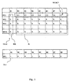
- Figure 1 shows a general schematics of the trace identifier TI as defined by the above standards.
- a 16-bytes trace identifier TI-16 consists of 16-bytes, BY1 to BY16, each one consisting of 8 bits, B1 to B8.
- Each first bit B1 of each byte BY1 ... BY16 represents theframe start marker MK.
- Bits B2 ... B8 of the first byte BY1 are C1 ... C7 bits forming a validation word WCRC7, and they are the result of the cyclic redundancy code operation over the previous transmitted trace identifier TI.
- the remaining bits, indicated as a whole with X form the data bits D i of the trace identifier TI, which belong to each input wherefrom the frame is coming.
- a 1-byte trace identifier TI-1 merely consists of 1-byte BY1, which is formed by 8 bits B1 to B8 representing a number ranging 0 to 255.
- EP 0 766 421 discloses a mismatch detection method in trace identifiers contained in SDH-coded data frames.
- D1 provides for two check steps, a validation step and a comparison step between the received trace identifier and an expected trace identifier.
- the two steps in D1 are not carried out in parallel and furthermore are executed only using 16 bytes trace identifiers and through the so called persistency check method.
- Persistency check with depth N means that a trace identifier which is periodically transmitted has to be observed at the receiving side for N consecutive times to be considered valid (i.e. not affected by transmission errors). This results in an apparatus requiring an high number (48) of memory cells for storing three 16-bytes strings and operating in a slow manner.
- the method and apparatus according to D1 is not usable for 1-byte string trace identifiers.
- the method and circuit according to the invention should use a reduced amount of memory to process trace identifiers, both 1-byte and 16-bytes trace identifiers.
- the mismatch detection method comprises the steps of: a) validating the received trace identifier and issuing a correspondent validation signal; b) comparing the received trace identifier with an expected trace identifier and issuing a correspondent match signal; c) evaluating the validation signal and the match signal; and d) generating a matching state signal according to the result of the evaluation as per step c), and is characterized in that the steps a) and b) are executed in parallel and further in that steps a) to d) are provided both for 16-bytes length trace identifiers and 1-byte length trace identifiers, wherein the validating step is carried out through a Cyclic Redundancy Code check in case of 16-bytes length trace identifiers and a Persistency Check in case of 1-byte length trace identifiers.
- the mismatch detection circuit according to the invention comprises:
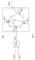
- Figure 2 shows a mismatch detection circuit 1 in trace identifiers.
- a sequence of trace identifiers Tl is indicated on the input to the mismatch detection circuit 1 in trace identifiers.
- said trace identifiers TI are contained in the header of a frame SDH, wherein they are assigned a determined position.
- Said mismatch detection circuit 1 can be included in any receiver within the communication network, not only at network outputs, but in all network nodes where the frame SDH is opened to verify the matching of the trace identifier TI.
- the sequence of trace identifiers TI inputs a 16-bytes validation block VAL16 and in parallel a 1-byte validation block VAL1. Moreover, said 16-bytes validation block VAL16 and 1-byte validation block VAL1 receive at one of their further inputs, an expected length signal S161. Said expected length signal S161 contains information as to whether the trace identifier TI has a 16-bytes length or 1-byte length. The expected length signal S161 can also be obtained at the receiver, measuring the length of the expected trace identifier TI.
- Both the 16-byte validation block VAL16 and the 1-byte validation block VAL1 have an output providing an equality signal SVAL1 or SVAL16, which can have three values: true value V, false value F, 'don't care value' DC. Additionally, the 16-bytes validation block VAL16 issues a correct validation word signal CRC7 to an output, whereas the 1-byte validation block VAL1 issues a constant packet signal CNST to an output.
- a combination block COMB Downstream the 16-bytes validation block VAL16 and the 1-byte validation block VAL1 a combination block COMB is provided, which is suitable to logically combine the equality signal SVAL1 and the equality signal SVAL16, in order to produce a single equality signal SVAL alone driving a finite states machine TMAC.
- Said finite states machine TMAC outputs a misconnection signal TIM161, which reaches an adder block SUM.
- a second finite states machine TMACX is located in parallel to the finite states machine TMAC.
- Said second finite states machine TMACX receives the correct validation word signal CRC7 and the constant packet signal CNST from the 16-byte validation block VAL16 and the 1-byte validation block VAL1, respectively. Consequently, a non structured identifier signal TIMX is originated by said second finite states machine TMACX and also sent to the adder block SUM, whose output produces the misconnection alarm signal TIM.
- Figure 3 shows the 16-bytes validation block VAL16. It comprises a multiframe aligner block ALL16, which generates a sync pulse SYNC every time two subsequent frame markers MK with 15 data bytes between are detected. The sync pulse SYNC is generated at the frame marker MK. Then a redundancy coding detector CRC and a mismatch detector DSL16 are provided. The redundancy coding detector CRC receives at one input the trace identifier Tl and at another input the sync pulse SYNC. The redundancy coding detector CRC outputs the correct word signal CRC7.
- Validation word WCRC7 is obtained inside the redundancy coding detector CRC by multiplying the polynomial representation of the trace identifier Tl by Z 7 , then by dividing module 2 by the generator polynomial Z 7 +Z 3 +1 and using the remainder after the division as the validation word WCRC7. This procedure for obtaining the validation word WCRC7 is known and coded by the standards previously mentioned.
- the resulting validation word WCRC7 is static, since also X bits are static.
- the validation word WCRC7 will not change provided there are no line errors. All trace identifiers Tl from one same source or transmitter contain the same validation word CRC7 and produce the same validation word CRC7 applying the redundancy code algorithm.
- the redundancy code detector CRC calculates the validation word CRC7 in a parallel and iterative mode.
- bits C i are the current value of the remainder polynomial Q
- bits NXC i are the next value of the next remainder polynomial Q
- bits D i correspond to bits X previously mentioned with reference to Fig. 1 of the incoming trace identifier TI
- NXCi correspond to the polynomial coefficients on the right in the expression (1).
- the validation word WCRC7 is computed as the trace identifier TI arrives, byte by byte, calculating bits NXCi iteratively till they represent the values of the validation word WCRC7.
- the sync pulse SYNC produced by the multiframe aligner block ALL16 initiates the redundancy coding detector CRC and the byte will reach the redundancy coding detector CRC after the bits Ci have been set to zero.
- a validation word WCRC7 calculated according to relations (2), which can be compared with bits C i contained in the next trace identifier TI. If the comparison gives a positive result, the redundancy code detector CRC will generate a correct validation word signal CRC7.
- the mismatch detector DSL16 compares the input received bytes of the trace identifier TI with the bytes of the expected trace identifier ETI, received at another input. This comparison operation is controlled at each sync pulse SYNC issued by the multiframe aligner block ALL16 and generates a matching signal MTC16, as a function of the matching or not of the 16 bytes of the received trace identifier TI with the 16 bytes of the expected trace identifier ETI.
- the matching signal MTC16 and correct validation word signal CRC7 are then sent to the input of a command generator CG16.
- Said command generator CG16 also receives the expected length signal S161 at its input and outputs the equality signal SVAL16, which takes the following values:
- the command generator CG16 will cause evolution of the finite states machine TMAC only if the received trace identifier TI is validated.
- FIG. 4 shows a diagram of the 1-byte validation block VAL1.
- Said 1-byte validation block VAL1 receives at its input the trace identifier TI, the expected length signal S161 and the expected trace identifier ETI.
- a module sexteen counter block CNT16 is provided. Said module sixteen counter block generates the sync pulse SYNC every 16-bytes. Therefore, the module sixteen counter block CNT16 performs a function quite similar to that of the multiframe aligner ALL16, i.e. it generates the sync pulse SYNC, but it will only emulate its behaviour.
- 1-bite length trace identifiers TI are apparently not structured in frames nor do they contain frame markers, so that the module sixteen counter block CNT16 will limit itself to issue the sync pulse SYNC with the same period of the multiframe aligner block ALL16, so as to maintain a temporary matching between the 16-bytes validation block VAL16 and the 1-byte validation block VAL1. Therefore, a 16-bytes integrator block IGT similar to the structure of the 16-bytes validation block VAL16 is provided, which will start integrating the received bytes upon receiving the sync pulse SYNC; if 16 subsequent bytes are equal, then the 16-bytes integrator block IGT will issue a constant packet signal CNST.
- a matching detector DSL1 receives at its inputs the trace identifier TI and the expected trace identifier ETI, compares it and generates a matching signal MTC1. This comparison is controlled by the sync pulse, so that the matching signal MTC1 will be issued if the 16 bytes received are matching with the expected trace identifier ETI.
- a command generator CG1 identical to the command generator CG16 is provided. Then, the matching signal MTC1 and constant packet signal CNST are sent to the input of a command generator CG1. Said command generator CG1 also receives on its input the expected length signal S161 and outputs an equality signal SVAL1, which takes the following values:
- Figure 5 shows the end part of the diagram of Figure 2, with the combiner block COMB, and with the finite states machine TMAC represented by its state diagram.
- the combiner block COMB is a logic circuit whose function consists substantially in summing up equality signals SVAL1 and SVAL16 to obtain a correct equality signal SVAL.
- SVAL equality signal
- the equality signal SVAL will take the value between the equality signal SVAL1 and the equality signal SVAL16 that does not correspond to the don't care value DC.
- both the equality signals SVAL1 and SVAL16 take the don't care value DC. Then, in this instance the equality signal SVAL will also take the don't care value DC.
- the finite states machine TMAC consists of four states:
- the second finite states machine TMACX is similar to the finite states machine TMAC, but it will generate a non structured packet signal TIMX if a correct validation signal CRC7 or a constant packet signal CNST is not received within 8 times 16- bytes.
- the misconnection alarm signal TIM results from the sum of the misconnection event signal TIM161 and non structured packet signal TIMX.
- the trace identifier Tl is sent to two parallel branches, of which one is related to 16-bytes length trace identifiers TI, i.e. the 16-bytes validation block VAL16, and the other is related to 1-byte length trace identifiers TI and 1-byte validation block VAL1.
- the 16-bytes block VAL16 and 1-byte validation block VAL1 have a functionally similar structure, even if some differences are due to the different frame length and structure they have to handle.
- Said blocks include in fact means for generating the sync pulse SYNC, i.e. the module sixteen counter block CNT16 and the multiframe aligner block ALL16, timing the operation of both the validation means of the received identifier and matching control means between the received identifier and expected identifier.
- Matching control means i.e. the matching detector DSL1 and matching detector DSL16
- validations means of the received identifier i.e. the redundancy coding detector CRC and 16-bytes integrator block IGT
- CRC7 and constant identifier signal CNST the correct validation word signal CRC7 and constant identifier signal CNST
- the trace identifier TI does not need to be stored in a memory circuit, but both the validation operation and comparison operation in the trace identifier TI will gradually occur simultaneously in parallel as the bytes of the trace identifier TI are received.
- the finite states machine TMAC evolves only when the trace identifier TI is correct and intermediate states INT are provided to avoid e.g. that a double line error may lead to validation of a trace identifier Tl, which should not be validated, and a simultaneous comparison may generate a false matching signal MTC1 or MTC16, so that the finite states machine TMAC will immediately generate the misconnection signal TIM, when the subsequent identifiers will then have generated 'don't care' or 'true' conditions.
- the mismatch detection method in trace identifiers contained in frames, in particular SDH-coded data frames in a telecommunication network allows validation and a comparison with the expected trace identifiers having different lengths and structures.
- the mismatch detection method and circuit in trace identifiers contained in SDH frames allows parallel execution of validation and comparison, analysing the trace identifiers as they are received, without the need to preset memory circuits to store one or more frames.
- the coding word CRC-7 which is dictated by the above mentioned standards within the frame of a 16-bytes trace identifier to validate said 16-bytes trace identifiers, is advantageously used. Moreover, a parallel calculation procedure to the validation word CRC-7 is implemented, which also avoids the use of memory circuits for frame storage and execution of the required polynomial operations. Said calculation procedure is particularly beneficial as it uses the validation word CRC-7 already provided in the trace identifier, not for the purposes of validation operations, but merely for error detection in the identifiers.
- the use of a finite states machine is advantageously provided to generate the misconnection signal, so that through the structure of said finite states machine misconnection signal events can be put in relation with line errors events.
- the mismatch detection method and circuit in trace identifiers in SDH frames allow detection and a consequent action for each bit sequence, which may come up at the receiver, in other words a 16-bytes trace identifier, a 1-byte trace identifier or a mismatch sequence with respect to the first two.
- a persistence type method may be equally used for the 16-byte string validation, such as used for the 1-byte trace identifier, i.e. an integration operation.
Landscapes
- Engineering & Computer Science (AREA)
- Computer Networks & Wireless Communication (AREA)
- Signal Processing (AREA)
- Maintenance And Management Of Digital Transmission (AREA)
- Detection And Prevention Of Errors In Transmission (AREA)
- Time-Division Multiplex Systems (AREA)
Description
- Figure 1 shows a trace identifiers schematics to be used jointly with the mismatch detection method in trace identifiers contained in frames, in particular SDH-coded data frames within a telecommunication network, according to the present invention;
- Figure 2 shows a schematics of a circuit implementing the mismatch detection method in trace identifiers contained in frames, in particular SDH-coded data frames within a telecommunication network, according to the present invention;
- Figure 3 shows a schematics of circuitry details of the circuit implementing the mismatch detection method in trace identifiers contained in frames, in particular SDH-coded data frames within a telecommunication network, in a communication network as represented in Figure 2;
- Figure 4 shows a schematics of second circuitry details of the circuit implementing the mismatch detection method in trace identifiers contained in frames, in particular SDH coded data frames within a communication network as represented in Figure 2; and
- Figure 5 shows a schematics of third circuitry details of the circuit implementing the mismatch detection method in trace identifiers contained in frames, in particular SDH-coded data frames within a telecommunication network as represented in Fig. 2.
| 1* Z134+O*Z133+..+0*Z127+ | 1-byte with |
| 0*Z126+X*Z125+...+X*Z119+ | 2nd byte |
| ...+ | |
| 0*Z14+X*Z13+...+X*Z7+ | |
| 0*Z6+0*Z5+...+0*Z0 | multiplication by Z7 |
- true value V, if the correct validation word signal CRC7 is true, the matching signal MTC16 is true and the expected length signal S161 indicates a 16-bytes length;
- false value F, if the correct validation word signal CRC7 is true and the matching signal MTC16 is false or the expected length signal S161 indicates a 1-byte length;
- do not care value DC in all the other cases.
- true value V, if the constant identifier signal CNST is true, the matching signal MTC1 is true and the expected length signal S161 indicates 1-byte length.
- false value F, if the constant identifier signal CNST is true and the matching signal MTC1 is false or the expected length signal S161 indicates a 16-bytes length.
- do not care value DC in all the other cases.
Claims (13)
- Mismatch detection method in trace identifiers contained in frames, in particular SDH-coded data frames, within a telecommunication network, wherein said received trace identifiers (TI) are compared with expected trace identifiers in determined locations of the telecommunication network, for verifying if a misconnection event has occurred and generating a corresponding alarm signal, said method comprising the following steps:a) validating (VAL16, VAL1) the received trace identifier (TI) and issuing a correspondent validation signal (CRC7, CNST);b) comparing (DSL16, DSL1) the received trace identifier (TI) with an expected trace identifier (ETI) and issuing a correspondent match signal (MTC1, MTC16);c) evaluating (CG16, CG1) the validation signal (CRC7, CNST) and the match signal (MTC1, MTC16); andd) generating a matching state signal (SVAL1, SVAL16) according to the result of the evaluation as per step c), and being characterized in that the steps a) and b) are executed in parallel and further in that steps a) to d) are provided both for 16-bytes length trace identifiers (TI) and 1-byte length trace identifiers (TI), wherein the validating step is carried out through a Cyclic Redundancy Code (CRC) check in case of 16-bytes length trace identifiers and a Persistency Check in case of 1-byte length trace identifiers.
- Method according to claim 1, characterized in that step d) includes the step of generating a matching state signal (SVAL1, SVAL16) taking a plurality of different logic states (V, F, DC), in particular three, one of which is represented by a true logic state (V) controlling the issue of an alarm signal (TIM).
- Method according to claim 2, characterized in that the step of generating a matching state signal (SVAL1, SVAL16) includes the step of generating a signal (SVAL1, SVAL16) further taking a false logic state (F) and a don't care logic state (DC) wherein the don't care state (DC) is associated with a missed validation signal (CRC7, CNST).
- Method according to claim 2, characterized in that the step of generating a matching state signal (SVAL1, SVAL16) taking the true logic state (V) is determined at least by the simultaneous receipt of both the validation signal (CRC7, CNST) and the matching signal (MTC1, MTC16).
- Method according to claim 3, characterized in that the step of generating a matching state signal (SVAL1, SVAL16) taking the false logic state (F) is determined at least by the simultaneous receipt of the validation signal (CRC7, CNST) and missed matching signal (MTC1, MTC16).
- Method according to claim 4, characterized in that it further includes the step of providing an expected length signal (S161) of the trace identifier (TI) and using it in step c) combined with the validation signal (CRC7, CNST) and the matching signal (MTC1, MTC16).
- Method according to any of claims 1-6, characterized in that step a) is executed using a validation word (WCRC7) contained in the 16-bytes length trace identifier (TI) and cyclic redundancy coding algorithm.
- Method according to claim 7, characterized in that the validation step a) is executed using the validation word (WCRC7) which is calculated upon receiving the trace identifier (TI) by an iterative procedure performing an iteration for each byte (BY1 ... BY16) received.
- Method according to claim 8, characterized in that said iterative procedure comprises the following steps: i) executing a division operation between the polynomial representation of each byte (BY1 ... BY16) of the received trace identifier and a polynomial generator; ii) executing a summing operation between the remainder of said division operation and the polynomial representation of the subsequent byte; iii) executing a division operation between the result of said summing operation and the polynomial generator; and iv) executing an iterative repetition of steps ii) to iii) for all bytes (BY1 ... BY16) of said trace identifier (TI):
- Method according to claim 6, characterized in that it further comprises the step of using the mismatch state signal (SVAL1, SVAL16) to drive the evolution of a finite states logic means (TMAC).
- Mismatch detection circuit in trace identifiers (TI) contained in data frames, particularly SDH-coded data frames, within a telecommunication network, the circuit comprising:means (VAL16, VAL1) for validating the received trace identifiers (TI) and issuing a correspondent validation signal (CRC7, CNST);means (DSL16, DSL1) for comparing the received trace identifier (TI) with an expected trace identifier (ETI) and issuing a correspondent match signal (MTC16, MTC1);means (CG16, CG1) for evaluating the validation signal (CRC7, CNST) and the match signal (MTC16, MTC1); andmeans, respondent to said evaluating means (CG16, CG1), for generating a matching state signal (SVAL1, SVAL16), characterized in that said validation means (VAL16, VAL1) and said match detection means are arranged in parallel with respect to the input of the received trace identifier (Tl) with both their outputs being connected with a logic means (CG1, CG16) suitable to generate match state signals (SVAL16, SVAL1) and in that the circuit is able to operate on both 16-bytes length trace identifiers (TI) and 1-byte length trace identifiers (TI), wherein the validating means operate through a Cyclic Redundancy Code (CRC) check in case of 16-bytes length trace identifiers and a Persistency Check in case of 1-byte length trace identifiers.
- Circuit according to claim 11, characterized in that it further includes a finite states logic means (TMAC), the match state signals (SVAL1, SVAL16) being sent to said finite states logic means (TMAC) in order to generate a misconnection alarm signal (TIM).
- Circuit according to claim 12, characterized in that it further includes an auxiliary finite states logic means (TMACX) which is arranged in parallel to the finite states logic means (TMAC) and is able to issue a non structured identifier signal (TIMX) after receipt of validation signals (CRC7, CNST).
Applications Claiming Priority (3)
| Application Number | Priority Date | Filing Date | Title |
|---|---|---|---|
| ITTO980323 | 1998-04-15 | ||
| IT98TO000323A ITTO980323A1 (en) | 1998-04-15 | 1998-04-15 | METHOD AND CIRCUIT FOR DETECTION OF INEQUALITIES IN TRACK IDENTIFICATION PACKAGES IN SDH PLOTS. |
| PCT/EP1999/002414 WO1999053641A1 (en) | 1998-04-15 | 1999-03-26 | Mismatch detection in sdh frame trace identifiers |
Publications (2)
| Publication Number | Publication Date |
|---|---|
| EP1072114A1 EP1072114A1 (en) | 2001-01-31 |
| EP1072114B1 true EP1072114B1 (en) | 2002-05-22 |
Family
ID=11416683
Family Applications (1)
| Application Number | Title | Priority Date | Filing Date |
|---|---|---|---|
| EP99923409A Expired - Lifetime EP1072114B1 (en) | 1998-04-15 | 1999-03-26 | Mismatch detection method and circuit in trace identifiers in a sdh frame |
Country Status (6)
| Country | Link |
|---|---|
| US (1) | US6647519B1 (en) |
| EP (1) | EP1072114B1 (en) |
| CA (1) | CA2328063A1 (en) |
| DE (1) | DE69901553T2 (en) |
| IT (1) | ITTO980323A1 (en) |
| WO (1) | WO1999053641A1 (en) |
Families Citing this family (2)
| Publication number | Priority date | Publication date | Assignee | Title |
|---|---|---|---|---|
| US6985845B1 (en) * | 2000-09-26 | 2006-01-10 | Koninklijke Philips Electronics N.V. | Security monitor of system runs software simulator in parallel |
| US7603588B1 (en) * | 2004-04-20 | 2009-10-13 | Cisco Technology, Inc. | Two-stage detection of trace identifier mismatches |
Family Cites Families (10)
| Publication number | Priority date | Publication date | Assignee | Title |
|---|---|---|---|---|
| DE2759106C2 (en) * | 1977-12-30 | 1979-04-05 | Siemens Ag, 1000 Berlin Und 8000 Muenchen | Circuit arrangement for coding or decoding binary information |
| JPH0870290A (en) | 1994-08-29 | 1996-03-12 | Fujitsu Ltd | Fault monitoring equipment for transmission equipment |
| JP2671834B2 (en) | 1994-11-11 | 1997-11-05 | 日本電気株式会社 | Error detection circuit |
| JP2616486B2 (en) * | 1995-05-17 | 1997-06-04 | 日本電気株式会社 | Synchronous network ring network system |
| DE19536475C2 (en) | 1995-09-29 | 1998-05-28 | Siemens Ag | Method for recognizing a path trace and a section trace in SDH signal sequences |
| JP3775859B2 (en) * | 1996-07-05 | 2006-05-17 | 富士通株式会社 | Path switch ring controller in synchronous (SDH) network including asynchronous (PDH) subnetwork |
| US6421322B1 (en) * | 1997-11-17 | 2002-07-16 | Adc Telecommunications, Inc. | System and method for electronically identifying connections of a cross-connect system |
| US6104702A (en) * | 1998-03-06 | 2000-08-15 | Lucent Technologies Inc. | Apparatus and method for extending operation of non-intrusive monitors in SDH |
| JP3439649B2 (en) * | 1998-03-16 | 2003-08-25 | 富士通株式会社 | Path trace check method and apparatus |
| US6426958B1 (en) * | 1998-03-31 | 2002-07-30 | Alcatel Usa Sourcing, L.P. | System and method for performance monitoring telecommunication signals having various formats |
-
1998
- 1998-04-15 IT IT98TO000323A patent/ITTO980323A1/en unknown
-
1999
- 1999-03-26 EP EP99923409A patent/EP1072114B1/en not_active Expired - Lifetime
- 1999-03-26 CA CA002328063A patent/CA2328063A1/en not_active Abandoned
- 1999-03-26 US US09/673,184 patent/US6647519B1/en not_active Expired - Fee Related
- 1999-03-26 DE DE69901553T patent/DE69901553T2/en not_active Expired - Fee Related
- 1999-03-26 WO PCT/EP1999/002414 patent/WO1999053641A1/en not_active Ceased
Also Published As
| Publication number | Publication date |
|---|---|
| WO1999053641A1 (en) | 1999-10-21 |
| EP1072114A1 (en) | 2001-01-31 |
| ITTO980323A0 (en) | 1998-04-15 |
| DE69901553T2 (en) | 2003-01-09 |
| ITTO980323A1 (en) | 1999-10-15 |
| DE69901553D1 (en) | 2002-06-27 |
| CA2328063A1 (en) | 1999-10-21 |
| US6647519B1 (en) | 2003-11-11 |
Similar Documents
| Publication | Publication Date | Title |
|---|---|---|
| US5131012A (en) | Synchronization for cylic redundancy check based, broadband communications network | |
| US6014767A (en) | Method and apparatus for a simple calculation of CRC-10 | |
| US5844923A (en) | Fast framing of nude ATM by header error check | |
| US7277459B1 (en) | Data transmission in an SDH network | |
| US6983414B1 (en) | Error insertion circuit for SONET forward error correction | |
| JPH09284245A (en) | Error correction coding decoding method for stm-n signal, error correction coding circuit for stm-n signal and error correction decoding circuit for stm-n signal | |
| US7003715B1 (en) | Galois field multiply accumulator | |
| JPH10190606A (en) | Path test signal generating circuit and path test signal inspecting circuit of digital transmission system and synchronous transmission device | |
| KR100234213B1 (en) | A method and apparatus for a two-step calculation of crc-32 | |
| US6728925B2 (en) | Error correcting method and apparatus | |
| JPH05304519A (en) | Frame synchronization circuit | |
| US7124064B1 (en) | Automatic generation of hardware description language code for complex polynomial functions | |
| US6647519B1 (en) | Mismatch detection in SDH frame trace identifiers | |
| CA2325090C (en) | Performance monitoring for optical transmission system | |
| US6920149B2 (en) | Digital data transmission system | |
| CA2086146C (en) | Logical machine for processing control information of telecommunication transmission frames | |
| US7447982B1 (en) | BCH forward error correction decoder | |
| US6973599B2 (en) | Method of and system for constructing valid data for memory-based tests | |
| KR100189267B1 (en) | Device for establishing cell boundaries in a bit stream and crc calculation | |
| JP3173713B2 (en) | Error correction encoding method and transmission / reception device | |
| EP0840462B1 (en) | A method and apparatus for a two-step calculation of CRC-32 | |
| KR100396620B1 (en) | Apparatus and Method for generating STM1 frame in SDH apparatus | |
| JP2564034B2 (en) | Functional test method and test circuit in frame format of digital transmission system | |
| Cheung et al. | Combined framing and error correction coding for the ds3 signal format | |
| KR100539668B1 (en) | ATM CELL boundary discriminating equipment of DS3 UNI of SDH |
Legal Events
| Date | Code | Title | Description |
|---|---|---|---|
| PUAI | Public reference made under article 153(3) epc to a published international application that has entered the european phase |
Free format text: ORIGINAL CODE: 0009012 |
|
| 17P | Request for examination filed |
Effective date: 20000926 |
|
| AK | Designated contracting states |
Kind code of ref document: A1 Designated state(s): DE ES FI FR GB IT SE |
|
| GRAG | Despatch of communication of intention to grant |
Free format text: ORIGINAL CODE: EPIDOS AGRA |
|
| RIC1 | Information provided on ipc code assigned before grant |
Free format text: 7H 04J 3/14 A |
|
| RTI1 | Title (correction) |
Free format text: MISMATCH DETECTION METHOD AND CIRCUIT IN TRACE IDENTIFIERS IN A SDH FRAME |
|
| RIC1 | Information provided on ipc code assigned before grant |
Free format text: 7H 04J 3/14 A |
|
| RTI1 | Title (correction) |
Free format text: MISMATCH DETECTION METHOD AND CIRCUIT IN TRACE IDENTIFIERS IN A SDH FRAME |
|
| 17Q | First examination report despatched |
Effective date: 20010801 |
|
| GRAG | Despatch of communication of intention to grant |
Free format text: ORIGINAL CODE: EPIDOS AGRA |
|
| GRAH | Despatch of communication of intention to grant a patent |
Free format text: ORIGINAL CODE: EPIDOS IGRA |
|
| GRAH | Despatch of communication of intention to grant a patent |
Free format text: ORIGINAL CODE: EPIDOS IGRA |
|
| GRAA | (expected) grant |
Free format text: ORIGINAL CODE: 0009210 |
|
| PG25 | Lapsed in a contracting state [announced via postgrant information from national office to epo] |
Ref country code: FI Free format text: LAPSE BECAUSE OF FAILURE TO SUBMIT A TRANSLATION OF THE DESCRIPTION OR TO PAY THE FEE WITHIN THE PRESCRIBED TIME-LIMIT Effective date: 20020522 |
|
| REG | Reference to a national code |
Ref country code: GB Ref legal event code: FG4D |
|
| REF | Corresponds to: |
Ref document number: 69901553 Country of ref document: DE Date of ref document: 20020627 |
|
| PG25 | Lapsed in a contracting state [announced via postgrant information from national office to epo] |
Ref country code: SE Free format text: LAPSE BECAUSE OF FAILURE TO SUBMIT A TRANSLATION OF THE DESCRIPTION OR TO PAY THE FEE WITHIN THE PRESCRIBED TIME-LIMIT Effective date: 20020822 |
|
| ET | Fr: translation filed | ||
| PG25 | Lapsed in a contracting state [announced via postgrant information from national office to epo] |
Ref country code: ES Free format text: LAPSE BECAUSE OF FAILURE TO SUBMIT A TRANSLATION OF THE DESCRIPTION OR TO PAY THE FEE WITHIN THE PRESCRIBED TIME-LIMIT Effective date: 20021128 |
|
| PLBE | No opposition filed within time limit |
Free format text: ORIGINAL CODE: 0009261 |
|
| STAA | Information on the status of an ep patent application or granted ep patent |
Free format text: STATUS: NO OPPOSITION FILED WITHIN TIME LIMIT |
|
| 26N | No opposition filed |
Effective date: 20030225 |
|
| PGFP | Annual fee paid to national office [announced via postgrant information from national office to epo] |
Ref country code: GB Payment date: 20080320 Year of fee payment: 10 |
|
| PGFP | Annual fee paid to national office [announced via postgrant information from national office to epo] |
Ref country code: DE Payment date: 20080321 Year of fee payment: 10 |
|
| PGFP | Annual fee paid to national office [announced via postgrant information from national office to epo] |
Ref country code: IT Payment date: 20080327 Year of fee payment: 10 |
|
| PGFP | Annual fee paid to national office [announced via postgrant information from national office to epo] |
Ref country code: FR Payment date: 20090312 Year of fee payment: 11 |
|
| GBPC | Gb: european patent ceased through non-payment of renewal fee |
Effective date: 20090326 |
|
| PG25 | Lapsed in a contracting state [announced via postgrant information from national office to epo] |
Ref country code: DE Free format text: LAPSE BECAUSE OF NON-PAYMENT OF DUE FEES Effective date: 20091001 |
|
| PG25 | Lapsed in a contracting state [announced via postgrant information from national office to epo] |
Ref country code: GB Free format text: LAPSE BECAUSE OF NON-PAYMENT OF DUE FEES Effective date: 20090326 |
|
| REG | Reference to a national code |
Ref country code: FR Ref legal event code: ST Effective date: 20101130 |
|
| PG25 | Lapsed in a contracting state [announced via postgrant information from national office to epo] |
Ref country code: FR Free format text: LAPSE BECAUSE OF NON-PAYMENT OF DUE FEES Effective date: 20100331 |
|
| PG25 | Lapsed in a contracting state [announced via postgrant information from national office to epo] |
Ref country code: IT Free format text: LAPSE BECAUSE OF NON-PAYMENT OF DUE FEES Effective date: 20090326 |