EP1071864B1 - A system and method for locating a tool in a wellbore, a tubular and a device for the system - Google Patents
A system and method for locating a tool in a wellbore, a tubular and a device for the system Download PDFInfo
- Publication number
- EP1071864B1 EP1071864B1 EP99911937A EP99911937A EP1071864B1 EP 1071864 B1 EP1071864 B1 EP 1071864B1 EP 99911937 A EP99911937 A EP 99911937A EP 99911937 A EP99911937 A EP 99911937A EP 1071864 B1 EP1071864 B1 EP 1071864B1
- Authority
- EP
- European Patent Office
- Prior art keywords
- key
- tubular
- profile
- slot
- sleeve
- Prior art date
- Legal status (The legal status is an assumption and is not a legal conclusion. Google has not performed a legal analysis and makes no representation as to the accuracy of the status listed.)
- Expired - Lifetime
Links
- 238000000034 method Methods 0.000 title claims description 8
- 230000008878 coupling Effects 0.000 claims description 31
- 238000010168 coupling process Methods 0.000 claims description 31
- 238000005859 coupling reaction Methods 0.000 claims description 31
- 230000003213 activating effect Effects 0.000 claims description 12
- 230000000717 retained effect Effects 0.000 claims description 2
- 238000005452 bending Methods 0.000 description 2
- 238000010276 construction Methods 0.000 description 2
- 239000000463 material Substances 0.000 description 2
- 238000003801 milling Methods 0.000 description 2
- 238000010008 shearing Methods 0.000 description 2
- 229910000851 Alloy steel Inorganic materials 0.000 description 1
- OKTJSMMVPCPJKN-UHFFFAOYSA-N Carbon Chemical compound [C] OKTJSMMVPCPJKN-UHFFFAOYSA-N 0.000 description 1
- 241001331845 Equus asinus x caballus Species 0.000 description 1
- 235000008331 Pinus X rigitaeda Nutrition 0.000 description 1
- 235000011613 Pinus brutia Nutrition 0.000 description 1
- 241000018646 Pinus brutia Species 0.000 description 1
- 229910001297 Zn alloy Inorganic materials 0.000 description 1
- 229910052799 carbon Inorganic materials 0.000 description 1
- 238000005553 drilling Methods 0.000 description 1
- 239000000835 fiber Substances 0.000 description 1
- 238000005552 hardfacing Methods 0.000 description 1
- 230000002401 inhibitory effect Effects 0.000 description 1
- 239000011295 pitch Substances 0.000 description 1
- 230000002028 premature Effects 0.000 description 1
Images



Classifications
-
- E—FIXED CONSTRUCTIONS
- E21—EARTH OR ROCK DRILLING; MINING
- E21B—EARTH OR ROCK DRILLING; OBTAINING OIL, GAS, WATER, SOLUBLE OR MELTABLE MATERIALS OR A SLURRY OF MINERALS FROM WELLS
- E21B23/00—Apparatus for displacing, setting, locking, releasing or removing tools, packers or the like in boreholes or wells
- E21B23/004—Indexing systems for guiding relative movement between telescoping parts of downhole tools
- E21B23/006—"J-slot" systems, i.e. lug and slot indexing mechanisms
-
- E—FIXED CONSTRUCTIONS
- E21—EARTH OR ROCK DRILLING; MINING
- E21B—EARTH OR ROCK DRILLING; OBTAINING OIL, GAS, WATER, SOLUBLE OR MELTABLE MATERIALS OR A SLURRY OF MINERALS FROM WELLS
- E21B23/00—Apparatus for displacing, setting, locking, releasing or removing tools, packers or the like in boreholes or wells
-
- E—FIXED CONSTRUCTIONS
- E21—EARTH OR ROCK DRILLING; MINING
- E21B—EARTH OR ROCK DRILLING; OBTAINING OIL, GAS, WATER, SOLUBLE OR MELTABLE MATERIALS OR A SLURRY OF MINERALS FROM WELLS
- E21B23/00—Apparatus for displacing, setting, locking, releasing or removing tools, packers or the like in boreholes or wells
- E21B23/01—Apparatus for displacing, setting, locking, releasing or removing tools, packers or the like in boreholes or wells for anchoring the tools or the like
-
- E—FIXED CONSTRUCTIONS
- E21—EARTH OR ROCK DRILLING; MINING
- E21B—EARTH OR ROCK DRILLING; OBTAINING OIL, GAS, WATER, SOLUBLE OR MELTABLE MATERIALS OR A SLURRY OF MINERALS FROM WELLS
- E21B7/00—Special methods or apparatus for drilling
- E21B7/04—Directional drilling
- E21B7/06—Deflecting the direction of boreholes
- E21B7/061—Deflecting the direction of boreholes the tool shaft advancing relative to a guide, e.g. a curved tube or a whipstock
Definitions
- the present invention relates to a system and method for locating a tool in a wellbore, a tubular and a device of the system, and particularly but not exclusively, to a system for locating a whipstock in a string of casing.
- a particular example is in the positioning of a whipstock in a string of casing in the construction of multilateral or horizontal wells.
- whipstocks Prior to the present invention, whipstocks were lowered on a tool string or wireline.
- the whipstock was anchored in place using pads activated by a trip bar. Correct positioning and orientation is difficult to achieve. It is important that an anchor be activated only at a desired location in the string of casing and that an anchor not be activated prematurely. Closest prior art is either of US-A-5531271, US-A-5595247 corresponding to the preamble of claim 1.
- said tubular has an inner diameter and the profile is positioned beyond said inner diameter so that the profile does not project into said tubular.
- This can be achieved by milling a profile from the inside wall of a section of tubular or casing.
- a coupling may be manufactured to a high tolerance and used in a string of tubulars or casing, thereby inhibiting structural weaknesses in the string.
- the coupling could be made from an alternative material such as carbon fibre, high grade steel alloys or a zinc alloy.
- Tubular members or couplings may have slots or profiles that are configured, sized, and disposed so that the slots or profiles do not block or intrude therein.
- the profile may be a projection such as a lug.
- said profile comprises a slot for receiving a key of said device.
- the profile my comprise a muleshoe slot with upper tapered portions on either side of a lower slot portion, the upper tapered portions for guiding the lug down into the lower slot portion.
- the key is movable into the slot thus indicating that an item, e.g. but not limited to a whipstock, is oriented in a particular known position when the location of the slot with respect to the earth's surface and when the orientation of the slot radially with respect to the wellbore is known.
- said key is biased outwardly from said device.
- said key is initially retained by a sleeve.
- said sleeve comprises friction engaging means which engage said tubular, such that upon a predetermined movement of said device relative to said tubular, said key is released.
- the friction engaging means engage said tubular isolating the profile from weight of the system.
- said sleeve comprises a slot, such that, in use said key is released therethrough upon alignment therewith.
- one of said device and said sleeve comprises a pin and the other of said device and said sleeve comprises an indexing channel, such that upon said predetermined movement of said device relative to said tubular, said pin follows said indexing channel to align said slot with said key.
- the system further comprising a second key.
- said second key is biased outwardly from said device.
- said device comprises a body with a rotatable member arranged therein, said key arranged on said rotatable member and projects through a window in body.
- said rotatable member is shear pinned to said body.
- said device comprises a second rotatable member arranged in said body, said second key arranged on said second rotatable member and projects through a window in said body.
- said second rotatable member is shear pinned to said body.
- a second slot is provided in said sleeve such that when said second key is aligned therewith said second key projects therethrough.
- the first and second keys follow the profile.
- said first slot is radially offset from and positioned below said second slot.
- the key offset feature and thus the sequential key movement into the slot, provides a fail-safe feature that prevents actuation of a setting mechanism until correct orientation has been achieved.
- said first slot is wider than said second slot so that said first key is movable to contact said profile and move downwardly therein prior to the second key contacting said profile.
- said second member is disposed above said first member.
- alignment of said second key with said profile activates an activating member.
- the first key locates in the profile to obtain a known orientation.
- the second key locates in the profile which releases or activates a setting mechanism to lock a tool to the string of tubulars.
- said activating member activates a setting mechanism.
- said activating member is releasably secured to said setting mechanism by a shear member, following release said activating member is movable to contact said second member so that force of the said activating member against the second member shears the shear member.
- the keys and their respective members are disposed so that the activating member is movable to contact said second tubular member only after the second key contacts said profile.
- the system further comprising a concave.
- system further comprises a mill releasably connected to said concave.
- the system further comprises a tubular string to which the mill is connected.
- the system further comprises a flexible member connected between said device and said tool.
- the flexible member, flexible pipe, flexible joint or flexible coupling is used in the system to accommodate bending or flexing thereof; in one aspect, such a flexible item is disposed between the setting mechanism and the wellbore locator system.
- the tubular supports the weight of the system.
- the present invention also provides a method for locating a tool in a wellbore using the system, the method comprising the step of lowering said device in a wellbore and engaging said profile, whereupon a tool is located.
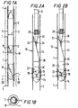
- a wellbore tubular string S disposed in an earth wellbore W has a plurality of couplings C interconnecting tubulars T of the string S.
- Each coupling C has a mule shoe profile M and slot L which, as shown in Fig. 1B do not project further inwardly than the inner diameter D of the tubulars T.
- Each coupling C is at a known location in the wellbore W. This location may be determined using known devices and methods.
- the couplings, and therefore their respective slots, may be disposed with any orientation. The orientation of a slot in a particular coupling may be determined with known techniques and devices.
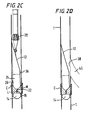
- Figs. 2A to 2F show schematically a system 10 according to the present invention approaching with a whipstock 12, friction device 14, first tubular member 16 with first lower key 18, second tubular member 20 with second upper key 22, and setting mechanism 24 with slips 26.
- a mill system 28 is used attached to a tubular string R (shown in Fig. 2A) with at least one mill, including but not limited to, a starting mill 30 releasably secured to a lug 32 of the whipstock 12 with a shear stud 34.
- Fig. 2A shows the system 10 approaching one of the couplings C.
- the friction device 14 has engaged an inner wall of a tubular T so that an inner portion of the system that includes the tubular members 16 and 20 can be lifted with respect to an outer sleeve (not shown; described with respect to the embodiment of Fig. 3A, below).
- the outer sleeve is attached to the friction device 14.
- neither key has yet contacted the muleshoe profile M of the coupling C.
- the coupling C does not support the weight of the system 10 and the system is not fixed to the coupling C.
- the tubular T is part of a string disposed in a wellbore like the wellbore W (Fig. 1A).
- the inner portion of the system 10 has been lifted and rotated so that the first lower key 18 is released to project through a window in the outer sleeve (as described below) to engage the muleshoe profile M and move down in the slot L, thus assuring correct orientation of the whipstock 12.
- the second upper key 22 has projected through a corresponding sleeve window (not shown) and moved down in the slot L.
- the alignment of the upper and lower keys followed by additional downward movement of the keys in the slot permits setting of the slips 26.
- the lower key 18, its rotatable member 16 along with the upper key 22 and its rotatable member 20 do not move down further once in the bottom of the slot L.
- Inner parts of the system move down so that the trip bar contacts the upper key's tubular member 20 shearing a roll pin (as described below) and effecting setting of the slips 26. Tripping of the setting mechanism 24 also moves the whipstock 12 on a fulcrum slip 36.
- the second upper key 22 is positioned as is the second tubular member 20 so that such setting cannot occur until the second upper key has moved down to the muleshoe profile.
- premature whipstock setting is prevented and whipstock setting occurs only following correct orientation of the whipstock by the action of the first lower key 18.
- overtravel is provided for with an extension of an upper window in a tool body through which the upper key projects and an extension of a control slot in an outer sleeve - all as described below in detail, e.g. with respect to Figs. 3A - 3F; i.e. the windows and slot extension prevent system lock-up.
- any known suitable whipstock with any known suitable whipstock setting device, mechanism, or apparatus and/or packer or anchor packer.
- Fig. 2D shows a window 38 milled through the tubular T (e.g. but not limited to casing) using any known mill or milling system diverted by the whipstock 12 and a lateral or sidetracked bore 40 created with any known device or system useful for making such a bore.
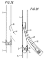
- Fig. 2E shows the completed bore 40 and the whipstock 12 removed from the tubulars T. It may be removed by any suitable known removal device or system and/or it may be milled out. Passage and/or flow through the tubulars T is now possible again.
- Fig. 2F shows a diverter whipstock 50 installed in the tubulars T of Fig. 2E.
- the diverter whipstock 50 provides a diverter device for subsequent operations in the bore 40, including, but not limited to, e.g. further drilling with a drill system 52 to extend and/or redirect the bore 40.
- the diverter whipstock may employ a single key (not shown) to achieve correct orientation and setting; or, alternatively, it may have a set of keys 54, 56 (like the keys 18, 22 described above) and related apparatus, as described above, for whipstock orientation and setting.
- the whipstock 12 may be left in place for further operations.
- Fig. 4A and 4B show a coupling 60 (one possible embodiment of a coupling C as in Fig. 1A) with an upper end 61 having inner tapered surfaces 62 and 63, a lower end 67 with an inner tapered surface 68 for facilitating movement of the keys 18 and 22 and other wellbore apparatuses therethrough.
- An inner muleshoe profile 64 with a slot 65 is formed in a wall 66 of the coupling 60.
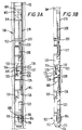
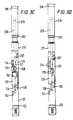
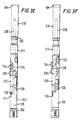
- Figs. 3A - 3F show a sequence of steps in the operation of a system 100 according to the present invention which can be used as the system 10 in Figs. 2A - 2D.
- the system 100 has a friction mechanism 102 with a plurality (one or more, four in the system 100) of spring-loaded blocks 104 constantly urged outwardly by springs 106 from recesses 108 in a body 110.
- the outer surfaces of the blocks 104 may be wholly coated with hardfacing material or intermittently striped therewith.
- a lower end 112 of the body 110 has a tapered nose 114 for ease of movement through tubulars of a tubular string.
- a collar 113 threadedly mated with the nose 114 holds the blocks 104 in place.
- An outer sleeve 120 is movably disposed around and encircles a first tubular member 124, a second tubular member 122 and a third tubular member 123.
- the two tubular members 122 and 124 are not interconnected and the upper one rests on the lower one.
- the third tubular member 123 is welded to a tool body 125.
- a lug 126 projects outwardly from the third tubular member 123 into a slot 130 through the outer sleeve 120.
- a first key 128 is initially held by the inner surface (shown cutaway in Fig. 3A) of the outer sleeve 120 in a recess 132 in the first tubular member 124 and in a window 135 in the tool body 125.
- a second key 134 is initially held in a recess 136 in the second tubular member 122 by the inner surface of the outer sleeve 120.
- the keys are extendable through a window 137 in the tool body 125.
- a screw or bolt 151 extending through the tubular member (122 or 124) projects into a recess 153 in the key and prevents the key from exiting completely from its tubular member.
- a trip bar 200 disposed above a top of the second tubular 122 is interconnected with a whipstock setting mechanism and a whipstock (shown schematically as SM and WS respectively in Fig. 3A).
- the whipstock WS is releasably attached to a mill M which is connected to a tubular string TS (both shown schematically in Fig. 3A) .
- the string TS extends to the earth surface from a wellbore WL in which the system 100 is to be set.
- Such a trip bar, setting mechanism, and whipstock are well known in the art (e.g., but not limited to, Weatherford's commercially available "WHIPBACK" whipstock).
- the tubular members 122, 123, and 124 are enclosed in the tool body 125.
- the tubular member 124 is sandwiched between the tubular members 122 and 123 within the tool body 125, but in one aspect, is connected to neither.
- the third tubular member 123 rests on the body 110 so that lifting the tool body 125 lifts the three tubular members.
- the trip bar 200 extends through an orientation adapter 202 and is releasably shear pinned thereto with a roll pin 203 that extends through the adapter 202 and into the trip bar 200.
- the trip bar 200 is movable downwardly once the roll pin is sheared by moving the string is downwardly to contact the top of the second tubular member 122.
- a device inserted into the well bore is generally identified by reference numeral 99 (Fig. 3G)
- Fig. 3C the inner parts that were lifted as shown in Fig. 3B are turned to the right by turning the tubular string TS.
- the outer sleeve 120 remains immobile and the keys 128 and 134 move to a position above their respective windows 160 and 135 respectively in the outer sleeve 120.
- the lug 126 has moved from the position of Fig. 3B to that of Fig. 3C (i.e. to the left in the figure).
- the tubular string TS has been moved down, which moves the keys 128 and 134 down so that they are urged outwardly by their respective springs through the windows 160 and 135, respectively.
- the downward movement of the tubular string is governed by the downward movement of the lug 126 in the slot 130 from the position shown in Fig. 3C to that of Fig. 3D.
- the two keys are urged simultaneously through their respective windows and that the windows are offset so that sequential engagement of the muleshoe slot of the coupling 209 is effected; i.e., in this embodiment, both keys can only project simultaneously.
- other window dispositions are envisaged so that sequential outward projection of the keys is possible.
- the keys 128 and 134 lock the outer sleeve 120 (and therefore the friction mechanism 102) to the rest of the system 100 so that movement of the tubular string with sufficient force moves the entire system 100.
- the entire system is moved down so that the key 128 contacts and moves down in the muleshoe slot 130 of the coupling 209.
- This force breaks the pin 207 (i.e. when the lower key 128 is down in the slot 130 and the upper key 134 has contacted the upper lip of the muleshoe slot).
- this force also shears the roll pin 203.
- the roll pin 203 is set to shear at a force (e.g. but not limited to 4500 pounds (4448.22 N), 1000 pounds (17792.88 N), or greater) that is greater than that at which the pin 207 shears (e.g. but not limited to at about 4400 pounds).
- the keys 128 and 134 are radially (one-above-the other) aligned and the lug 126 has moved to the position shown in the slot 130. Due to an extended upper part 213 of the window 135 in the tool body 125 and a lower portion 141 of the slot 130, downward movement of the tubular string and the parts connected thereto results in shearing of the roll pin 203 (if not already sheared) so that the trip bar 200 moves down (as shown in Fig. 3F) to abut a top 143 of the upper tubular member 122, beginning the setting sequence for setting of slips (not shown) which are part of the setting mechanism SM.
- the keys 128, 134 are locked into the outer sleeve 120 and are also bottomed out in the slot of the coupling 209 (i.e. the keys and outer sleeve are now held immobile). Also the friction mechanism 102 which is threadedly secured to the outer sleeve 120 is mobile.
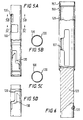
- Figs. 7A - 7C show the orientation adapter 202.
- the adapter 202 has a spline portion 233 that is movable within a portion 219 of the spline nut 211 (see Fig. 8A) when the spline portion 233 is disposed adjacent the portion 219.
- Threads 204 on the adapter 202 mate with threads 213 of the spline nut 211 and threads 212 of the spline nut 211 mate with exterior threads 159 of the tool body 125.
- the spline portion 233 of the adapter 202 engages an inner spline portion 157 of the tool body 125.
- Different pitches on the threads 212 and 213 provide for desired manipulation of the adapter 202 and spline nut 211.
- the spline portion 203 has a height about half that of the portion 219.
- Figs. 8A and 8B show the spline nut 211 that connects the orientation adapter 202 and the tool body 125.
- a bore 214 extends through the spline nut from top to bottom.
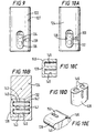
- Fig. 9 shows the upper tubular member 122 with its key 134.
- a hole 139 is provided for a bolt (not shown, like the bolt 151, Fig. 10A); and a hole 127 is provided for receiving part of the shear pin 207.
- Figs. 10A - 10B show the tubular member 124 with its key 128 and a bolt 151 holding the key 128 movably in its recess 132.
- springs 143 in key recesses 145 and body recesses 143 urge the key 128 outwardly.
- the 134 (Fig. 9) has similar structure and springs.
- a bevelled edge 149 facilitates upward movement of the system when the key is projecting from the tool body.
- a key may have a bevelled edge 149 and a tapered end 155 to facilitate key action and movement.
- non-bevelled keys without an end 155; keys with both ends bevelled as at 149 or with both ends like the end 155; and/or a key with either end bevelled as at 149 or with either end like the end 155.
- Figs. 11A - 11C show the outer sleeve 120 and its relation to the key 134 - which is similar to the relation to the key 128. Initially the outer sleeve 120 prevents the keys from projecting outwardly past the outer sleeve 120 (Fig. 11B). With proper system movement, the key 134 is aligned with the window 135 and moves through it (Fig. 11C).
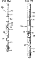
- Figs. 12A and 12B shown alternative embodiments of the system 100.
- the orientation adapter 202 is deleted and the trip bar 200 extends through a flexible item, e.g. a flexible coupling 240.
- the flexible coupling 240 is a Powertork (TM) Series F or S gear coupling as is commercially available from Systems Components, Inc. of South Haven, Michigan; however, any suitable flexible item or member may be used in place of the coupling 240 to accommodate bending and/or flexing of the system, including but not limited to a bendable piece of pine, drill pipe, or drill collar.
- TM Powertork
- S gear coupling any suitable flexible item or member may be used in place of the coupling 240 to accommodate bending and/or flexing of the system, including but not limited to a bendable piece of pine, drill pipe, or drill collar.
- Fig. 12B shows a system 1 which is like the system 100, but with the addition of a flexible coupling 240 (or flexible item or member as discussed above).
Landscapes
- Geology (AREA)
- Life Sciences & Earth Sciences (AREA)
- Engineering & Computer Science (AREA)
- Mining & Mineral Resources (AREA)
- Environmental & Geological Engineering (AREA)
- Fluid Mechanics (AREA)
- Physics & Mathematics (AREA)
- General Life Sciences & Earth Sciences (AREA)
- Geochemistry & Mineralogy (AREA)
- Earth Drilling (AREA)
- Excavating Of Shafts Or Tunnels (AREA)
- Drilling And Boring (AREA)
- Perforating, Stamping-Out Or Severing By Means Other Than Cutting (AREA)
Description
Claims (29)
- A system for locating a tool in a wellbore, said system comprising a profile (M) disposed in a tubular (T, C) and a device (99) for engaging said profile (M), wherein said device (99) is adapted to locate or engage said profile (M) and to be held in relation therewith, said device (99) being connectable or integral with a tool (12, 24), characterised in that the profile is arranged in the internal wall of the tubular and in that the tubular is a casing or coupling tubular forming part of a string of tubulars.
- A system as claimed in Claim 1, wherein said tubular (T, C) has an inner diameter and the profile (M) is positioned beyond said inner diameter so that the profile does not project into said tubular (T, C).
- A system as claimed in Claim 1 or 2, wherein said profile (M) comprises a slot (L) for receiving a key (18) of said device (99).
- A system as claimed in Claim 3, wherein said key (18) is biased outwardly from said device (99).
- A system as claimed in Claim 4, wherein said key (18) is initially retained by a sleeve (120).
- A system as claimed in Claim 5, wherein said sleeve (120) comprises friction engaging means (104) which engage said tubular (T, C), such that upon a predetermined movement of said device (99) relative to said tubular (T, C), said key (18) is released.
- A system as claimed in Claim 6, wherein the friction engaging means (104) engage said tubular isolating the profile (M) from weight of the system.
- A system as claimed in Claim 5, 6 or 7, wherein said sleeve (120) comprises a window (135), such that, in use said key (18) is released therethrough upon alignment therewith.
- A system as claimed in Claim 5, 6 or 7, wherein one of said device (99) and said sleeve (120) comprises a pin (126) and the other of said device (99) and said sleeve (120) comprises an indexing channel (130), such that upon said predetermined movement of said device (99) relative to said tubular (T,C), said pin (126) follows said indexing channel (130) to align said window (135) with said key (18).
- A system as claimed in any preceding claim, further comprising a second key (22).
- A system as claimed in Claim 10, wherein said second key (22) is biased outwardly from said device (99).
- A system as claimed in any of Claim 3 to 11, wherein said device (99) comprises a body (125) with a rotatable member (124) arranged therein, said key (18) arranged on said rotatable member (124) and projects through a window (137) in body (125).
- A system as claimed in Claim 12, wherein said rotatable member (124) is shear pinned to said body (125).
- A system as claimed in Claim 12 or 13 when appended to claim 10 or 11, wherein said device (99) comprises a second rotatable member (122) arranged in said body (125), said second key (22) arranged on said second rotatable member (122) and projects through a window (137) in said body (125).
- A system as claimed in Claim 14, wherein said second rotatable member (122) is shear pinned to said body (125).
- A system as claimed in Claim 14 or 15, wherein a second slot (60) is provided in said sleeve (120) such that when said second key is aligned therewith said second key (22) projects therethrough.
- A system as claimed in Claim 16, wherein said first slot (135) is radially offset from and positioned below said second slot (60).
- A system as claimed in Claim 16 or 17, wherein said first slot (135) is wider than said second slot (60) so that said first key (18) is movable to contact said profile (M) and move downwardly therein prior to the second key (22) contacting said profile (M).
- A system as claimed in any of Claims 14 to 18, wherein said second member (122) is disposed above said first member (124).
- A system as claimed in any of Claims 14 to 19, wherein alignment of said second key (22) with said profile (M) activates an activating member (200).
- A system as claimed in Claim 20, wherein said activating member (200) activates a setting mechanism (24).
- A system as claimed in Claim 21, wherein said activating member (200) is releasably secured to said setting mechanism (24) by a roll pin (203) , following release said activating member (200) is movable to contact said second member (124) so that force of the said activating member (200) against the second member (124) shears the shear member (203).
- A system as claimed in Claim 22, wherein the keys (18,22) and their respective members (124,122) are disposed so that the activating member (200) is movable to contact said second tubular member (122) only after the second key (22) contacts said profile (M).
- A system as claimed in any preceding claim further comprising a whipstock (12).
- A system as claimed in Claim 24, further comprising a mill (28) releasably connected to said whipstock (12).
- A system as claimed in Claim 25, further comprising a tubular string to which the mill (28) is connected.
- A system as claimed in any preceding claim, further comprising a flexible member (240) connected between said device and said tool.
- A system as claimed in any preceding claim, wherein the tubular supports the weight of the system.
- A method of locating a tool in a wellbore using the system as claimed in any of Claims 1 to 28, the method comprising the step of lowering said device in a wellbore and engaging said profile, whereupon a tool is located.
Applications Claiming Priority (3)
| Application Number | Priority Date | Filing Date | Title |
|---|---|---|---|
| US162469 | 1998-03-23 | ||
| US09/162,469 US6089319A (en) | 1998-03-23 | 1998-03-23 | Whipstock |
| PCT/GB1999/000918 WO1999049178A1 (en) | 1998-03-23 | 1999-03-23 | A system and method for locating a tool in a wellbore, a tubular and a device for the system |
Publications (2)
| Publication Number | Publication Date |
|---|---|
| EP1071864A1 EP1071864A1 (en) | 2001-01-31 |
| EP1071864B1 true EP1071864B1 (en) | 2003-05-28 |
Family
ID=22585752
Family Applications (1)
| Application Number | Title | Priority Date | Filing Date |
|---|---|---|---|
| EP99911937A Expired - Lifetime EP1071864B1 (en) | 1998-03-23 | 1999-03-23 | A system and method for locating a tool in a wellbore, a tubular and a device for the system |
Country Status (6)
| Country | Link |
|---|---|
| US (1) | US6089319A (en) |
| EP (1) | EP1071864B1 (en) |
| AU (1) | AU3044999A (en) |
| CA (1) | CA2325394C (en) |
| DE (1) | DE69908343T2 (en) |
| WO (1) | WO1999049178A1 (en) |
Families Citing this family (14)
| Publication number | Priority date | Publication date | Assignee | Title |
|---|---|---|---|---|
| US6510898B1 (en) * | 1997-12-17 | 2003-01-28 | Weatherford/Lamb, Inc. | Positioning assembly |
| GB9921859D0 (en) * | 1999-09-16 | 1999-11-17 | Smith International | Downhole latch system |
| AU2006202284B2 (en) * | 2000-07-07 | 2008-04-03 | Baker Hughes Incorporated | Multilateral reference point |
| US7066270B2 (en) * | 2000-07-07 | 2006-06-27 | Baker Hughes Incorporated | Multilateral reference point sleeve and method of orienting a tool |
| RU2278941C2 (en) † | 2001-04-26 | 2006-06-27 | Техмо Энтвиклунгс-Унд Фертрибс Гмбх | Method and device for well drilling and anchor support fastening in borehole |
| US7077204B2 (en) * | 2001-06-25 | 2006-07-18 | Smith International, Inc. | Whip retrieval method and apparatus |
| US6725927B2 (en) * | 2002-02-25 | 2004-04-27 | Schlumberger Technology Corporation | Method and system for avoiding damage to behind-casing structures |
| EP2675981B1 (en) | 2011-03-01 | 2017-07-12 | Smith International, Inc. | High performance wellbore departure and drilling system |
| CA2832296C (en) * | 2011-04-05 | 2016-05-24 | Smith International Inc. | System and method for coupling a drill bit to a whipstock |
| WO2012142543A2 (en) | 2011-04-15 | 2012-10-18 | Smith International, Inc. | System and method for coupling an impregnated drill bit to a whipstock |
| CA2887587C (en) * | 2012-10-09 | 2017-08-01 | Halliburton Energy Services, Inc. | System and method for circumferentially aligning a downhole latch subsystem |
| GB2565103B (en) * | 2017-08-01 | 2021-02-17 | Mcgarian Bruce | An apparatus and method for milling a window in a borehole |
| GB2567225B (en) | 2017-10-06 | 2020-02-26 | Priority Drilling Ltd | Directional drilling |
| US20230110168A1 (en) * | 2021-10-13 | 2023-04-13 | Halliburton Energy Services, Inc. | Method to isolate pressure on a multilateral orientation assembly with a reduction in trips |
Family Cites Families (41)
| Publication number | Priority date | Publication date | Assignee | Title |
|---|---|---|---|---|
| US1804819A (en) * | 1928-05-02 | 1931-05-12 | Jr Edward A Spencer | Side wall drilling organization |
| US1821426A (en) * | 1930-01-13 | 1931-09-01 | Dumm Howard | Hydraulic plug and whipstock |
| US1951638A (en) * | 1933-01-09 | 1934-03-20 | Clinton L Walker | Deep well whipstock |
| US2100684A (en) * | 1936-03-28 | 1937-11-30 | Monroe W Carroll | Well bridging, cementing, whipstock, and milling apparatus |
| US2147585A (en) * | 1937-06-29 | 1939-02-14 | Texas Co | Whip stock |
| US2312656A (en) * | 1941-06-28 | 1943-03-02 | Bus Frank L Le | Whipstock deflecting tool |
| US2506799A (en) * | 1945-01-22 | 1950-05-09 | Eastman Oil Well Survey Co | Casing whipstock |
| US2766010A (en) * | 1953-03-06 | 1956-10-09 | Hester Mildred Gibbs | Casing whipstocks |
| US3175617A (en) * | 1958-08-22 | 1965-03-30 | Jersey Prod Res Co | Alignment means for perforating multi-pipe string wells |
| US3215204A (en) * | 1961-10-16 | 1965-11-02 | Eastman Oil Well Survey Co | Whipstock engaging and releasing device |
| US3351144A (en) * | 1965-04-05 | 1967-11-07 | Baker Oil Tools Inc | Rotary expansible drilling apparatus with centrifugally operated latch |
| US3516703A (en) * | 1968-04-01 | 1970-06-23 | Charles A Templeton | Dampener release,running and pulling tool |
| US4043392A (en) * | 1973-11-07 | 1977-08-23 | Otis Engineering Corporation | Well system |
| US3902361A (en) * | 1974-05-28 | 1975-09-02 | Billy Ray Watson | Collar locator |
| US4007797A (en) * | 1974-06-04 | 1977-02-15 | Texas Dynamatics, Inc. | Device for drilling a hole in the side wall of a bore hole |
| US4733732A (en) * | 1985-08-02 | 1988-03-29 | Atlantic Richfield Company | Submudline drivepipe whipstock method and apparatus |
| US4928767A (en) * | 1988-03-28 | 1990-05-29 | Baroid Technology, Inc. | Method and apparatus for setting and retrieving a deflection tool |
| GB9002203D0 (en) * | 1990-01-31 | 1990-03-28 | Shell Int Research | System for deflecting tfl tools |
| US5086852A (en) * | 1990-08-27 | 1992-02-11 | Wada Ventures | Fluid flow control system for operating a down-hole tool |
| DK134291D0 (en) * | 1991-07-12 | 1991-07-12 | Tim Newlin | SENSOR FOR OPTICAL DETECTION OF CONSUMER INDICATOR INDICATION OF CONSUMPTION |
| US5311941A (en) * | 1992-08-12 | 1994-05-17 | Baker Hughes Incorporated | Rotation release latch for a wellbore tool |
| US5522461A (en) * | 1995-03-31 | 1996-06-04 | Weatherford U.S., Inc. | Mill valve |
| US5531271A (en) * | 1993-09-10 | 1996-07-02 | Weatherford Us, Inc. | Whipstock side support |
| US5595247A (en) * | 1994-04-06 | 1997-01-21 | Tiw Corporation | Retrievable through tubing tool and method |
| US5494111A (en) * | 1994-05-13 | 1996-02-27 | Baker Hughes Incorporated | Permanent whipstock |
| RU2147666C1 (en) * | 1994-06-09 | 2000-04-20 | Шелл Интернэшнл Рисерч Маатсхаппий Б.В. | Device for drilling of well branches from bore of well drilled in geological formation |
| GB2294714B (en) * | 1994-11-01 | 1998-03-25 | B D Kendle Engineering Ltd | Releasable tool joint assembly |
| US5842528A (en) * | 1994-11-22 | 1998-12-01 | Johnson; Michael H. | Method of drilling and completing wells |
| US5484017A (en) * | 1995-01-12 | 1996-01-16 | Baker Hughes Incorporated | Whipstock assembly for a sleeved casing |
| US5785133A (en) * | 1995-08-29 | 1998-07-28 | Tiw Corporation | Multiple lateral hydrocarbon recovery system and method |
| US5787987A (en) * | 1995-09-06 | 1998-08-04 | Baker Hughes Incorporated | Lateral seal and control system |
| EP0768446B1 (en) * | 1995-10-09 | 2000-07-12 | Baker Hughes Incorporated | Method and boring tool for drilling into subterranean formations |
| US5678634A (en) * | 1995-10-17 | 1997-10-21 | Baker Hughes Incorporated | Method and apparatus for retrieving a whipstock |
| US5813465A (en) * | 1996-07-15 | 1998-09-29 | Halliburton Energy Services, Inc. | Apparatus for completing a subterranean well and associated methods of using same |
| US5833003A (en) * | 1996-07-15 | 1998-11-10 | Halliburton Energy Services, Inc. | Apparatus for completing a subterranean well and associated methods of using same |
| US5806596A (en) * | 1996-11-26 | 1998-09-15 | Baker Hughes Incorporated | One-trip whipstock setting and squeezing method |
| US5832997A (en) * | 1996-12-05 | 1998-11-10 | Halliburton Energy Services, Inc. | Retrievable milling guide anchor apparatus and associated methods |
| US5806614A (en) * | 1997-01-08 | 1998-09-15 | Nelson; Jack R. | Apparatus and method for drilling lateral wells |
| US5845707A (en) * | 1997-02-13 | 1998-12-08 | Halliburton Energy Services, Inc. | Method of completing a subterranean well |
| US5845710A (en) * | 1997-02-13 | 1998-12-08 | Halliburton Energy Services, Inc. | Methods of completing a subterranean well |
| US5853049A (en) * | 1997-02-26 | 1998-12-29 | Keller; Carl E. | Horizontal drilling method and apparatus |
-
1998
- 1998-03-23 US US09/162,469 patent/US6089319A/en not_active Expired - Lifetime
-
1999
- 1999-03-23 WO PCT/GB1999/000918 patent/WO1999049178A1/en not_active Ceased
- 1999-03-23 AU AU30449/99A patent/AU3044999A/en not_active Abandoned
- 1999-03-23 CA CA002325394A patent/CA2325394C/en not_active Expired - Lifetime
- 1999-03-23 DE DE69908343T patent/DE69908343T2/en not_active Expired - Fee Related
- 1999-03-23 EP EP99911937A patent/EP1071864B1/en not_active Expired - Lifetime
Also Published As
| Publication number | Publication date |
|---|---|
| CA2325394C (en) | 2005-11-15 |
| DE69908343T2 (en) | 2004-04-08 |
| CA2325394A1 (en) | 1999-09-30 |
| WO1999049178A1 (en) | 1999-09-30 |
| US6089319A (en) | 2000-07-18 |
| DE69908343D1 (en) | 2003-07-03 |
| EP1071864A1 (en) | 2001-01-31 |
| AU3044999A (en) | 1999-10-18 |
Similar Documents
| Publication | Publication Date | Title |
|---|---|---|
| US5411082A (en) | Scoophead running tool | |
| US5472048A (en) | Parallel seal assembly | |
| US5435392A (en) | Liner tie-back sleeve | |
| US5427177A (en) | Multi-lateral selective re-entry tool | |
| US5439051A (en) | Lateral connector receptacle | |
| US5454430A (en) | Scoophead/diverter assembly for completing lateral wellbores | |
| US5533573A (en) | Method for completing multi-lateral wells and maintaining selective re-entry into laterals | |
| US6648069B2 (en) | Well reference apparatus and method | |
| CA2411363C (en) | Apparatus and method to complete a multilateral junction | |
| CA2325394C (en) | A system and method for locating a tool in a wellbore, a tubular and a device for the system | |
| CA2071183C (en) | Whipstock setting method and apparatus | |
| AU730479B2 (en) | Method and apparatus for drilling and re-entering multiple lateral branches in a well | |
| US6554062B1 (en) | Anchor apparatus and method | |
| CA2308845C (en) | Combination whipstock and anchor assembly | |
| EP2954143B1 (en) | Systems and methods for rotationally orienting a whipstock assembly | |
| EP1287227B1 (en) | Downhole window finder and method of using the same | |
| CA2384815C (en) | Downhole latch assembly and method of using the same | |
| EP4251842B1 (en) | Contingency release of mill from whipstock | |
| GB2406346A (en) | Orientable whipstock tool | |
| RU2659294C1 (en) | Support of torque of the mill blade | |
| CA2308846C (en) | Small diameter run in whipstock and method for setting in large diameter casing | |
| GB2318817A (en) | Method for completing a wellbore |
Legal Events
| Date | Code | Title | Description |
|---|---|---|---|
| PUAI | Public reference made under article 153(3) epc to a published international application that has entered the european phase |
Free format text: ORIGINAL CODE: 0009012 |
|
| 17P | Request for examination filed |
Effective date: 20000926 |
|
| AK | Designated contracting states |
Kind code of ref document: A1 Designated state(s): DE FR GB IT NL |
|
| GRAH | Despatch of communication of intention to grant a patent |
Free format text: ORIGINAL CODE: EPIDOS IGRA |
|
| GRAH | Despatch of communication of intention to grant a patent |
Free format text: ORIGINAL CODE: EPIDOS IGRA |
|
| GRAA | (expected) grant |
Free format text: ORIGINAL CODE: 0009210 |
|
| RAP1 | Party data changed (applicant data changed or rights of an application transferred) |
Owner name: WEATHERFORD/LAMB, INC. |
|
| AK | Designated contracting states |
Designated state(s): DE FR GB IT NL |
|
| PG25 | Lapsed in a contracting state [announced via postgrant information from national office to epo] |
Ref country code: IT Free format text: LAPSE BECAUSE OF FAILURE TO SUBMIT A TRANSLATION OF THE DESCRIPTION OR TO PAY THE FEE WITHIN THE PRE;WARNING: LAPSES OF ITALIAN PATENTS WITH EFFECTIVE DATE BEFORE 2007 MAY HAVE OCCURRED AT ANY TIME BEFORE 2007. THE CORRECT EFFECTIVE DATE MAY BE DIFFERENT FROM THE ONE RECORDED.SCRIBED TIME-LIMIT Effective date: 20030528 |
|
| REG | Reference to a national code |
Ref country code: GB Ref legal event code: FG4D |
|
| REF | Corresponds to: |
Ref document number: 69908343 Country of ref document: DE Date of ref document: 20030703 Kind code of ref document: P |
|
| ET | Fr: translation filed | ||
| PLBE | No opposition filed within time limit |
Free format text: ORIGINAL CODE: 0009261 |
|
| STAA | Information on the status of an ep patent application or granted ep patent |
Free format text: STATUS: NO OPPOSITION FILED WITHIN TIME LIMIT |
|
| 26N | No opposition filed |
Effective date: 20040302 |
|
| PG25 | Lapsed in a contracting state [announced via postgrant information from national office to epo] |
Ref country code: NL Free format text: LAPSE BECAUSE OF NON-PAYMENT OF DUE FEES Effective date: 20041001 Ref country code: DE Free format text: LAPSE BECAUSE OF NON-PAYMENT OF DUE FEES Effective date: 20041001 |
|
| PG25 | Lapsed in a contracting state [announced via postgrant information from national office to epo] |
Ref country code: FR Free format text: LAPSE BECAUSE OF NON-PAYMENT OF DUE FEES Effective date: 20041130 |
|
| NLV4 | Nl: lapsed or anulled due to non-payment of the annual fee |
Effective date: 20041001 |
|
| REG | Reference to a national code |
Ref country code: FR Ref legal event code: ST |
|
| REG | Reference to a national code |
Ref country code: GB Ref legal event code: 732E Free format text: REGISTERED BETWEEN 20151022 AND 20151028 |
|
| PGFP | Annual fee paid to national office [announced via postgrant information from national office to epo] |
Ref country code: GB Payment date: 20180321 Year of fee payment: 20 |
|
| REG | Reference to a national code |
Ref country code: GB Ref legal event code: PE20 Expiry date: 20190322 |
|
| PG25 | Lapsed in a contracting state [announced via postgrant information from national office to epo] |
Ref country code: GB Free format text: LAPSE BECAUSE OF EXPIRATION OF PROTECTION Effective date: 20190322 |