EP1071587B1 - Device to detect seat belt buckle status - Google Patents
Device to detect seat belt buckle status Download PDFInfo
- Publication number
- EP1071587B1 EP1071587B1 EP99905642A EP99905642A EP1071587B1 EP 1071587 B1 EP1071587 B1 EP 1071587B1 EP 99905642 A EP99905642 A EP 99905642A EP 99905642 A EP99905642 A EP 99905642A EP 1071587 B1 EP1071587 B1 EP 1071587B1
- Authority
- EP
- European Patent Office
- Prior art keywords
- seat belt
- latch
- belt buckle
- sensor
- hasp
- Prior art date
- Legal status (The legal status is an assumption and is not a legal conclusion. Google has not performed a legal analysis and makes no representation as to the accuracy of the status listed.)
- Expired - Lifetime
Links
- 230000005291 magnetic effect Effects 0.000 claims description 45
- 230000033001 locomotion Effects 0.000 claims description 13
- 230000005294 ferromagnetic effect Effects 0.000 claims description 10
- 230000007423 decrease Effects 0.000 claims description 4
- 239000003302 ferromagnetic material Substances 0.000 claims description 3
- 230000000717 retained effect Effects 0.000 claims 1
- 230000004907 flux Effects 0.000 description 6
- 229910000831 Steel Inorganic materials 0.000 description 3
- 230000000694 effects Effects 0.000 description 3
- 239000010959 steel Substances 0.000 description 3
- 238000005516 engineering process Methods 0.000 description 2
- 230000007246 mechanism Effects 0.000 description 2
- 230000035945 sensitivity Effects 0.000 description 2
- 239000007787 solid Substances 0.000 description 2
- 230000005355 Hall effect Effects 0.000 description 1
- 235000014676 Phragmites communis Nutrition 0.000 description 1
- 230000005290 antiferromagnetic effect Effects 0.000 description 1
- 235000013361 beverage Nutrition 0.000 description 1
- 230000008859 change Effects 0.000 description 1
- 230000002860 competitive effect Effects 0.000 description 1
- 230000000295 complement effect Effects 0.000 description 1
- 239000012141 concentrate Substances 0.000 description 1
- 239000002772 conduction electron Substances 0.000 description 1
- 230000008878 coupling Effects 0.000 description 1
- 238000010168 coupling process Methods 0.000 description 1
- 238000005859 coupling reaction Methods 0.000 description 1
- 230000003247 decreasing effect Effects 0.000 description 1
- 230000001419 dependent effect Effects 0.000 description 1
- 230000000994 depressogenic effect Effects 0.000 description 1
- 238000006073 displacement reaction Methods 0.000 description 1
- 238000001803 electron scattering Methods 0.000 description 1
- 239000010408 film Substances 0.000 description 1
- 229910052751 metal Inorganic materials 0.000 description 1
- 239000002184 metal Substances 0.000 description 1
- 150000002739 metals Chemical class 0.000 description 1
- 230000010287 polarization Effects 0.000 description 1
- 230000002441 reversible effect Effects 0.000 description 1
- 230000035939 shock Effects 0.000 description 1
- 230000003068 static effect Effects 0.000 description 1
- 239000010409 thin film Substances 0.000 description 1
Images


Classifications
-
- G—PHYSICS
- G01—MEASURING; TESTING
- G01D—MEASURING NOT SPECIALLY ADAPTED FOR A SPECIFIC VARIABLE; ARRANGEMENTS FOR MEASURING TWO OR MORE VARIABLES NOT COVERED IN A SINGLE OTHER SUBCLASS; TARIFF METERING APPARATUS; MEASURING OR TESTING NOT OTHERWISE PROVIDED FOR
- G01D5/00—Mechanical means for transferring the output of a sensing member; Means for converting the output of a sensing member to another variable where the form or nature of the sensing member does not constrain the means for converting; Transducers not specially adapted for a specific variable
- G01D5/12—Mechanical means for transferring the output of a sensing member; Means for converting the output of a sensing member to another variable where the form or nature of the sensing member does not constrain the means for converting; Transducers not specially adapted for a specific variable using electric or magnetic means
- G01D5/14—Mechanical means for transferring the output of a sensing member; Means for converting the output of a sensing member to another variable where the form or nature of the sensing member does not constrain the means for converting; Transducers not specially adapted for a specific variable using electric or magnetic means influencing the magnitude of a current or voltage
- G01D5/142—Mechanical means for transferring the output of a sensing member; Means for converting the output of a sensing member to another variable where the form or nature of the sensing member does not constrain the means for converting; Transducers not specially adapted for a specific variable using electric or magnetic means influencing the magnitude of a current or voltage using Hall-effect devices
- G01D5/147—Mechanical means for transferring the output of a sensing member; Means for converting the output of a sensing member to another variable where the form or nature of the sensing member does not constrain the means for converting; Transducers not specially adapted for a specific variable using electric or magnetic means influencing the magnitude of a current or voltage using Hall-effect devices influenced by the movement of a third element, the position of Hall device and the source of magnetic field being fixed in respect to each other
-
- B—PERFORMING OPERATIONS; TRANSPORTING
- B60—VEHICLES IN GENERAL
- B60R—VEHICLES, VEHICLE FITTINGS, OR VEHICLE PARTS, NOT OTHERWISE PROVIDED FOR
- B60R22/00—Safety belts or body harnesses in vehicles
- B60R22/48—Control systems, alarms, or interlock systems, for the correct application of the belt or harness
- B60R2022/4808—Sensing means arrangements therefor
- B60R2022/4816—Sensing means arrangements therefor for sensing locking of buckle
-
- Y—GENERAL TAGGING OF NEW TECHNOLOGICAL DEVELOPMENTS; GENERAL TAGGING OF CROSS-SECTIONAL TECHNOLOGIES SPANNING OVER SEVERAL SECTIONS OF THE IPC; TECHNICAL SUBJECTS COVERED BY FORMER USPC CROSS-REFERENCE ART COLLECTIONS [XRACs] AND DIGESTS
- Y10—TECHNICAL SUBJECTS COVERED BY FORMER USPC
- Y10T—TECHNICAL SUBJECTS COVERED BY FORMER US CLASSIFICATION
- Y10T24/00—Buckles, buttons, clasps, etc.
- Y10T24/45—Separable-fastener or required component thereof [e.g., projection and cavity to complete interlock]
- Y10T24/45225—Separable-fastener or required component thereof [e.g., projection and cavity to complete interlock] including member having distinct formations and mating member selectively interlocking therewith
- Y10T24/45602—Receiving member includes either movable connection between interlocking components or variable configuration cavity
- Y10T24/45623—Receiving member includes either movable connection between interlocking components or variable configuration cavity and operator therefor
Definitions
- the present invention relates to seat belts for vehicles and switches or sensors for determining if a seat belt is buckled.
- a typical seat belt latch indicating system such as might be used in combination with an airbag deployment system, is a mechanical switch within the buckle of a seat belt combined with a resistor network.
- the simplest resistor network has a first resistor connected in series with the switch and a second resistor connected in parallel with the switch.
- the resistance of the switch and the resistor network changes when the switch is closed.
- the switch because of the resistor connected in parallel across the opens leads of the switch, can be positively monitored when opened.
- resistance falls to zero or has a resistance value substantially different from the two designed states of the switch and resistor network, it is clear that the seat belt latch detector is broken.
- the installed seat belt environment can be a hostile one.
- the switch may be called upon to operate even when dirty, wet, or even when coated with residue from spilled beverages.
- the use of seat belt latch sensors to sound reminder chimes or a buzzer is sometimes perceived as annoying, and can lead those resistant to wearing safety belts to disable a seat belt latch indicator by causing the buckle to latch without engaging the hasps of the belt.
- seat belt latching information is being used by an airbag deployment logic, the folly of disabling safety equipment can prevent the deployment logic from making the best possible decision by providing false information to the logic.
- US-A-3 766 612 which discloses the features of the preamble of claim 1, relates to a seat belt buckle provided with a switch element arranged to be opened or closed upon attachment or detachment of the seat belt to and from a vehicle occupant, which comprises a magnetic reed switch and a permanent magnet which are juxtaposed to each other.
- EP-A-0893314 (document according to Art. 54(3) EPC) relates to a seat belt buckle for indicating whether or not a seat belt tongue is interlocked with a latch mechanism in a seat belt buckle, wherein the seat belt buckle comprises a Hall effect device, which is exposed to a magentic field if the seat belt tongue is not interlocked with the latch mechanism.
- EP-A-234 458 relates to a proximity sensor, which responds to the movement of a magnetic element towards and away from the proximity sensor.
- a seat belt latch sensor that provides a signal indicating the sensor is working at all times, and provides specific information based on physical positioning of the critical components of the belt that the latch is actuated and that the buckle is mated to the seat belt hasp.
- a seat belt buckle 20 is shown in Figs. 1-3.
- the seat belt buckle 20 has a body 22.
- the body 22 has an anchor hole 24 by which the seat belt buckle 20 is attached to a structural component (not shown) of a motor vehicle (not shown).
- the body 22 has a transverse slot 28 into which a spring-loaded latch 26 extends when a seat belt is connected to the buckle.
- the transverse slot 28 forms the top of a T-shaped slot 30.
- the body of the T-shaped slot 30 is formed by a longitudinal slot 32.
- a slidable ejector 34 is captured between parallel plates of the body is restrained to slide laterally in the direction of the longitudinal slot 32. The ejector is biased by a spring 36 towards the latch 26.
- the seat belt 40 terminates in a flat steel plate having a central hole therein which defines a seat belt hasp 38.
- the belt 40 loops around a passenger for restrain within a motor vehicle.
- the ejector 34 is depressed until the latch 26, under the influence of a latch spring 42, passes through the latch hole 44 in the hasp and through the transverse slot 28 in the buckle body.
- the latch 26 extends through the hasp 38, the buckle body 22 is locked to the hasp.
- the belt is secured by the buckle body to a structural component of a motor vehicle, thus positively connecting the passenger to the vehicle.
- a magnetic field sensor 46 of the Giant Magnetoresistive (GMR) effect type is mounted to the outside surface 48 of the seat belt buckle body 22 overlying the longitudinal slot 32.
- a magnet 50 is mounted to the outside surface 48 of the seat belt buckle body 22 and is located across the transverse slot 28 from the GMR sensor 46.
- the GMR sensor 46 measures the magnetic field intensity at the location of the sensor 46.
- the magnet 50 produces a local field which the GMR sensor 46 detects.
- the latch 26 is constructed of high strength steel which is a ferromagnetic material.
- the body 22 of the seat belt buckle 20 is a steel high strength stamping. In the presence of a magnetic field, such as produced by the magnet 50, ferromagnetic materials concentrate the lines of magnetic flux resulting in a magnetic field of greater strength at a greater distance from the source of the magnetic field.
- the T-shaped slot 30, in particular the transverse slot 28, diminishes the effectiveness of the ferromagnetic seat belt buckle body 22.
- the latch 26, by filling the transverse slot 28 with a ferromagnetic body, namely the nose 52 of the latch 26, improves the concentration of field lines which results in a greater magnetic flux being present at the sensor 46. Thus a positive indication that the hasp 38 is locked within the buckle 20 is provided.
- the sensor 46 senses static magnetic fields.
- the sensor is of the GMR type and utilizes an effect discovered in 1988.
- the effect utilizes a phenomenon discovered in thin film devices that resistors built up of thin magnetic film a few nanometers thick separated by equally thin nonmagnetic layers have resistance which depends on the strength of a magnetic field applied to the resistor.
- a decrease in resistance of between about 10 and 20 percent in the built-up resistors is observed when a magnetic field is applied.
- the physical explanation for the decrease in resistance is the spin dependence of electron scattering and the spin polarization of conduction electrons in ferromagnetic metals.
- the extremely thin adjacent magnetic layers couple antiferromagnetically to each other so that the magnetic moments of each magnetic layer are aligned nonparallel to adjacent magnetic layers. Electrons, spin polarized in one magnetic layer, are likely to be scattered as they move between adjacent layers. Frequent scattering results in high resistance. An external magnetic field overcomes the antiferromagnetic coupling and produces parallel alignment of moments in adjacent ferromagnetic layers. This decreases scattering and thus device resistance.
- Groups of four resistors based on the GMR technology are arranged in a Wheatstone bridge and two legs of the bridge are shielded from the applied magnetic fields. The other two legs are positioned between the magnetic shields.
- the magnetic shields act as flux concentrators to produce a device of tailored sensitivity to a magnetic flux of a selected intensity.
- a standard voltage, or current is supplied to the solid state device 46, while a value relating to current or voltage is read out which is proportional to the magnetic field to which the device is exposed.
- the devices have an axis of sensitivity that is produced by the orientation of the magnetic flux shields. In the sensor 46 this axis is aligned with the longitudinal slot 32 of the T-shaped slot 30, and passes through the magnet 50.
- GMR sensors are available from Nonvolatile Electronics Inc. of 11409 Valley View Rd., Eden Prairie, Minnesota. GMR sensors are small, highly sensitive devices that have exceptional temperature stability, deliver high signal levels and require very little power and cost less than many competitive devices. All these factors are important in devices used in automobile safety applications.
- a simple switch actuated by fastening a seat belt can be used to determine if a seat belt is latched.
- the GMR sensor 46 however provides a qualitative indication of latching.
- the output of the GMR sensor 46 assumes one value when the buckle 20 is not latched and another value when the hasp 38 is latched within the buckle 20.
- the design of the seat belt buckle 20 is such that the position of the latch depends on whether a seat belt hasp 38 is locked in the buckle 20. As shown in Figs. 6 and 7, if a hasp is not present the latch 26 moves further towards a gap 54 formed between the sensor 46 and the magnet 50. This results in a different value or output from the sensor 46 in situations in which the latch is engaged but no hasp is present.
- Conventional sensors that simply detect whether a seat belt is latched can be fooled by causing the latch to move to the lock position without inserting the hasp.
- the latch 26, as shown in Figs. 6 and 7, has a nose 52 and vertical guides 56 that move in slots 58 formed in the body 22.
- the latch 26 is biased towards the slot 28 by a leaf spring 42.
- Fig. 4 shows a conventional latch 62 in a prior art buckle in the unlatched position.
- the latch 62 has vertical guides 64 which move in slots 66 formed in a conventional seat belt buckle body 68.
- portions 70 of the latch 62 engage against an inner plate 72 so that the travel of the latch 62 is limited by the plate 72.
- a hasp 74 positioned between the body 68 and the plate 72 does not affect the position assumed by the latch 62 when it is latched.
- a magnetic field sensor with a conventional seat belt buckle
- the preferred embodiment as illustrated in Figs. 1 ⁇ 3 and 6 ⁇ 7 employs a latch 26 which has a face 76 which extends on either side of the nose 52.
- the face 76 abuts the hasp 38 when the buckle 20 is latched, as shown in Fig. 6.
- the inner plate 78 has an opening 80 that allows the face 76 of the latch 26 to move towards the body 22. If the seat belt buckle 20 is caused to be latched without the presence of the hasp 38 as illustrated in Fig. 7, the face 76 engages against the inner surface 82 of the body 22.
- This positioning of the latch 26 with the nose 52 extending above the outer surface 48 of the body 22 towards the gap 54 between the magnet 50 and the sensor 46 produces a distinct signal which allows a microprocessor (not shown) to consider the actual state of the seat belt buckle 20 and whether it is securely mated to the seat belt hasp 38.
- the microprocessor will typically be connected to other sensors (not shown) including shock sensors for detecting a crash and will deploy or not deploy an airbag (not shown) based on logic which considers all sensor inputs.
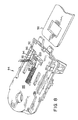
- FIG. 8 An alternative embodiment seat belt buckle 84 is shown in Fig. 8.
- the seat belt buckle 84 has a body 86 similar to the body shown in Fig. 1, except that an opening 88 is formed adjacent to and continuous with a transverse slot 90.
- a sensor housing 92 is positioned in the opening 88.
- the sensor housing 92 incorporates a GMR sensor 95 on a circuit board 94 and a magnet 96 spaced a short distance from the GMR sensor 95.
- the GMR sensor 95 and the magnet 96 are positioned so that when the hasp 98 is engaged with the buckle 84 both the magnet 96 and the GMR sensor 95 engage or are closely spaced from the hasp 98. In this way the GMR sensor 95 directly detects the presence of the hasp 98.
- the motion of the latch 100 through the transverse slot 90 is also sufficiently close to the gap between the magnet 96 and the GMR sensor that the presence of the latch 100 can also be directly sensed.
- a conventional buckle with a two-position motion of the latch 100 as illustrated in Figs. 4 and 5, can be employed.
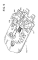
- FIG. 9 Another alternative embodiment seat belt buckle and sensor assembly 102 is shown in Fig. 9.
- This embodiment uses the three-step motion illustrated in Figs. 6 and 7.
- the device 102 has a GMR sensor package 104 which contains a magnet 106 and a GMR sensor 108 which is positioned behind the latch 110.
- the ferromagnetic latch 110 moves into and out of a gap 112 between the sensor 108 and the magnet 106.
- the displacement of the latch 110 away from the gap 112 results in decreased magnetic field strength at the sensor 108.
- the three states unlatched, latched with hasp present, shown in Fig. 6, and latched with hasp not present, shown in Fig. 7, can be differentiated.
- GMR sensor can be used with a reference voltage or current
- the change in resistance of one or more GMR resistances can be determined directly with a circuit which functions as an ohmmeter.
- the gap between the GMR sensor and the magnet reduces the magnetic field strength sensed by the GMR sensor and that movement of a component of the seat belt buckle towards or away from, the gap is hereby defined as movement with respect to the magnet and the sensor which changes the sensed magnetic field.
- This movement may generally be a motion which physically fills the gap with a ferromagnetic body such that lines of magnetic flux are concentrated and thus the sensor reads a higher magnetic field.
- the reverse action of removing a ferromagnetic body from the gap will reduce the magnetic field read by the sensor.
- Such motions could include removal of a magnetic shunt, and motion of some part of a component towards and some part away from the physical gap.
Landscapes
- Engineering & Computer Science (AREA)
- Automation & Control Theory (AREA)
- Mechanical Engineering (AREA)
- Physics & Mathematics (AREA)
- General Physics & Mathematics (AREA)
- Buckles (AREA)
- Automotive Seat Belt Assembly (AREA)
Description
Claims (5)
- A seat belt buckle and latch indicator sensor comprising:characterized in thata seat belt buckle (20);a seat belt (40);a seat belt hasp (38) connected to the seat belt, the hasp fitting within the seat belt buckle to releasably connect the seat belt to the buckle;a latch (26) formed of ferromagnetic material mounted within the seat belt buckle, the latch being movable between an unlatched position and a latched position in which the seat belt hasp is mechanically retained within the seat belt buckle;a magnetic field sensor (46) fixedly mounted to the seat belt buckle; anda magnet (50) having a magnetic field, the magnet being spaced from the magnetic field sensor and fixedly mounted to the seat belt buckle, the magnet and the sensor defining à gap (54, 112) therebetween, wherein the movement of the latch between the unlatched position and the latched position is such that latching of the seat belt buckle changes the magnetic field sensed by the sensor,
the latch (26) is movable between three positions, comprised of an unlatched position, a latched position and a latch-without-a-hasp-present position, and wherein the latched position is closer to the gap (54, 112) than the unlatched position, and the latched-without-a-hasp position is closer to the gap than the latched position. - The seat belt buckle and latch indicator of Claim 1 wherein the magnetic field sensor (46) is of the GMR type.
- The seat belt buckle and latch indicator of Claim 1 further comprising a ferromagnetic body (22), the body forming a hole for attaching the seat belt to a vehicle, the body defining an opening (80) through which the latch moves, wherein the magnetic field sensor (46) is positioned on one side of the opening through which the latch moves and the magnet (50) is positioned on an opposite side so that the opening defines the gap between the sensor and the magnet.
- The seat belt buckle and latch indicator of Claim 1 further comprising a ferromagnetic body (22), the body beginning a hole for attaching the seat belt (40) to a vehicle, the body forming an opening (80) through which the latch (26) moves, and wherein the body also defines an opening through the body and positioned to overlie the seat belt hasp (38) when the hasp is within the seat belt buckle, wherein the magnetic field sensor is mounted through the opening adjacent the hasp, and wherein the magnet (50) which is spaced from the magnetic field sensor is also mounted through the opening adjacent the hasp.
- The seat belt buckle and latch indicator of Claim 1 wherein the magnetic field sensor (46) and magnet (50) are positioned so that movement of the latch (26) between the unlatched position and the latched position moves a portion of the latch away from the gap such that latching of the seat belt buckle (20) decreases the magnetic field sensed by the sensor.
Applications Claiming Priority (3)
| Application Number | Priority Date | Filing Date | Title |
|---|---|---|---|
| US09/065,684 US6079744A (en) | 1998-04-24 | 1998-04-24 | Device to detect seat belt buckle status |
| US65684 | 1998-04-24 | ||
| PCT/US1999/002230 WO1999055561A1 (en) | 1998-04-24 | 1999-02-02 | Device to detect seat belt buckle status |
Publications (2)
| Publication Number | Publication Date |
|---|---|
| EP1071587A1 EP1071587A1 (en) | 2001-01-31 |
| EP1071587B1 true EP1071587B1 (en) | 2003-10-29 |
Family
ID=22064421
Family Applications (1)
| Application Number | Title | Priority Date | Filing Date |
|---|---|---|---|
| EP99905642A Expired - Lifetime EP1071587B1 (en) | 1998-04-24 | 1999-02-02 | Device to detect seat belt buckle status |
Country Status (7)
| Country | Link |
|---|---|
| US (1) | US6079744A (en) |
| EP (1) | EP1071587B1 (en) |
| JP (1) | JP3598326B2 (en) |
| KR (1) | KR100473971B1 (en) |
| CA (1) | CA2324508C (en) |
| DE (1) | DE69912415T2 (en) |
| WO (1) | WO1999055561A1 (en) |
Cited By (1)
| Publication number | Priority date | Publication date | Assignee | Title |
|---|---|---|---|---|
| DE102004011299A1 (en) * | 2004-03-09 | 2005-10-06 | Hirschmann Automotive Gmbh | buckle |
Families Citing this family (33)
| Publication number | Priority date | Publication date | Assignee | Title |
|---|---|---|---|---|
| BR9911893A (en) * | 1998-07-07 | 2001-03-27 | Trw Automotive Electron & Comp | Device for monitoring the locking position of a connecting device, especially the locking position of a device for attaching a child seat to a vehicle |
| JP3458351B2 (en) * | 1999-09-21 | 2003-10-20 | タカタ株式会社 | buckle |
| JP4567835B2 (en) * | 2000-02-18 | 2010-10-20 | 株式会社東海理化電機製作所 | Buckle device |
| US6400145B1 (en) | 2000-05-04 | 2002-06-04 | Breed Automotive Technology, Inc. | Seat belt tension sensor, methods of integration and attachment |
| US6389661B1 (en) * | 2000-05-25 | 2002-05-21 | Trw Vehicle Safety Systems Inc. | Latch sensing seatbelt buckle |
| DE10026444C2 (en) * | 2000-05-30 | 2002-04-04 | Autoliv Dev | Seat belt system with a measuring arrangement for determining the webbing force |
| CA2358762A1 (en) | 2000-10-11 | 2002-04-11 | Steven R. Takayama | Car seat having looped adjustable shoulder harness |
| DE10127058A1 (en) * | 2001-06-02 | 2002-12-05 | Bosch Gmbh Robert | Automobile seat occupant classification device combines signal from force sensor for passenger seat belt with seat belt closure switch signal |
| US6819233B2 (en) | 2001-08-13 | 2004-11-16 | Alan L. Beaty | Prisoner escape seat belt detection and alert system |
| DE10146630A1 (en) | 2001-09-21 | 2003-04-10 | Bosch Gmbh Robert | Device for belt force and belt usage detection |
| JP3869247B2 (en) * | 2001-10-29 | 2007-01-17 | 株式会社東海理化電機製作所 | Buckle device |
| US6448907B1 (en) | 2002-01-18 | 2002-09-10 | Nicholas J. Naclerio | Airline passenger management system |
| JP3961920B2 (en) * | 2002-09-27 | 2007-08-22 | 株式会社東海理化電機製作所 | Buckle device |
| DE10255324A1 (en) * | 2002-11-27 | 2004-06-17 | Cherry Gmbh | Device for querying the locking status of a belt buckle for vehicles |
| US6965231B1 (en) | 2003-10-31 | 2005-11-15 | Fonar Corporation | Belt buckle and use thereof in magnetic resonance imaging |
| US20050092546A1 (en) * | 2003-11-04 | 2005-05-05 | Hsu Samuel W. | Safety belt device having warning device |
| US20060061201A1 (en) * | 2004-09-21 | 2006-03-23 | Skinner Charles W | Seat belt restraint and alarm system and method of use thereof |
| US9179758B2 (en) * | 2005-12-16 | 2015-11-10 | Kolcraft Enterprises, Inc. | Child carriers and methods for operating the same |
| KR100844427B1 (en) | 2007-09-04 | 2008-07-08 | 현대자동차주식회사 | Seat belt wearing detection system and method and method |
| JP5207227B2 (en) * | 2007-09-26 | 2013-06-12 | 勲 湯浅 | Collagen production promoter |
| US7770929B2 (en) * | 2008-04-22 | 2010-08-10 | Freescale Semiconductor, Inc. | Vehicular seatbelt restraint with selectively disabled inertia reel assembly |
| US8333433B2 (en) | 2010-02-10 | 2012-12-18 | Friedman Mark J | Locking harness apparatus and method |
| US20120104826A1 (en) * | 2010-09-15 | 2012-05-03 | Amsafe Commercial Products, Inc. | Occupant restraint system components having status indicators and/or media interfaces, and associated methods of use and manufacture |
| CH708643A2 (en) * | 2013-09-25 | 2015-03-31 | Polycontact Ag | Buckle with Hall sensor. |
| US9781977B2 (en) | 2015-08-11 | 2017-10-10 | Shield Restraint Systems, Inc. | Interlocking web connectors for occupant restraint systems and associated methods of use and manufacture |
| US10357083B2 (en) | 2016-09-16 | 2019-07-23 | Shield Restraint Systems, Inc. | Buckle assemblies and associated systems and methods for use with child seats and other restraint systems |
| US10264895B2 (en) | 2017-02-22 | 2019-04-23 | Kolcraft Enterprises, Inc. | Adjustable child carriers |
| US10857916B2 (en) * | 2017-04-13 | 2020-12-08 | Chad Glerum | Seat belt tension indicator |
| US10703327B2 (en) * | 2018-02-07 | 2020-07-07 | Ford Global Technologies, Llc | Seatbelt assembly |
| US11124152B2 (en) | 2018-11-20 | 2021-09-21 | Shield Restraint Systems, Inc. | Buckle assemblies for use with child seats and other personal restraint systems |
| US12448817B2 (en) | 2021-02-03 | 2025-10-21 | Ashored Inc. | Magnetic release mechanism |
| US12451279B2 (en) | 2021-02-03 | 2025-10-21 | Ashored Inc. | Magnetic release mechanism |
| US12330584B1 (en) * | 2024-05-31 | 2025-06-17 | GM Global Technology Operations LLC | Height adjustable seatbelt buckle |
Family Cites Families (26)
| Publication number | Priority date | Publication date | Assignee | Title |
|---|---|---|---|---|
| US3766612A (en) * | 1972-05-02 | 1973-10-23 | Tokai Rika Co Ltd | Seat belt buckle provided with a switch means |
| FR2468486A1 (en) * | 1979-10-30 | 1981-05-08 | Smadja Francois | Seat belt operated starter motor connecting device - has switch, linking starter motor to battery, operated by seat belt buckling mechanism |
| DE3605179A1 (en) * | 1986-02-19 | 1987-08-20 | Standard Elektrik Lorenz Ag | PROXIMITY SENSOR |
| US4668552A (en) * | 1986-07-28 | 1987-05-26 | Collins & Aikman Corporation | Wrap yarns having low-melt binder strands and pile fabrics formed therefrom and attendant processes |
| JPS6340045A (en) * | 1986-07-31 | 1988-02-20 | 株式会社長谷工コーポレーション | X-shaped wiring structure of column |
| FR2630984B1 (en) * | 1988-05-06 | 1991-04-12 | Ecia Equip Composants Ind Auto | SIMPLIFIED IMPROVED BUCKLE FOR SEAT BELT |
| DE3904668A1 (en) * | 1989-02-16 | 1990-08-30 | Daimler Benz Ag | Passenger restraint system |
| JPH02227348A (en) * | 1989-03-01 | 1990-09-10 | Nippon Seiko Kk | Magnet built-in parts for vehicle rider protector |
| DE3908993A1 (en) * | 1989-03-18 | 1990-09-20 | Daimler Benz Ag | DEVICE FOR MONITORING THE CORRECT FUNCTION OF A SWITCH COMPONENT INQUIRING THE LOCKING STATE OF A BELT LOCK IN A MOTOR VEHICLE |
| JPH038045U (en) * | 1989-06-12 | 1991-01-25 | ||
| DE4032757A1 (en) * | 1990-10-16 | 1992-04-23 | Daimler Benz Ag | VEHICLE WITH A BELT AND AIRBAG SYSTEM |
| US5133425A (en) * | 1990-11-29 | 1992-07-28 | Han Chong K | Passive seat belt system |
| DE69300433T2 (en) * | 1992-03-24 | 1996-03-21 | Univ Teesside | Seat belt warning device. |
| US5675134A (en) * | 1992-05-25 | 1997-10-07 | Siemens Aktiengesellschaft | Traffic accident detecting sensor for a passenger protection system in a vehicle |
| US5483221A (en) * | 1993-11-12 | 1996-01-09 | Ford Motor Company | Seat belt usage indicating system |
| US5752986A (en) * | 1993-11-18 | 1998-05-19 | Nec Corporation | Method of manufacturing a solid electrolytic capacitor |
| DE9317678U1 (en) * | 1993-11-19 | 1995-03-16 | Autoliv Development AB, Vårgårda | Vehicle security system |
| DE19505334C2 (en) * | 1995-02-17 | 2003-08-14 | Bosch Gmbh Robert | Electronic device |
| US5590904A (en) * | 1995-08-15 | 1997-01-07 | Trw Vehicle Safety Systems Inc. | Dual resistance switch for buckle confirmation |
| US5752299A (en) * | 1996-05-06 | 1998-05-19 | Alliedsignal Inc. | Seat belt buckle with usage indicator |
| JPH09329461A (en) * | 1996-06-10 | 1997-12-22 | Mitsubishi Electric Corp | Detector |
| DE19630108A1 (en) * | 1996-07-25 | 1998-01-29 | Siemens Ag | Contact free speed or position detector for ferromagnetic generator part |
| US5742986A (en) * | 1997-02-13 | 1998-04-28 | Trw Inc. | Seat belt buckle with hall effect locking indicator and method of use |
| US5839174A (en) * | 1997-06-13 | 1998-11-24 | Breed Automotive Technology, Inc. | Seat belt buckle |
| US5966784A (en) * | 1997-07-25 | 1999-10-19 | Trw Inc. | Method and apparatus for indicating the locked or unlocked condition of a seat belt buckle |
| US5898366A (en) * | 1997-09-23 | 1999-04-27 | Trw Vehicle Safety Systems Inc. | Seat belt buckle with Hall effect locking indicator |
-
1998
- 1998-04-24 US US09/065,684 patent/US6079744A/en not_active Expired - Fee Related
-
1999
- 1999-02-02 EP EP99905642A patent/EP1071587B1/en not_active Expired - Lifetime
- 1999-02-02 KR KR10-2000-7011644A patent/KR100473971B1/en not_active Expired - Fee Related
- 1999-02-02 DE DE69912415T patent/DE69912415T2/en not_active Expired - Fee Related
- 1999-02-02 CA CA002324508A patent/CA2324508C/en not_active Expired - Fee Related
- 1999-02-02 JP JP2000545732A patent/JP3598326B2/en not_active Expired - Fee Related
- 1999-02-02 WO PCT/US1999/002230 patent/WO1999055561A1/en not_active Ceased
Cited By (1)
| Publication number | Priority date | Publication date | Assignee | Title |
|---|---|---|---|---|
| DE102004011299A1 (en) * | 2004-03-09 | 2005-10-06 | Hirschmann Automotive Gmbh | buckle |
Also Published As
| Publication number | Publication date |
|---|---|
| EP1071587A1 (en) | 2001-01-31 |
| JP3598326B2 (en) | 2004-12-08 |
| KR100473971B1 (en) | 2005-03-07 |
| JP2002512918A (en) | 2002-05-08 |
| WO1999055561A1 (en) | 1999-11-04 |
| CA2324508A1 (en) | 1999-11-04 |
| KR20010042870A (en) | 2001-05-25 |
| US6079744A (en) | 2000-06-27 |
| DE69912415T2 (en) | 2004-07-22 |
| DE69912415D1 (en) | 2003-12-04 |
| CA2324508C (en) | 2006-04-11 |
Similar Documents
| Publication | Publication Date | Title |
|---|---|---|
| EP1071587B1 (en) | Device to detect seat belt buckle status | |
| EP1150584B1 (en) | Seat belt buckle sensor | |
| US6081759A (en) | Seat belt tension sensor | |
| EP1272376B1 (en) | Seat belt tension sensing device | |
| EP0861763B1 (en) | Seat belt buckle with hall effect locking indicator and method of use | |
| US6843143B2 (en) | Seat belt tension sensor | |
| US6825654B2 (en) | Airbag deployment monitor and sensing electronics | |
| US20040227626A1 (en) | Seat belt latch sensor assembly | |
| US8613470B2 (en) | Seat belt system with buckle latch and tension sensor | |
| US7014005B2 (en) | Seat belt latch sensor assembly | |
| EP1032285B1 (en) | Seat belt buckle | |
| US6895643B2 (en) | Buckle device | |
| US8547217B2 (en) | Belt lock with status detector | |
| US6889408B2 (en) | Buckle apparatus | |
| US6737862B1 (en) | Magnetosensitive latch engagement detector for a mechanical fastening system | |
| US8610011B2 (en) | Belt lock with a switch arrangement for detection of the locking status | |
| CN107107851B (en) | Detect movement of seat belt sensor | |
| EP1125802B1 (en) | Buckle Device | |
| CN113525290A (en) | Pop-up element with trigger for seat belt buckle sensor | |
| US20030122361A1 (en) | Seat restraint tension sensing assembly | |
| US7159686B2 (en) | Apparatus and method for detection of a latching device | |
| WO2022187298A1 (en) | Seatbelt buckle system and method for detecting a latch in a seatbelt buckle |
Legal Events
| Date | Code | Title | Description |
|---|---|---|---|
| PUAI | Public reference made under article 153(3) epc to a published international application that has entered the european phase |
Free format text: ORIGINAL CODE: 0009012 |
|
| 17P | Request for examination filed |
Effective date: 20000616 |
|
| AK | Designated contracting states |
Kind code of ref document: A1 Designated state(s): DE ES FR GB IT SE |
|
| 17Q | First examination report despatched |
Effective date: 20020807 |
|
| GRAH | Despatch of communication of intention to grant a patent |
Free format text: ORIGINAL CODE: EPIDOS IGRA |
|
| GRAS | Grant fee paid |
Free format text: ORIGINAL CODE: EPIDOSNIGR3 |
|
| GRAA | (expected) grant |
Free format text: ORIGINAL CODE: 0009210 |
|
| AK | Designated contracting states |
Kind code of ref document: B1 Designated state(s): DE ES FR GB IT SE |
|
| REG | Reference to a national code |
Ref country code: GB Ref legal event code: FG4D |
|
| REF | Corresponds to: |
Ref document number: 69912415 Country of ref document: DE Date of ref document: 20031204 Kind code of ref document: P |
|
| PG25 | Lapsed in a contracting state [announced via postgrant information from national office to epo] |
Ref country code: SE Free format text: LAPSE BECAUSE OF FAILURE TO SUBMIT A TRANSLATION OF THE DESCRIPTION OR TO PAY THE FEE WITHIN THE PRESCRIBED TIME-LIMIT Effective date: 20040129 |
|
| PG25 | Lapsed in a contracting state [announced via postgrant information from national office to epo] |
Ref country code: ES Free format text: LAPSE BECAUSE OF FAILURE TO SUBMIT A TRANSLATION OF THE DESCRIPTION OR TO PAY THE FEE WITHIN THE PRESCRIBED TIME-LIMIT Effective date: 20040209 |
|
| ET | Fr: translation filed | ||
| PLBE | No opposition filed within time limit |
Free format text: ORIGINAL CODE: 0009261 |
|
| STAA | Information on the status of an ep patent application or granted ep patent |
Free format text: STATUS: NO OPPOSITION FILED WITHIN TIME LIMIT |
|
| 26N | No opposition filed |
Effective date: 20040730 |
|
| REG | Reference to a national code |
Ref country code: GB Ref legal event code: 732E |
|
| REG | Reference to a national code |
Ref country code: FR Ref legal event code: TP |
|
| PGFP | Annual fee paid to national office [announced via postgrant information from national office to epo] |
Ref country code: IT Payment date: 20080223 Year of fee payment: 10 Ref country code: GB Payment date: 20080108 Year of fee payment: 10 |
|
| PGFP | Annual fee paid to national office [announced via postgrant information from national office to epo] |
Ref country code: FR Payment date: 20080212 Year of fee payment: 10 |
|
| PGFP | Annual fee paid to national office [announced via postgrant information from national office to epo] |
Ref country code: DE Payment date: 20090227 Year of fee payment: 11 |
|
| GBPC | Gb: european patent ceased through non-payment of renewal fee |
Effective date: 20090202 |
|
| REG | Reference to a national code |
Ref country code: FR Ref legal event code: ST Effective date: 20091030 |
|
| PG25 | Lapsed in a contracting state [announced via postgrant information from national office to epo] |
Ref country code: GB Free format text: LAPSE BECAUSE OF NON-PAYMENT OF DUE FEES Effective date: 20090202 Ref country code: FR Free format text: LAPSE BECAUSE OF NON-PAYMENT OF DUE FEES Effective date: 20090302 |
|
| PG25 | Lapsed in a contracting state [announced via postgrant information from national office to epo] |
Ref country code: DE Free format text: LAPSE BECAUSE OF NON-PAYMENT OF DUE FEES Effective date: 20100901 |
|
| PG25 | Lapsed in a contracting state [announced via postgrant information from national office to epo] |
Ref country code: IT Free format text: LAPSE BECAUSE OF NON-PAYMENT OF DUE FEES Effective date: 20090202 |