EP1071556B1 - A paperboard core with an improved chuck strength, for the paper industry, and a method of fabricating such - Google Patents
A paperboard core with an improved chuck strength, for the paper industry, and a method of fabricating such Download PDFInfo
- Publication number
- EP1071556B1 EP1071556B1 EP99901607A EP99901607A EP1071556B1 EP 1071556 B1 EP1071556 B1 EP 1071556B1 EP 99901607 A EP99901607 A EP 99901607A EP 99901607 A EP99901607 A EP 99901607A EP 1071556 B1 EP1071556 B1 EP 1071556B1
- Authority
- EP
- European Patent Office
- Prior art keywords
- core
- paperboard
- ply
- inside diameter
- cylindrical surface
- Prior art date
- Legal status (The legal status is an assumption and is not a legal conclusion. Google has not performed a legal analysis and makes no representation as to the accuracy of the status listed.)
- Expired - Lifetime
Links
Images


Classifications
-
- B—PERFORMING OPERATIONS; TRANSPORTING
- B65—CONVEYING; PACKING; STORING; HANDLING THIN OR FILAMENTARY MATERIAL
- B65H—HANDLING THIN OR FILAMENTARY MATERIAL, e.g. SHEETS, WEBS, CABLES
- B65H75/00—Storing webs, tapes, or filamentary material, e.g. on reels
- B65H75/02—Cores, formers, supports, or holders for coiled, wound, or folded material, e.g. reels, spindles, bobbins, cop tubes, cans, mandrels or chucks
- B65H75/04—Kinds or types
- B65H75/08—Kinds or types of circular or polygonal cross-section
- B65H75/10—Kinds or types of circular or polygonal cross-section without flanges, e.g. cop tubes
-
- B—PERFORMING OPERATIONS; TRANSPORTING
- B31—MAKING ARTICLES OF PAPER, CARDBOARD OR MATERIAL WORKED IN A MANNER ANALOGOUS TO PAPER; WORKING PAPER, CARDBOARD OR MATERIAL WORKED IN A MANNER ANALOGOUS TO PAPER
- B31C—MAKING WOUND ARTICLES, e.g. WOUND TUBES, OF PAPER, CARDBOARD OR MATERIAL WORKED IN A MANNER ANALOGOUS TO PAPER
- B31C3/00—Making tubes or pipes by feeding obliquely to the winding mandrel centre line
-
- Y—GENERAL TAGGING OF NEW TECHNOLOGICAL DEVELOPMENTS; GENERAL TAGGING OF CROSS-SECTIONAL TECHNOLOGIES SPANNING OVER SEVERAL SECTIONS OF THE IPC; TECHNICAL SUBJECTS COVERED BY FORMER USPC CROSS-REFERENCE ART COLLECTIONS [XRACs] AND DIGESTS
- Y10—TECHNICAL SUBJECTS COVERED BY FORMER USPC
- Y10T—TECHNICAL SUBJECTS COVERED BY FORMER US CLASSIFICATION
- Y10T428/00—Stock material or miscellaneous articles
- Y10T428/13—Hollow or container type article [e.g., tube, vase, etc.]
- Y10T428/1303—Paper containing [e.g., paperboard, cardboard, fiberboard, etc.]
Definitions
- the present invention relates to a method according to preamble of claim 1, of fabricating paperboard cores for the paper industry, said paperboard cores having an improved chuck strength and thick walls, the wall thickness H being 10 mm or more and the inside diameter over 70 mm.
- Such cores are used at winding/unwinding speeds of at least about 200 m/min (3.3 m/s).
- the invention also relates to a method of fabricating other paperboard cores of similar dimensions, which call for high chuck strength.
- the invention further relates to a spirally wound, thick-walled core constructed by this method.
- Cores used by the printing and paper converting industries are herein referred to as paper industry cores.
- Such cores are thick-walled, having a wall thickness H which is at least 10 mm and an inside diameter which is over 70 mm.
- a spiral paperboard core is made up of a plurality of superimposed plies of paperboard by winding, glueing, and drying such.
- Webs produced in the paper, film, and textile industries are usually reeled on cores for rolls.
- Cores made from paperboard, especially spiral cores are fabricated by glueing plies of paperboard one on top of the other and by winding them spirally in a special spiral machine.
- the width, thickness, and number of paperboard plies needed to form a core vary depending on the dimensions and strength requirements of the core to be manufactured. Typically, the ply width is 50 to 250 mm (in special cases about 500 mm), ply thickness about 0.2 to 1.2 mm, and the number of plies about 3 to 30 (in special cases about 50).
- the strength of a paperboard ply varies to comply with the strength requirement of the core. As a general rule, increasing the strength of a paperboard ply also increases its price. Generally speaking, it is therefore true to say that the stronger the core, the more expensive it is.
- weights of paper rolls used e.g., in printing presses have been on a continuous increase, which calls for a higher and higher strength and a higher and higher capacity of spiral cores.
- the weights of paper rolls vary considerably, from newspaper and fine paper rolls of 600-1800 kg to rotogravure rolls of about 2400-5500 kg.
- the biggest rolls that have been made, for testing purposes, have weighed about 6500 kg.
- the diameters of big paper rolls are then typically 1.24 to 1.26 m at most
- Printing presses typically use cores of two sizes.
- the most usual core size has an inside diameter of 76 mm (3") and a thickness of 13 or 15 mm.
- Printing presses are being designed which should handle paper rolls having a diameter of 1.35 m; estimates have been presented of even 1.5 m rolls. As the roll width increases to 3.6 m, the weight of a paper roll will increase considerably, to more than 6.5 tons, even to 8.5 tons.
- Typical ply widths of paperboard cores used in the printing and paper converting industries, as discussed above, are about 120 to 150 mm with cores having the inside diameter of 76 mm (3"), which is the most commonly used inside diameter, and up to 190 mm with cores having the inside diameter of 150 mm (6").
- the wall thicknesses of paperboard cores are typically about 10 to 20 mm. The definition of the average winding angle ⁇ is presented in Fig. 3 below.
- Paper reels are formed on a winding core. Almost always this winding core is a spirally wound paperboard core.
- the requirement of a good chuck strength is emphasized especially in, e.g., shaftless winding/unwinding of a paper web, where the core, serving as the only shaft, bears the weight of the paper roll either partly or completely through short chucks of about 50 to 250 mm in length.
- the chuck may be subject to a pressure of accelerating belts needed for an automatic reel change in the printing press. These accelerating belts may cause an extra strain of even 1 to 2 tons on the core.
- the chuck strength is an essential requirement at the paper mill in making the roll, when slitter winders of the so-called centre winder type are used.
- cores are subject to different stresses when they are used, e.g., in a paper roll.
- the core serves as the only shaft, supporting the weight of the paper roll either entirely or partly, through a short chuck.
- the z-direction here means a direction perpendicular to the surface level of a paperboard ply, i.e., in the cross section of a finished core, it is the direction of the core radius.
- the z-direction maximum tensile and shear stresses directed to the plies are radial, occurring near the middle of the core wall, slightly inwardly therefrom.
- EP 0 627 306 B1 discloses a multi-grade paperboard tube having enhanced crush strength.
- a multi-grade multiple ply paperboard tube has the plies positioned within the wall of the tube at locations for enhancement of the flat crush strength.
- the respective plies have different densities.
- US 3,194,275 describes a spirally wound paper tube for the winding of sheet material.
- the paper tube comprises a plurality of fibre containing paper strips spirally wound in overlapping relationship with adhesive therebetween to form a spiral tube, each of the paper strips having its fibres lying generally in the direction of the longitudinal axis of these strips. These strips are wound at a winding angle of between about 15 to 25 degrees thereby providing a dimensionally stable tube of high beam strength and crush strength.
- An object of the present invention is to provide an improved and more efficient method of fabricating thick-walled paperboard cores for the paper industry, the wall thickness being over 10 mm and the inside diameter over 70 mm.
- Another object of the present invention is to provide an improved method of increasing the chuck strength of both thick-walled paperboard cores for the paper industry, which have a wall thickness of over 10 mm and an inside diameter of over 70 mm, and other paperboard cores which require high chuck strength, and at the same time to provide a novel type of thick-walled spiral paperboard core which has better properties in use.
- a further object of the present invention is to solve problems related to the above discussed thick-walled spiral cores presently in use and to offer a solution for meeting the requirements set by ever increasing roll weights, especially on the chuck strength of cores.
- typical wall thickness - inside diameter figures are, e.g., 15 mm x 76 mm and 13 mm x 150 mm.
- Stresses caused by chuck loading on the biggest cores, such as, e.g., 13 mm x 300 mm (10 mm x 300 mm) are naturally lower than on paper industry cores having a smaller diameter, due to the core geometry.
- the chuck strength of, for example, 13 x 300 mm core is in itself higher than the chuck strength of cores having a small diameter. This is because, due to a big inside diameter, the bearing area of the core with respect to the shaft is large.
- the present invention does not relate to paperboard cores which have a wall thickness less than 10 mm.
- Paper industry cores must have a thick wall, i.e., more than 10 mm in order to enable them to be clamped by chucks (chuck expansion) and in order to enable formation of a nip between the core surface and a backing roll.
- chucks chuck expansion
- winders and slitter-winders calls for a sufficient wall thickness of cores, 10 mm or more, in practice.
- the arrangement of the present invention increases the production rate of all paper industry cores with different diameters, but its advantages as to the increase of chuck strength is pronounced with paper industry cores of small diameters.
- the greatest significance of an improved chuck strength is established in connection with most commonly used cores which have the inside diameter of 3" (about 76 mm).
- a significant improvement of the chuck strength is achieved also with cores having the inside diameter of 6" (about 150 mm).
- the arrangement according to the present invention is also applicable to the fabrication of other paperboard cores, which require high chuck strength and which have similar dimensions as the cores according to the present invention, used in the printing and paper converting industries.
- the present invention deals with core breaking, caused by a crack breaking mechanism.
- core breaking caused by a crack breaking mechanism.
- the break of a core occurs in the cylindrical surface within the core wall and/or in the vicinity thereof, in which cylindrical surface the maximum stresses are to be found. Therefore, we have presented the widths and web edge lengths of the core ply on the level of the cylindrical surface and in the vicinity thereof, as attributes describing our invention.
- corresponding definitions could be made with respect to the interior or exterior plies, the dimensions of which are determined by selecting the structural dimensions of the core and by fixing, on the maximum stress surface, the ply length per linear meter of core or the ply width.
- the arrangement according to the invention for improving the chuck strength of thick-walled paperboard cores for the paper industry, makes use of, e.g., the following discoveries.
- the basic idea of our invention is to reduce the length of the gaps per linear metre of the core, thereby providing a paper industry core, which has less than before of web edge line of ply per linear metre, i.e., fewer potential points of initial cracks per linear metre of the core than before.
- the idea of the present invention is to provide a structure for a thick-walled paper industry core, which is suitable for exacting chuck load conditions and which has a shorter length of gaps per linear metre of the core than prior art arrangements of paper industry cores. This is brought about by growing the width of the paperboard plies used in the core fabrication. When the number of gaps, i.e., the number of potential points for initial cracks is reduced per length unit, on the basis of the above discovery, this will result in a growth of core capacity, in other words, the chuck strength and load bearing capacity.
- core capacity in other words, the chuck strength and load bearing capacity.
- wider plies than before are used in a core having a certain inside diameter. The inside diameter and the wall thickness of a core again influence the width gradation of the plies to be used.
- Fig. 1a is a schematic side view of a prior art 13 mm x 150 mm core.
- the middle ply web edge length per core metre is about 3340 mm in this core when the ply width is about 154 mm.
- Fig. 1 b is a schematic side view of a second, commonly used prior art 15 mm x 76 mm core.
- the middle ply web edge length per metre of this core is about 1914 mm when the ply width is about 150 mm.
- Fig. 1c is a schematic side view of a 13 mm x 150 mm core in accordance with the present invention.
- the middle ply web edge length per metre of this core is about 1410 mm when the ply width is about 364 mm.
- the middle ply web edge length of about 1410 mm corresponds to about 203 mm wide middle ply.
- Fig. 1d is a schematic side view of a second 13 mm x 150 mm core in accordance with the present invention.
- the middle ply web edge length per metre of this core is about 1154 mm when the ply width is about 445 mm.
- the middle ply web edge length of about 1152 mm corresponds to about 249 mm wide middle ply.
- Paper industry cores of different inside diameters are characterized in the accompanying claims using the reference values characteristic of each core size.
- the z-direction stress maximum in the wall of a finished paperboard core is located near the middle of the core wall, slightly towards the inner surface of the core.
- the cylindrical surface representing the z-direction stress maximum in the core wall is not exactly in the middle of the wall, the structural conditions and measure parameters are, however, practically almost identical.
- the surrounding plies including the one in the middle of the wall, have almost the same theoretical width, as can be seen in Table 1.
- Table 1 shows a theoretical study on the ply widths of a 13x150 mm core, which has been constructed, according to prior art, of 25 plies, each ply being 0.53 mm thick.
- the ply widths are reported starting from interior ply 1, and the width of the exterior ply has been selected to be 155 mm.
- the denotation 13x150 mm refers to a core having the wall thickness of 13 mm and inside diameter of 150 mm.
- the stress maximum is located at about plies 10 - 11, where the average of the ply + gap is 153.837 mm.
- the middle of the core wall is situated at ply 13, where the ply + gap together make 154.066.
- the widths of the ply + gap in both the point of stress maximum and the middle of the core wall are almost equal.
- every ply does not receive a width of its own, but only a few ply widths are selected for making up a core.
- a 13x150 mm core is typically constructed of plies of two different widths, i.e., 154 mm and 155 mm.
- the web edge length of the structural ply in the middle of the core wall is 3340 mm in a 1 m long core, as can be seen in Table 1.
- the difference between the web edge length of the structural ply in the stress maximum and the web edge length of the ply in the middle of the core wall is about 50 mm.
- a corresponding review could also be made with a commonly used core, which has the inside diameter of 76 mm.
- Paperboard cores constructed according to the present invention are used at reeling speeds which are at least about 200 m/min (3.3 m/s). Paperboard cores according to the present invention are advantageous at winding/unwinding speeds of 800 - 900 m/min and even higher, up to about 2500 m/min. The wider the paperboard ply is, the less it has of potential web edge per length unit, e.g., linear metre, where initial cracks could concentrate.
- the advantages of the present invention are emphasized also in connection with heavier roll weights and smaller cores, especially with cores having the inside diameter of 76 mm.
- the present invention provides a clear improvement in the runnability of cores used at the widest and fastest printing presses, i.e., where the rolls are the heaviest, and enables construction of such paper industry cores that meet the demands set by the new dimensions of paper rolls being designed.
- Printing presses being designed are to handle paper rolls of 1.35 m in diameter; estimates have been presented of paper rolls having a diameter of even up to 1.5 m.
- the roll widths of such printing presses will be as big as 3.6 m, whereby the weights of the paper rolls will increase considerably, to more than 6.5 tons, even to 8.5 tons.
- the present invention provides a worthwhile and advantageous arrangement for a core construction to meet these challenges.
- a spiral paperboard core is fabricated by using, on the cylindrical surface representing the z-direction stress maximum in the wall of a finished paperboard core, and in the vicinity of said cylindrical surface, including the paperboard ply in the middle of the core wall, ply widths which are, with the inside diameter of the paperboard core being
- Spiral paperboard cores of 76 mm (3") and 150 mm (6") which are commonly used, especially in the paper industry, are fabricated, according to the present invention, by winding paperboard plies spirally around a mandrel into a tube, whereby the following applies on the cylindrical surface representing the z-direction stress maximum in the wall of a finished paperboard core, and in the vicinity of said cylindrical surface, including the paperboard ply in the middle of the core wall, in a 1 m long paperboard core,
- a spiral paperboard core is fabricated by using, on the cylindrical surface representing the z-direction stress maximum in the wall of a finished paperboard core, and in the vicinity of said cylindrical surface, including the paperboard ply in the middle of the core wall, ply widths which are
- Paperboard cores for the paper industry are used at winding or'unwinding speeds of at least about 200 m/min (3.3 m/s). Paperboard cores according to the present invention are advantageous at winding/unwinding speeds which are higher than about 300 m/min (5 m/s), typically about 800-900 m/min and even more, up to about 2500 m/min.
- the arrangement of the present invention provides a paper industry core having an improved chuck strength, which core is thick-walled, the wall thickness H being 10 mm or more, and the inside diameter over 70 mm.
- the arrangement of the present invention is advantageous also for improving the chuck strengths of paperboard cores which have similar dimensions and which call for high chuck strength.
- the middle ply width of a paperboard core is, however, 230 mm to 550 mm, depending on the core diameter.
- the advantages of the present invention are naturally emphasized with wide plies. However, for reasons related to fabricating technique, it is advantageous, e.g., with 13x150 mm cores, to select such a ply width as facilitates fabrication with no great difficulties.
- the advantageousness of the present invention i.e., an increase in the chuck strength, is pronounced with paper industry cores having small diameters, but the core production rate grows with all different sizes of paper industry cores.
- the most commonly used paper industry cores are the ones with the inside diameter of 76 mm (3").
- one such core has plies the widths of which are about 140 to 155 mm (for example, the interior ply is 140 mm wide and the exterior ply is 155 mm, with a suitable width gradation therebetween).
- plies are used which are about 150 to 155 mm wide.
- 13x150 mm cores are known, which have the widest ply width of about 190 mm.
- the web edge length of the middle ply in a 1 m long core is about 3340 mm, as discussed above, and in the latter, constructed of 190 mm wide plies, the corresponding web edge length of the middle ply is about 2700 mm.
- Fig. 2 illustrates the web edge length of the middle ply in a 1 m long core as a function of the middle ply width, for three typical paper industry cores: 15x76 mm, 13x150 mm, and 13x300 mm.
- a suitable ply width in view of practical core fabrication, e.g., for a 13x150 mm core is about 375 mm.
- Another preferred structural ply width for the same type of core is for example about 470 mm. Plies of these two widths as well as of the widths therebetween are still well controllable in special spiral machines.
- the web edge length of a 375 nun wide ply in a 1 m long 13x 150 mm core is about 1415 mm and the web edge length of a 470 mm wide ply in a 1 m long core of the same size is about 1154 mm.
- a gap is formed between two adjacent plies in the core structure.
- the gap widths of two adjacent plies of a paperboard core are of the order of 0.2 to 2.0 mm and even more, depending on the recipe and on the carefulness of the operator.
- the gaps between two plies are places where initial cracks concentrate when the core is loaded in the same way as in practice, in other words, dynamically.
- Dynamical loading may be simulated by a test, e.g., in accordance with EP patent 309 123.
- stress endurance type loading like the loading of a core, a crack starts advancing from an initial crack.
- the definition of an average winding angle ⁇ is presented in Fig. 3.
- the average winding angle refers to an acute angle ⁇ between the direction transverse to the core axis and the edge of the paperboard ply.
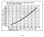
- Figs 4 and 5 indicate the chuck strength and flat crush strength of test cores as a function of the middle ply length/1000 mm. using a model structure, which has an inside diameter of 50 mm.
- the chuck strength tests have been conducted by a method in accordance with EP patent 309 123 (the vertical axis "Coretester strength" denotes the chuck strength).
- the inside diameter of the paperboard cores was selected to be 50 mm in order to be able to vary within the required ply width range by using a conventional spiral machine. The same effect is valid for other diameters as well, such as cores which have the inside diameter of 76 mm and 150 mm, which cores are commonly used for big paper rolls.
- Fig. 5 shows the influence of the middle ply length on the flat crush strength of the core, with the same core structure as in Fig. 4.
- Such cores as described in US 3,194,275 are typically used in handling of broad products, like e.g., fitted carpets, fabrics, plastics, or "scrims" used in excavation work for separating land masses from each other in road or yard bottoms.
- broad rug-type products do not support the core at all; on the contrary, they only strain it, especially as for beam strength.
- the applications of cores, according to US 3,194,275, used as discussed above do not involve chuck loading stresses. These products are reeled at very low speeds, typically about 10 to 75 m/min.
- US patent 3,194,275 suggests an approach in which a core constructed of plies in the length direction of the core, i.e., a convolutely wound tube, is replaced with a spirally wound tube, which, however, seeks to imitate a convolutely wound tube to the greatest possible extent. This is effected so that the material used is a paperboard ply which is orientated as much as possible in the machine direction (column 3, lines 4 to 14), and is then reeled into a spiral core so that it as much as possible resembles a convolutely wound tube. This is carried out by using the broadest possible average winding angle (as defined in the present invention, cf. Fig. 3. US patent 3,194,275 defines the average winding angle so that it corresponds to the complement of the average winding angle of the present invention).
- the present invention is also based on the discovery that because of dynamic loading present in real loading of paper industry cores, the most essential and the most important aspect in estimating the strength and expediency of such a paperboard core and other paperboard cores which are subject to heavy chuck loading, is not the flat crush strength but the chuck strength of the core.
- the flat crush strength of a core is usable to suggestively indicate chuck strength provided that the other factors, i.e., wall thickness, inside diameter, and the ply widths used are constant, i.e., the core structure is constant, and only the ply material is changing.
- the flat crush strength is, however, usually used as the main criterion when describing the expediency of a paperboard core, and it is roughly applicable to describing it, too.
- the arrangement according to the present invention provides an improvement in the strength of all cores for which the chuck strength is an important criterion of expediency.
- the average winding angle grows because the core diameter remains unchanged.
- the amount of gaps i.e., potential points of initial cracks per length unit in a linear metre of finished core is smaller.
- the capacity, chuck strength, and load-bearing capacity will increase. This makes it possible to reduce core manufacturing costs.
- the weakening effect of gaps on a core had to be compensated by stronger paperboard than what is needed for the arrangement of the present invention.
- an economic advantage is obtained also by a higher core production rate per time unit.
- the wall thickness of the paperboard core is comprised of paperboard plies, which have preferably been fabricated by using a press drying method, for example, a so-called Condebelt method.
Landscapes
- Paper (AREA)
- Storage Of Web-Like Or Filamentary Materials (AREA)
- Making Paper Articles (AREA)
- Machines For Manufacturing Corrugated Board In Mechanical Paper-Making Processes (AREA)
- Winding Of Webs (AREA)
- Mechanical Pencils And Projecting And Retracting Systems Therefor, And Multi-System Writing Instruments (AREA)
- Laminated Bodies (AREA)
- Radiation-Therapy Devices (AREA)
- Saccharide Compounds (AREA)
- Microscoopes, Condenser (AREA)
Abstract
Description
Table 1 shows a theoretical fabricating recipe of a prior art core of 13 mm x 150 mm,
- which has the inside diameter of 73 to 110 mm:
Lmp < 1550 mm, preferably less than 1450 mm, and more preferably less than 1300 mm, - which has the inside diameter of 111 to 144 mm:
Lmp < 1900 mm, preferably less than 1650 mm, and more preferably less than 1500 mm, and - which has the inside diameter of 145 to 180 mm:
Lmp < 2450 mm, preferably 2200 to 1500 mm, and more preferably less than 1500 mm,
Lmp is the web edge length of the paperboard ply on the cylindrical surface representing the z-direction stress maximum within the paperboard core wall, per 1 linear metre of the paperboard core.
Lmp < 4500 mm, preferably less than 3900 mm, and more preferably 3900 to 2000 mm, where
Lmp is the web edge length of the paperboard ply on the cylindrical surface representing the z-direction stress maximum within the wall of the paperboard core per 1 linear metre of the core.
with the inside diameter of the paperboard core being
- 73 mm to 110 mm,
at least 185 mm, preferably over 210 mm and more preferably over 230 mm,
with the inside diameter of the paperboard core being - 111 mm to 144 mm,
at least 205 mm, preferably over 210 mm. and more preferably over 230 mm,
with the inside diameter of the paperboard core being - 145 mm to 180 mm,
at least 210 mm, preferably over 250 mm, and more preferably 350 mm to 450mm, and
with the inside diameter of the paperboard core being - 181 mm to 310 mm,
at least 220 mm, preferably over 250 mm, and more preferably 350 mm to 500 mm, but
- which has the inside diameter of about 76 mm (3"):
Lmp < 1550 mm, preferably less than 1400 mm, and more preferably less than 1300 mm, and - which has the inside diameter of about 150 mm (6"):
Lmp < 2200 mm, preferably 2000 - 1500 mm, and more preferably less than 1500 mm,
- with the inside diameter of the paperboard core being about 76 mm (3") at least 185 mm, preferably over 210 mm, and more preferably 210 mm to 240 mm, and
- with the inside diameter of the paperboard core being about 150 mm (6") at least 230 mm, preferably over 250 mm, and more preferably 250 to 450 mm, but at most the maximum ply width Lmax of each core of a certain diameter, where Lmax = (π) x (core diameter in the specific point).
Claims (11)
- A method of fabricating spiral paperboard cores for the paper industry by winding paperboard plies spirally around a mandrel into a tube, the cores having a wall thickness H of 10 mm or more and an inside diameter over 70 mm, said cores being for use at winding/unwinding speeds of at least about 200 m/min (3.3 m/s), characterized in that on the cylindrical surface on which the maximal tensile and shear stress i.e. a z-direction stress maximum occur in the wall of a finished paperboard core, and in the vicinity of said cylindrical surface, including the paperboard ply in the middle of the core wall,Lmp is an edge length of the paperboard ply on the cylindrical surface per 1 linear metre of the paperboard core.with the inside diameter of the core being 73 mm to 110 mm:
Lmp < 1550 mm, preferably less than 1450 mm, and more preferably less than 1300 mm,with the inside diameter of the core being 111 mm to 144 mm:
Lmp < 1900 mm, preferably less than 1650 mm, and more preferably less than 1500 mm, andwith the inside diameter of the core being 145 mm to 180 mm,
Lmp < 2450 mm, preferably 2200 to 1500 mm, and more preferably less than 1500 mm, where - A method as recited in claim 1, characterized in that with the inside diameter of the core being 181 mm to 310 mm,
Lmp < 4500 mm, preferably less than 3900 mm, and more preferably 3900 to 2000 mm. - A method as recited in claim 1, characterized in that ply widths on the cylindrical surface representing the z-direction stress maximum in the wall of a finished paperboard core and in the vicinity of said cylindrical surface,
including the paperboard ply in the middle of the core wall, are,at most the maximum ply width Lmax of each core of a certain diameter, where Lmax = (π) x (x: diameter of the cylindrical surface).with the inside diameter of the paperboard core being 73 to 110 mm,
at least 185 mm, preferably over 210 mm, and more preferably over 230 mm,with the inside diameter of the paperboard core being 111 to 144 mm,
at least 205 mm, preferably over 210 mm, and more preferably over 230 mm, andwith the inside diameter of the paperboard core being 145 to 180 mm,
at least 210 mm, preferably over 250 mm, and more preferably 350 to 450 mm, but - A method as recited in claim 2, characterized in that ply widths on the cylindrical surface representing the z-direction stress maximum in the wall of a finished paperboard core, and in the vicinity of said cylindrical surface, including the paperboard ply in the middle of the core wall, are,with the inside diameter of the paperboard core being 181 to 310 mm,
at least 220 mm, preferably over 250 mm, and more preferably 350 to 500 mm, but
at most the maximum ply width Lmax of each core of a certain diameter, where Lmax = (π) x (x: diameter of the cylindrical surface). - A method as recited in claim 1, characterized in thatwith the inside diameter of the paperboard core being about 76 mm (3") :
Lmp < 1550 mm, preferably less than 1400 mm, and more preferably less than 1300 mm, andwith the inside diameter of the paperboard core being about 150 mm (6"):
Lmp < 2200 mm, preferably 2200 to 1500 mm, and more preferably less than 1500 mm. - A method as recited in claim 5, characterized in that ply widths on the cylindrical surface representing the z-direction stress maximum in the wall of a finished paperboard core, and in the vicinity of said cylindrical surface, including the paperboard ply in the middle of the wall, are,at most the maximum ply width Lmax of each core of a certain diameter, where Lmax = (π) x (x: diameter of the cylindrical surface).with the inside diameter of the paperboard core being about 76 mm (3"),
at least 185 mm, preferably over 210 mm, and more preferably 210 mm to 240 mm, andwith the inside diameter of the paperboard core being about 150 mm (6"),
at least 230 mm, preferably over 250 mm, and more preferably 250 mm to 450 mm, but - A spiral paperboard core for the paper industry or a spiral paperboard core intended for other purposes but requiring high chuck strength, comprising a plurality of paperboard plies wound spirally into a tube, the cores having a thickness H of 10 mm or more and an inside diameter over 70 mm, the cores being for use at winding/unwinding speeds of at least about 200 m/min (3.3 m/s), characterized in that on the cylindrical surface on which the maximal tensile and shear stresses i.e. z-direction stress maximum occur in the wall of the finished paperboard core, and in the vicinity of said cylindrical surface, including the paperboard ply in the middle of the core wallwith the inside diameter of the core being 73 mm to 110 mm:
Lmp < 1550 mm, preferably less than 1450 mm, and more preferably less than 1300 mm,with the inside diameter of the core being 111 mm to 144 mm:
Lmp < 1900 mm, preferably less than 1650 mm, and more preferably less than 1500 mm, andwith the inside diameter of the core being 145 mm to 180 mm,
Lmp < 2450 mm, preferably 2200 to 1500 mm, and more preferably less than 1500 mm, where
Lmp is an edge length of the paperboard ply on the cylindrical surface per 1 linear metre of the paperboard core. - A paperboard core for the paper industry as recited in claim 7, characterized in that on the cylindrical surface representing the z-direction stress maximum in the wall of a finished paperboard core, and in the vicinity of said cylindrical surface, including the paperboard plies in the middle of the core wall, the width of paperboard plies is preferably at least 200 mm, more preferably over 230 mm, but at most the maximum ply width Lmax of each core of a certain diameter, where Lmax = (π) x (x: diameter of the cylindrical surface), and preferably less than 550 mm.
- A paperboard core as recited in claim 7, characterized in that on the cylindrical surface representing the z-direction stress maximum in the wall of a finished paperboard core, and in the vicinity of said cylindrical surface, including the paperboard ply in the middle of the wall, the ply width is,at most the maximum ply width Lmax of each core of a certain diameter, where Lmax = (π) x (x: diameter of the cylindrical surface).with the inside diameter of the paperboard core being 73 mm to 110 mm,
at least 185 mm, preferably over 210 mm, and more preferably over 230 mm,with the inside diameter of the paperboard core being 111 mm to 144 mm,
at least 205 mm, preferably over 210 mm, and more preferably over 230 mm,with the inside diameter of the paperboard core being 145 mm to 180 mm,
at least 210 mm, preferably over 250 mm, and more preferably 350 mm to 450 mm, andwith the inside diameter of the paperboard core being 181 mm to 310 mm,
at least 220 mm, preferably over 250 mm, and more preferably 350 mm to 500 mm, but - A paperboard core as recited in any of claims 7 to 9, characterized in that at least a portion, preferably at least 1/5, of the wall thickness of the paperboard core is comprised of paperboard plies, which have been fabricated by using a press drying method, for example, a so-called Condebelt method.
- Use of a spiral paperboard core as recited in any of the claims 9 to 10 at winding/unwinding of paper rolls weighing at least 6.5 tons, preferably at least 8.5 tons.
Applications Claiming Priority (3)
| Application Number | Priority Date | Filing Date | Title |
|---|---|---|---|
| FI980145 | 1998-01-23 | ||
| FI980145A FI980145A7 (en) | 1998-01-23 | 1998-01-23 | Method for manufacturing paperboard cores with improved chucking resistance and paperboard core constructed in accordance with this method |
| PCT/FI1999/000043 WO1999039902A1 (en) | 1998-01-23 | 1999-01-22 | A paperboard core with an improved chuck strength, for the paper industry, and a method of fabricating such |
Publications (2)
| Publication Number | Publication Date |
|---|---|
| EP1071556A1 EP1071556A1 (en) | 2001-01-31 |
| EP1071556B1 true EP1071556B1 (en) | 2002-10-09 |
Family
ID=8550512
Family Applications (1)
| Application Number | Title | Priority Date | Filing Date |
|---|---|---|---|
| EP99901607A Expired - Lifetime EP1071556B1 (en) | 1998-01-23 | 1999-01-22 | A paperboard core with an improved chuck strength, for the paper industry, and a method of fabricating such |
Country Status (18)
| Country | Link |
|---|---|
| US (1) | US6540174B1 (en) |
| EP (1) | EP1071556B1 (en) |
| JP (1) | JP2002502725A (en) |
| KR (1) | KR20010034348A (en) |
| CN (1) | CN1112992C (en) |
| AT (1) | ATE225707T1 (en) |
| AU (1) | AU2165999A (en) |
| BR (1) | BR9907180A (en) |
| CA (1) | CA2316911C (en) |
| DE (2) | DE69903413T2 (en) |
| DK (1) | DK1071556T3 (en) |
| ES (1) | ES2183505T3 (en) |
| FI (1) | FI980145A7 (en) |
| FR (1) | FR2774022B3 (en) |
| IT (1) | IT247889Y1 (en) |
| PL (1) | PL188101B1 (en) |
| TW (1) | TW499526B (en) |
| WO (1) | WO1999039902A1 (en) |
Families Citing this family (6)
| Publication number | Priority date | Publication date | Assignee | Title |
|---|---|---|---|---|
| DE202004005645U1 (en) * | 2004-04-08 | 2004-06-09 | Koenig & Bauer Ag | Rolls of material and offset rotary press |
| US7204451B2 (en) * | 2004-02-25 | 2007-04-17 | Sonoco Development, Inc. | Winding core and associated method |
| US20060163420A1 (en) * | 2004-12-06 | 2006-07-27 | Sonoco Development, Inc. | High-stiffness winding core |
| US7712487B2 (en) * | 2006-09-13 | 2010-05-11 | Sonoco Development, Inc. | Spirally wound tube with voids and method for manufacturing the same |
| DE102010056339B4 (en) | 2010-12-18 | 2015-08-06 | Technische Universität Dresden | Stiffened hollow profile and method for producing stiffened hollow profiles and a winding module |
| US11370628B1 (en) * | 2021-10-15 | 2022-06-28 | Abzac Canada Inc. | Convolute cardboard tube, apparatus and method for manufacturing the same |
Family Cites Families (8)
| Publication number | Priority date | Publication date | Assignee | Title |
|---|---|---|---|---|
| US3194275A (en) | 1963-01-15 | 1965-07-13 | Sonoco Products Co | Spirally wound paper tube |
| FI80794C (en) | 1987-09-21 | 1990-07-10 | Ahlstroem Oy | ANORDINATION FOER TESTNING AV HYLSOR. |
| US5167994A (en) | 1991-04-19 | 1992-12-01 | Boise Cascade Corporation | Reusable core for paper rolls |
| US5505395A (en) | 1993-06-04 | 1996-04-09 | Sonoco Products Company | Multi-grade paperboard winding cores for yarns and films having enhanced resistance to inside diameter reduction |
| US5393582A (en) * | 1993-06-04 | 1995-02-28 | Sonoco Products Company | Enhanced crush strength construction multi-grade paperboard tubes |
| US5472154A (en) * | 1993-07-02 | 1995-12-05 | Sonoco Products Company | High spiral angle winding cores |
| US5379648A (en) | 1993-07-26 | 1995-01-10 | Sonoco Products Company | Method and apparatus for testing chew-out strength of paperboard core |
| CA2280947C (en) | 1997-02-14 | 2004-05-11 | Ahlstrom Alcore Oy | A structural ply of a paperboard core, a paperboard core made thereof, and a method of improving the stiffness of a paperboard core |
-
1998
- 1998-01-23 FI FI980145A patent/FI980145A7/en unknown
-
1999
- 1999-01-22 IT IT1999TO000007U patent/IT247889Y1/en active
- 1999-01-22 KR KR1020007008083A patent/KR20010034348A/en not_active Ceased
- 1999-01-22 US US09/582,994 patent/US6540174B1/en not_active Expired - Lifetime
- 1999-01-22 DE DE69903413T patent/DE69903413T2/en not_active Expired - Lifetime
- 1999-01-22 CN CN99802301A patent/CN1112992C/en not_active Expired - Fee Related
- 1999-01-22 PL PL99330987A patent/PL188101B1/en not_active IP Right Cessation
- 1999-01-22 AU AU21659/99A patent/AU2165999A/en not_active Abandoned
- 1999-01-22 CA CA002316911A patent/CA2316911C/en not_active Expired - Lifetime
- 1999-01-22 EP EP99901607A patent/EP1071556B1/en not_active Expired - Lifetime
- 1999-01-22 DE DE29901059U patent/DE29901059U1/en not_active Expired - Lifetime
- 1999-01-22 ES ES99901607T patent/ES2183505T3/en not_active Expired - Lifetime
- 1999-01-22 JP JP2000530364A patent/JP2002502725A/en active Pending
- 1999-01-22 AT AT99901607T patent/ATE225707T1/en active
- 1999-01-22 DK DK99901607T patent/DK1071556T3/en active
- 1999-01-22 WO PCT/FI1999/000043 patent/WO1999039902A1/en not_active Ceased
- 1999-01-22 FR FR9900720A patent/FR2774022B3/en not_active Expired - Lifetime
- 1999-01-22 BR BR9907180-0A patent/BR9907180A/en not_active IP Right Cessation
- 1999-01-23 TW TW088101094A patent/TW499526B/en not_active IP Right Cessation
Also Published As
| Publication number | Publication date |
|---|---|
| FR2774022A3 (en) | 1999-07-30 |
| CA2316911A1 (en) | 1999-08-12 |
| US6540174B1 (en) | 2003-04-01 |
| FI980145A7 (en) | 1999-07-24 |
| DE29901059U1 (en) | 1999-08-05 |
| EP1071556A1 (en) | 2001-01-31 |
| FI980145A0 (en) | 1998-01-23 |
| DK1071556T3 (en) | 2003-02-03 |
| BR9907180A (en) | 2000-10-10 |
| CN1288410A (en) | 2001-03-21 |
| DE69903413D1 (en) | 2002-11-14 |
| AU2165999A (en) | 1999-08-23 |
| WO1999039902A1 (en) | 1999-08-12 |
| CN1112992C (en) | 2003-07-02 |
| PL188101B1 (en) | 2004-12-31 |
| IT247889Y1 (en) | 2002-09-16 |
| FR2774022B3 (en) | 1999-12-24 |
| TW499526B (en) | 2002-08-21 |
| KR20010034348A (en) | 2001-04-25 |
| ATE225707T1 (en) | 2002-10-15 |
| DE69903413T2 (en) | 2003-06-26 |
| ES2183505T3 (en) | 2003-03-16 |
| CA2316911C (en) | 2005-06-28 |
| ITTO990007U1 (en) | 2000-07-22 |
| PL330987A1 (en) | 1999-08-02 |
| JP2002502725A (en) | 2002-01-29 |
Similar Documents
| Publication | Publication Date | Title |
|---|---|---|
| EP0740640B1 (en) | Yarn winding cores | |
| EP0627306B2 (en) | Enhanced crush strength construction multi-grade paperboard tubes | |
| US5582361A (en) | Support roller for paper-winding machine | |
| US5560566A (en) | Winder with elevated spool support rail | |
| US6540174B1 (en) | Paperboard core with an improved chuck strength, for the paper industry, and a method of fabricating such | |
| CA2233476C (en) | Centerwind assist for a paper winder system | |
| US6962736B1 (en) | Structural ply of a paperboard core, a paperboard core made thereof, and a method of improving the stiffness of a paperboard core | |
| FI129063B (en) | Method of controlling caliper of the fiber web of a parent roll and production line for producing fiber webs | |
| EP3018082A1 (en) | Slitter-winder for winding of pulp webs | |
| US6671958B2 (en) | Method for producing a roll for a paper/boardmaking machine | |
| JP5032845B2 (en) | Winding method for paper, paperboard or raw web and winder for paper, paperboard or raw web | |
| US20060113422A1 (en) | Winder | |
| FI20206035A1 (en) | Method of controlling caliper of the fiber web of a parent roll and production line for producing fiber webs | |
| Tuomisto et al. | Eliminating production losses on a paper machine reel | |
| TH33651A (en) | Structure layer of cardboard core tube The cardboard core tubes are made with these structural layers. And how to improve the strength of cardboard core tubes |
Legal Events
| Date | Code | Title | Description |
|---|---|---|---|
| PUAI | Public reference made under article 153(3) epc to a published international application that has entered the european phase |
Free format text: ORIGINAL CODE: 0009012 |
|
| 17P | Request for examination filed |
Effective date: 20000712 |
|
| AK | Designated contracting states |
Kind code of ref document: A1 Designated state(s): AT BE CH DE DK ES FI FR GB GR IT LI LU NL PT SE |
|
| 17Q | First examination report despatched |
Effective date: 20010202 |
|
| GRAG | Despatch of communication of intention to grant |
Free format text: ORIGINAL CODE: EPIDOS AGRA |
|
| RAP1 | Party data changed (applicant data changed or rights of an application transferred) |
Owner name: AHLSTROEM CORES OY |
|
| GRAG | Despatch of communication of intention to grant |
Free format text: ORIGINAL CODE: EPIDOS AGRA |
|
| GRAG | Despatch of communication of intention to grant |
Free format text: ORIGINAL CODE: EPIDOS AGRA |
|
| GRAH | Despatch of communication of intention to grant a patent |
Free format text: ORIGINAL CODE: EPIDOS IGRA |
|
| GRAH | Despatch of communication of intention to grant a patent |
Free format text: ORIGINAL CODE: EPIDOS IGRA |
|
| GRAA | (expected) grant |
Free format text: ORIGINAL CODE: 0009210 |
|
| AK | Designated contracting states |
Kind code of ref document: B1 Designated state(s): AT BE CH DE DK ES FI FR GB GR IT LI LU NL PT SE |
|
| PG25 | Lapsed in a contracting state [announced via postgrant information from national office to epo] |
Ref country code: GR Free format text: LAPSE BECAUSE OF FAILURE TO SUBMIT A TRANSLATION OF THE DESCRIPTION OR TO PAY THE FEE WITHIN THE PRESCRIBED TIME-LIMIT Effective date: 20021009 |
|
| REF | Corresponds to: |
Ref document number: 225707 Country of ref document: AT Date of ref document: 20021015 Kind code of ref document: T |
|
| REG | Reference to a national code |
Ref country code: GB Ref legal event code: FG4D |
|
| REG | Reference to a national code |
Ref country code: CH Ref legal event code: EP |
|
| REG | Reference to a national code |
Ref country code: CH Ref legal event code: NV Representative=s name: BOVARD AG PATENTANWAELTE |
|
| REF | Corresponds to: |
Ref document number: 69903413 Country of ref document: DE Date of ref document: 20021114 |
|
| PG25 | Lapsed in a contracting state [announced via postgrant information from national office to epo] |
Ref country code: PT Free format text: LAPSE BECAUSE OF FAILURE TO SUBMIT A TRANSLATION OF THE DESCRIPTION OR TO PAY THE FEE WITHIN THE PRESCRIBED TIME-LIMIT Effective date: 20030109 |
|
| ET | Fr: translation filed | ||
| REG | Reference to a national code |
Ref country code: DK Ref legal event code: T3 |
|
| REG | Reference to a national code |
Ref country code: ES Ref legal event code: FG2A Ref document number: 2183505 Country of ref document: ES Kind code of ref document: T3 |
|
| PLBQ | Unpublished change to opponent data |
Free format text: ORIGINAL CODE: EPIDOS OPPO |
|
| PLBI | Opposition filed |
Free format text: ORIGINAL CODE: 0009260 |
|
| PLAX | Notice of opposition and request to file observation + time limit sent |
Free format text: ORIGINAL CODE: EPIDOSNOBS2 |
|
| 26 | Opposition filed |
Opponent name: PAUL &CO., INHABER K. KUNERT & SOEHNE GMBH Effective date: 20030709 Opponent name: CORENSO ELFES GMBH & CO. KG Effective date: 20030709 |
|
| NLR1 | Nl: opposition has been filed with the epo |
Opponent name: PAUL &CO., INHABER K. KUNERT & SOEHNE GMBH & CO. Opponent name: CORENSO ELFES GMBH & CO. KG |
|
| PLAX | Notice of opposition and request to file observation + time limit sent |
Free format text: ORIGINAL CODE: EPIDOSNOBS2 |
|
| PLAX | Notice of opposition and request to file observation + time limit sent |
Free format text: ORIGINAL CODE: EPIDOSNOBS2 |
|
| PLAX | Notice of opposition and request to file observation + time limit sent |
Free format text: ORIGINAL CODE: EPIDOSNOBS2 |
|
| PLBB | Reply of patent proprietor to notice(s) of opposition received |
Free format text: ORIGINAL CODE: EPIDOSNOBS3 |
|
| PG25 | Lapsed in a contracting state [announced via postgrant information from national office to epo] |
Ref country code: IT Free format text: LAPSE BECAUSE OF NON-PAYMENT OF DUE FEES Effective date: 20050122 |
|
| PLAY | Examination report in opposition despatched + time limit |
Free format text: ORIGINAL CODE: EPIDOSNORE2 |
|
| PLAQ | Examination of admissibility of opposition: information related to despatch of communication + time limit deleted |
Free format text: ORIGINAL CODE: EPIDOSDOPE2 |
|
| PLAR | Examination of admissibility of opposition: information related to receipt of reply deleted |
Free format text: ORIGINAL CODE: EPIDOSDOPE4 |
|
| PLBQ | Unpublished change to opponent data |
Free format text: ORIGINAL CODE: EPIDOS OPPO |
|
| PLAB | Opposition data, opponent's data or that of the opponent's representative modified |
Free format text: ORIGINAL CODE: 0009299OPPO |
|
| R26 | Opposition filed (corrected) |
Opponent name: PAUL & CO GMBH & CO KG Effective date: 20030709 Opponent name: CORENSO ELFES GMBH & CO. KG Effective date: 20030709 |
|
| NLR1 | Nl: opposition has been filed with the epo |
Opponent name: PAUL & CO GMBH & CO KG Opponent name: CORENSO ELFES GMBH & CO. KG |
|
| PLAH | Information related to despatch of examination report in opposition + time limit modified |
Free format text: ORIGINAL CODE: EPIDOSCORE2 |
|
| PLAH | Information related to despatch of examination report in opposition + time limit modified |
Free format text: ORIGINAL CODE: EPIDOSCORE2 |
|
| PLBC | Reply to examination report in opposition received |
Free format text: ORIGINAL CODE: EPIDOSNORE3 |
|
| RAP2 | Party data changed (patent owner data changed or rights of a patent transferred) |
Owner name: SONOCO-ALCORE OY |
|
| NLT2 | Nl: modifications (of names), taken from the european patent patent bulletin |
Owner name: SONOCO-ALCORE OY Effective date: 20060322 |
|
| PLAB | Opposition data, opponent's data or that of the opponent's representative modified |
Free format text: ORIGINAL CODE: 0009299OPPO |
|
| PLCK | Communication despatched that opposition was rejected |
Free format text: ORIGINAL CODE: EPIDOSNREJ1 |
|
| PLAG | Information modified related to despatch of communication that opposition is rejected |
Free format text: ORIGINAL CODE: EPIDOSCREJ1 |
|
| PGRI | Patent reinstated in contracting state [announced from national office to epo] |
Ref country code: IT Effective date: 20090101 |
|
| APBM | Appeal reference recorded |
Free format text: ORIGINAL CODE: EPIDOSNREFNO |
|
| APBP | Date of receipt of notice of appeal recorded |
Free format text: ORIGINAL CODE: EPIDOSNNOA2O |
|
| APAH | Appeal reference modified |
Free format text: ORIGINAL CODE: EPIDOSCREFNO |
|
| PLAO | Information deleted related to despatch of communication that opposition is rejected |
Free format text: ORIGINAL CODE: EPIDOSDREJ1 |
|
| PLCK | Communication despatched that opposition was rejected |
Free format text: ORIGINAL CODE: EPIDOSNREJ1 |
|
| APBQ | Date of receipt of statement of grounds of appeal recorded |
Free format text: ORIGINAL CODE: EPIDOSNNOA3O |
|
| PLAB | Opposition data, opponent's data or that of the opponent's representative modified |
Free format text: ORIGINAL CODE: 0009299OPPO |
|
| R26 | Opposition filed (corrected) |
Opponent name: PAUL & CO GMBH & CO KG Effective date: 20030709 Opponent name: CORENSO ELFES GMBH & CO. KG Effective date: 20030709 |
|
| NLR1 | Nl: opposition has been filed with the epo |
Opponent name: PAUL & CO GMBH & CO KG Opponent name: CORENSO ELFES GMBH & CO. KG |
|
| APBU | Appeal procedure closed |
Free format text: ORIGINAL CODE: EPIDOSNNOA9O |
|
| PLBN | Opposition rejected |
Free format text: ORIGINAL CODE: 0009273 |
|
| STAA | Information on the status of an ep patent application or granted ep patent |
Free format text: STATUS: OPPOSITION REJECTED |
|
| 27O | Opposition rejected |
Effective date: 20090928 |
|
| NLR2 | Nl: decision of opposition |
Effective date: 20090928 |
|
| REG | Reference to a national code |
Ref country code: CH Ref legal event code: PFA Owner name: AHLSTROM CORES OY Free format text: AHLSTROM CORES OY#PL 100#48601 KARHULA (FI) -TRANSFER TO- AHLSTROM CORES OY#PL 100#48601 KARHULA (FI) |
|
| REG | Reference to a national code |
Ref country code: DE Ref legal event code: R409 Ref document number: 69903413 Country of ref document: DE Ref country code: DE Ref legal event code: R097 Ref document number: 69903413 Country of ref document: DE Ref country code: DE Ref legal event code: R042 Ref document number: 69903413 Country of ref document: DE Ref country code: DE Ref legal event code: R040 Ref document number: 69903413 Country of ref document: DE |
|
| REG | Reference to a national code |
Ref country code: DE Ref legal event code: R042 Ref document number: 69903413 Country of ref document: DE Effective date: 20140612 |
|
| PG25 | Lapsed in a contracting state [announced via postgrant information from national office to epo] |
Ref country code: DE Free format text: THE PATENT HAS BEEN ANNULLED BY A DECISION OF A NATIONAL AUTHORITY Effective date: 20140612 |
|
| PGFP | Annual fee paid to national office [announced via postgrant information from national office to epo] |
Ref country code: DK Payment date: 20150112 Year of fee payment: 17 |
|
| REG | Reference to a national code |
Ref country code: DE Ref legal event code: R409 Ref document number: 69903413 Country of ref document: DE |
|
| PGRI | Patent reinstated in contracting state [announced from national office to epo] |
Ref country code: DE Effective date: 20150708 |
|
| REG | Reference to a national code |
Ref country code: FR Ref legal event code: PLFP Year of fee payment: 18 |
|
| REG | Reference to a national code |
Ref country code: DK Ref legal event code: EBP Effective date: 20160131 |
|
| REG | Reference to a national code |
Ref country code: FR Ref legal event code: PLFP Year of fee payment: 19 |
|
| PG25 | Lapsed in a contracting state [announced via postgrant information from national office to epo] |
Ref country code: DK Free format text: LAPSE BECAUSE OF NON-PAYMENT OF DUE FEES Effective date: 20160131 |
|
| REG | Reference to a national code |
Ref country code: FR Ref legal event code: PLFP Year of fee payment: 20 |
|
| PGFP | Annual fee paid to national office [announced via postgrant information from national office to epo] |
Ref country code: FR Payment date: 20171220 Year of fee payment: 20 Ref country code: FI Payment date: 20171228 Year of fee payment: 20 |
|
| PGFP | Annual fee paid to national office [announced via postgrant information from national office to epo] |
Ref country code: GB Payment date: 20171228 Year of fee payment: 20 Ref country code: LU Payment date: 20180108 Year of fee payment: 20 |
|
| PGFP | Annual fee paid to national office [announced via postgrant information from national office to epo] |
Ref country code: NL Payment date: 20180111 Year of fee payment: 20 |
|
| PGFP | Annual fee paid to national office [announced via postgrant information from national office to epo] |
Ref country code: DE Payment date: 20180109 Year of fee payment: 20 Ref country code: CH Payment date: 20180125 Year of fee payment: 20 Ref country code: ES Payment date: 20180202 Year of fee payment: 20 |
|
| PGFP | Annual fee paid to national office [announced via postgrant information from national office to epo] |
Ref country code: AT Payment date: 20171228 Year of fee payment: 20 Ref country code: IT Payment date: 20180110 Year of fee payment: 20 Ref country code: BE Payment date: 20180118 Year of fee payment: 20 Ref country code: SE Payment date: 20180109 Year of fee payment: 20 |
|
| REG | Reference to a national code |
Ref country code: DE Ref legal event code: R071 Ref document number: 69903413 Country of ref document: DE |
|
| REG | Reference to a national code |
Ref country code: NL Ref legal event code: MK Effective date: 20190121 |
|
| REG | Reference to a national code |
Ref country code: CH Ref legal event code: PL |
|
| REG | Reference to a national code |
Ref country code: GB Ref legal event code: PE20 Expiry date: 20190121 |
|
| REG | Reference to a national code |
Ref country code: BE Ref legal event code: MK Effective date: 20190122 |
|
| REG | Reference to a national code |
Ref country code: AT Ref legal event code: MK07 Ref document number: 225707 Country of ref document: AT Kind code of ref document: T Effective date: 20190122 |
|
| PG25 | Lapsed in a contracting state [announced via postgrant information from national office to epo] |
Ref country code: GB Free format text: LAPSE BECAUSE OF EXPIRATION OF PROTECTION Effective date: 20190121 |
|
| REG | Reference to a national code |
Ref country code: ES Ref legal event code: FD2A Effective date: 20220104 |
|
| PG25 | Lapsed in a contracting state [announced via postgrant information from national office to epo] |
Ref country code: ES Free format text: LAPSE BECAUSE OF EXPIRATION OF PROTECTION Effective date: 20190123 |