EP1071182A1 - Boítier d'isolation pour appareil à rapporter sur le socle d'une goulotte par l'intermédiaire d'un support - Google Patents
Boítier d'isolation pour appareil à rapporter sur le socle d'une goulotte par l'intermédiaire d'un support Download PDFInfo
- Publication number
- EP1071182A1 EP1071182A1 EP00401623A EP00401623A EP1071182A1 EP 1071182 A1 EP1071182 A1 EP 1071182A1 EP 00401623 A EP00401623 A EP 00401623A EP 00401623 A EP00401623 A EP 00401623A EP 1071182 A1 EP1071182 A1 EP 1071182A1
- Authority
- EP
- European Patent Office
- Prior art keywords
- covering
- housing according
- insulation housing
- side wall
- support
- Prior art date
- Legal status (The legal status is an assumption and is not a legal conclusion. Google has not performed a legal analysis and makes no representation as to the accuracy of the status listed.)
- Granted
Links
- 239000000725 suspension Substances 0.000 claims abstract description 12
- 238000009413 insulation Methods 0.000 claims description 54
- 230000008878 coupling Effects 0.000 claims description 19
- 238000010168 coupling process Methods 0.000 claims description 19
- 238000005859 coupling reaction Methods 0.000 claims description 19
- 230000008030 elimination Effects 0.000 claims description 4
- 238000003379 elimination reaction Methods 0.000 claims description 4
- 238000002955 isolation Methods 0.000 abstract description 7
- 239000004020 conductor Substances 0.000 description 6
- 238000005253 cladding Methods 0.000 description 2
- 230000000295 complement effect Effects 0.000 description 2
- 238000000465 moulding Methods 0.000 description 2
- 230000014759 maintenance of location Effects 0.000 description 1
- 238000004519 manufacturing process Methods 0.000 description 1
- 230000000717 retained effect Effects 0.000 description 1
- 229920002994 synthetic fiber Polymers 0.000 description 1
- 210000002105 tongue Anatomy 0.000 description 1
Images



Classifications
-
- H—ELECTRICITY
- H02—GENERATION; CONVERSION OR DISTRIBUTION OF ELECTRIC POWER
- H02G—INSTALLATION OF ELECTRIC CABLES OR LINES, OR OF COMBINED OPTICAL AND ELECTRIC CABLES OR LINES
- H02G3/00—Installations of electric cables or lines or protective tubing therefor in or on buildings, equivalent structures or vehicles
- H02G3/02—Details
- H02G3/08—Distribution boxes; Connection or junction boxes
- H02G3/12—Distribution boxes; Connection or junction boxes for flush mounting
- H02G3/128—Distribution boxes; Connection or junction boxes for flush mounting in plinths, channels, raceways or similar
Definitions
- the present invention relates generally to the equipment of chutes of the type used, for example for the support, the housing and protection of various devices, and in particular of various electrical appliances, as well as for housing and protecting cables, conductors or other conduits necessary to serve these appliances.
- the term “trunking” is used here to designate a profile formed of a on the one hand, a base, the cross section of which is open, and, on the other hand, a cover, which is attached, in practice by snap-fastening, on this base, for the closing of it.
- the present invention relates more particularly to the case where, for its subject to such a chute, a device is attached to the base of the latter by means of a support itself attached to this base.
- the present invention relates to the housing of insulation which is then customary to have around the device, away from the latter, to ensure all the desirable protection against direct access to active parts of such an apparatus when the chute cover is removed, which is the case, for example, if one or more cables or conductors additional are to be installed.
- this insulation box is fixed on the bottom of the base of the chute.
- the first is that, when the insulation box thus extends to count from the bottom of the base, the only space left free in it for the passage of cables or conductors required is reduced to that possibly still remaining laterally on either side of this housing of insulation, which can cause difficulties when this case of insulation has a relatively large width and / or when the the chute itself has a relatively small width.
- the second problem is that the insulation box must itself be adapted in height to the height of the chute.
- an insulation box comprising, on the one hand, suspension means, by which it is capable of being coupled to such a support, and, on the other hand, a covering, by which it is able to surround at a distance the device attached to this support, this covering comprising in practice generally a bottom and a side wall and thus being generally in the form of bowl.
- such an insulation box advantageously allows the passage of cables or conductors between it and this background.
- such an insulation box may be suitable for a trunking given height and / or for a well-defined type of support, there is no is not necessarily the case for chutes of different heights and / or for supports of different types.
- the insulation box suspended from this support can, as before, decrease in a very unfavorable way the useful internal volume left free for the passage of cables or conductors between him and the bottom of the base.
- the present invention generally relates to a provision making it possible to minimize, if not cancel, this drawback.
- an insulation box for device to be attached to the base of a chute via a support of the kind comprising, on the one hand, means of suspension, by which it is capable of being coupled to such a support, and, on the other hand, a covering, by which it is able to remotely surround the device attached to this support, this covering comprising, on at least part of its periphery, a side wall
- this insulation box being generally characterized in that its suspension means are lines fitted with coupling means to the minus two different levels, and in that, jointly, on a part at less of its periphery, the upper portion, at least, of the side wall of its cover is retractable.
- the suspension height of the insulation box according to the invention in the chute can be adjusted to best suit the height thereof and / or depending on the type of support attached to the base from this chute.
- the arrangement according to the invention allows advantageously to best adapt the volume of this insulation box to the general configuration of the assembly, and, thus, to minimize at best its impact on the useful internal volume of the chute, thus leaving in it all the space necessary for the passage of cables or conductors required.
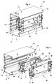
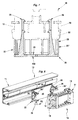
- the chute 10 to be equipped has a base 11 whose cross section is open.
- this cross section is generally rectangular, the base 11 comprising, on the one hand, a bottom 12, by which it is adapted to be applied to any wall, not shown, and, on the other hand, two lateral wings 13, which extend substantially perpendicular to the bottom 12, and which both have the same height.
- the base 11 has two returns 14, which, each coming respectively from these two lateral wings 13, the along the free edge of these, extend towards one another, parallel to the bottom 12, defining with each other its outlet 15.
- the chute 10 is completed by a cover, not shown, suitable for being attached to the base 11 for closing thereof.
- this cover then extends from one to the other of the returns 14, and, for its retention, these each form, along their free edge, a snap gutter 17.
- a support 18 is used, which is suitable for receiving a such device, and which is itself adapted to be attached to the base 11.
- This support 18 is also well known by itself, and does not fall under not specific to the present invention, it will not be described in detail either here.
- the support 18 is reduced to a frame, and it intervenes entirely at level with the returns 14 of the base 11, without making protruding on it.
- an insulation box 20 comprising, on the one hand, according to arrangements described in more detail subsequently, suspension means 21, by which it is able to be coupled to such a support 18, and, on the other hand, a covering 22, by which it is able to surround the device attached to this support 18, this covering from a distance 22 itself comprising, for this purpose, over at least part of its periphery, a side wall 25.
- the suspension means 21 of the insulation box 20 are lines 26 provided with coupling means 27 to at least two different levels, and jointly on at least part of the perimeter of this insulation box 20, the upper portion 25 ', at least, of the wall lateral 25 of its covering 22 is retractable.
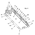
- the side wall 25 of the covering 22 extends over all, or almost all, of its periphery, and, in addition to this side wall 25, this covering 22 includes a bottom 29.
- the side wall 25 has, in plan, an outline generally rectangular, comprising, on the one hand, two panels transverse 25A, and, on the other hand, alternately with these two panels transverse 25A, two longitudinal panels 25B.
- the middle part 30 of the transverse panels 25A is recessed inward relative to their end portion 31, while being parallel thereto.
- the lines 26 come from from the bottom 29 of the covering 22, and they participate in the constitution of the wall lateral 25 thereof.
- these lines 26 intervene between the part median 30 of the transverse panels 25A of this side wall 25 and the end parts 31 of these transverse panels 25A.
- these lines 26 are in the form of tongues, which, in width, extend substantially parallel to the longitudinal panels 25B of the side wall 25 of the covering 22, and, therefore, substantially perpendicular both to the middle part 30 of the panels transverse 25A of this side wall 25 than the end portions 31 of these transverse panels 25A, and the height of which, from the bottom 29 of the covering 22 is greater than that of the side wall 25.
- the lines 26 are isolated from the rest of the side wall 25 of the covering 22 by slots 32 which run over their entire height from the bottom 29 of this covering 22.
- each hanger 26 there is thus, on one side, a slot 32 which isolates it of the middle part 30 of the corresponding transverse panel 25A of the wall side 25, and a slot 32 which isolates it from the end portion 31 corresponding to this transverse panel 25A.
- the coupling means 27 of which have the lines 26 are simple notches that extend parallel to the bottom 29 of the covering 22.
- these coupling means 27 protrude on that of the faces of the lines 26 which faces inward, and they extend parallel to the longitudinal panels 25B of the side part 25 of the covering 22.
- the lines 26 include, each, at least two sections 26 ', 26 ", namely an upper section 26' and a lower section 26 ", which, for the presence of coupling means 27 to two different levels, are each fitted with such coupling means 27, and which are separated from each other by a zone of least resistance 33 specific to allow the elimination of the section 26 ′, 26 "furthest from the bottom 29 of the covering 22, in this case the upper section 26 '.
- the zone of least resistance 33 extends parallel to the bottom 29 of the covering 22.
- these coupling means 35 are simple notches formed by the edge of openings 36 which, provided for this purpose on the support 18, in correspondence with the lines 26 of the insulation box 20, allow these lines 26 to engage on this support 18.
- the coupling means 27 extend flush with the free end of this upper section 26 '.
- the coupling means 27 extend flush with the corresponding zone of least resistance 33.
- the coupling means 27 of the lower section 26 "of the lines 26 extend in practice substantially to level with the free edge of the side wall 25 of the covering 22, while being slightly above this free edge.
- the lower section 26 "of the lines 26 is also stiffened by a rib 38, which extends over at least part of its height from the bottom 29 of the cladding 22, the side opposite to the coupling means 27.
- the side wall 25 of the covering 22 is retractable over its entire height.
- the side wall 25 of the covering 22 is, to do this, subdivided, in the embodiment shown, into at least two 25 ', 25 "portions, with, at the base of each of these 25', 25" portions, a zone of least resistance 39 capable of allowing the elimination of the or overlying 25 ', 25 "portions.
- the zone of least resistance 39 results, in practice, from a groove 40 which recesses the outside face side wall 25.
- this groove 40 runs flush with the bottom 29.
- the side wall 25 of the cladding 22 is, in the embodiment shown, divided into sides 41 by slots 42 which extend in practice perpendicular to the background 29.
- the bottom 29 of the covering 22 comprises, at least locally, in the embodiment shown, beyond the side wall 25 of this covering 22, a extension 44, and this extension 44 is at least partially retractable.
- this extension 44 of the bottom 29 comprises, on the one hand, two transverse panels 44A, which extend to the right of the middle part 30 of the transverse panels 25A of this wall lateral 25, between the end portions 31 of these transverse panels 25A, and, on the other hand, longitudinal panels 44B, which extend along longitudinal panels 25B of this side wall 25.
- the extension 44 of the bottom 29 of the covering 22 is retractable over its entire extension, that is to say both with regard to its transverse panels 44A only with regard to its longitudinal panels 44B.
- the transverse panels 44A have a thickness substantially equal to that of the bottom 29, and, to be retractable, they are separated from it by slots 45, which, established from place in place, along their root, affect their entire thickness.
- the longitudinal panels 44B have a thickness much lower than that of the bottom 29, which is enough to make them retractable.
- the extension 44 of the bottom 29 of this covering 22 is, in the embodiment shown, split into sections 46 by slots 47.
- these slots 47 are each established respectively in correspondence with the slots 42 dividing into sections 41 the longitudinal panels 25B of the side wall 25.
- the panels transverse 25A of the side wall 25 of the covering 22 are themselves separated from the longitudinal panels 25B of this side wall 25 by slots 48 which run over the entire height of this side wall 25, in the corner areas thereof.
- the wall lateral 25 of the covering 22 is preserved in its integrity, and so are even lines 26.
- the support 18 is still of a different type.
- this is an enhanced support 18, that is to say a support 18 having, above its groove means 19, a superstructure 51 by which it is intended to protrude at least in part on the base 11, when, as in the present case, the height, or depth, of the latter is relatively small.
- FIG. 10 is similar to that illustrated in FIGS. 8 and 9, but for which the base 11 is assumed to have a greater width.
- the longitudinal panels 44B of the extension 44 of the bottom 29 of the covering 22 are advantageously preserved, to meet desirable insulation.
- the insulation box 20 according to the invention can advantageously be made in one piece, by molding a any synthetic material.
Landscapes
- Engineering & Computer Science (AREA)
- Architecture (AREA)
- Civil Engineering (AREA)
- Structural Engineering (AREA)
- Casings For Electric Apparatus (AREA)
- Details Of Indoor Wiring (AREA)
- Insulating Bodies (AREA)
- Connector Housings Or Holding Contact Members (AREA)
Abstract
Description
Claims (16)
- Boítier d'isolation pour appareil à rapporter sur le socle (11) d'une goulotte (10) par l'intermédiaire d'un support (18), du genre comportant, d'une part, des moyens de suspension (21), par lesquels il est apte à être attelé à un tel support (18), et, d'autre part, un habillage (22), par lequel il est apte à entourer à distance l'appareil rapporté sur ce support (18), cet habillage (22) comportant, sur une partie au moins de son pourtour, une paroi latérale (25), caractérisé en ce que ses moyens de suspension (21) sont des suspentes (26) munies de moyens d'attelage (27) à au moins deux niveaux différents, et en ce que, conjointement, sur une partie au moins de son pourtour, la portion supérieure (25'), au moins, de la paroi latérale (25) de son habillage (22) est escamotable.
- Boítier d'isolation suivant la revendication 1, caractérisé en ce que, à compter de leur extrémité libre, les suspentes (26) comportent au moins deux tronçons (26', 26"), qui, pour la présence de moyens d'attelage (27) à deux niveaux différents, sont chacun équipés de tels moyens d'attelage (27), et qui sont séparés l'un de l'autre par une zone de moindre résistance (33) propre à permettre l'élimination du tronçon (26') le plus éloigné du fond (29) de l'habillage (22).
- Boítier d'isolation suivant la revendication 2, caractérisé en ce que, pour l'un et l'autre des deux tronçons (26', 26") des suspentes (26), les moyens d'attelage (27) sont de même type.
- Boítier d'isolation suivant l'une quelconque des revendications 1 à 3, caractérisé en ce que, l'habillage (22) comportant un fond (29), les suspentes (26) sont issues de ce fond (29).
- Boítier d'isolation suivant la revendication 4, caractérisé en ce que les suspentes (26) participent à la constitution de la paroi latérale (25) de l'habillage (22).
- Boítier d'isolation suivant la revendication 5, caractérisé en ce que les suspentes (26) sont isolées du reste de la paroi latérale (25) de l'habillage (22) par des fentes (32) qui courent sur toute leur hauteur.
- Boítier d'isolation suivant l'une quelconque des revendications 1 à 6, caractérisé en ce que la paroi latérale (25) de l'habillage (22) a, en plan, un contour globalement rectangulaire, en comportant deux panneaux transversaux (25A), et, en alternance avec ces deux panneaux transversaux (25A), deux panneaux longitudinaux (25B), et la partie médiane (30) des panneaux transversaux (25A) est en retrait par rapport à leur partie d'extrémité (31).
- Boítier d'isolation suivant les revendications 5 et 7, prises conjointement, caractérisé en ce que les suspentes (26) interviennent entre la partie médiane (30) des panneaux transversaux (25A) de la paroi latérale (25) de l'habillage (22) et les parties d'extrémité (31) de ces panneaux transversaux (25A).
- Boítier d'isolation suivant l'une quelconque des revendications 1 à 8, caractérisé en ce que la paroi latérale (25) de l'habillage (22) est escamotable sur toute sa hauteur.
- Boítier d'isolation suivant la revendication 9, caractérisé en ce que, à compter de son bord libre, la paroi latérale (25) de l'habillage (22) est subdivisée en au moins deux portions (25', 25"), avec, à la base de chacune de ces portions (25', 25"), une zone de moindre résistance (39) propre à permettre l'élimination de la ou des portions (25', 25") sus-jacentes.
- Boítier d'isolation suivant l'une quelconque des revendications 1 à 10, caractérisé en ce que, le long de son pourtour, la paroi latérale (25) de l'habillage (22) est fractionnée en pans (41) par des fentes (42).
- Boítier d'isolation suivant l'une quelconque des revendications 1 à 11, caractérisé en ce que, sur une partie au moins de son pourtour, le fond (29) de l'habillage (22) comporte, au moins localement, au-delà de la paroi latérale (25) de cet habillage (22), un prolongement (44).
- Boítier d'isolation suivant la revendication 12, caractérisé en ce que le prolongement (44) du fond (29) de l'habillage (22) est au moins en partie escamotable.
- Boítier d'isolation suivant la revendication 13, caractérisé en ce que le prolongement (44) du fond (29) de l'habillage (22) est escamotable sur toute son extension.
- Boítier d'isolation suivant l'une quelconque des revendications 12 à 14, caractérisé en ce que le prolongement (44) du fond (29) de l'habillage (22) est fractionné en pans (46) par des fentes (47).
- Boítier d'isolation suivant les revendications 19 et 15, prises conjointement, caractérisé en ce que les fentes (47) sont établies en correspondance avec les fentes (42).
Applications Claiming Priority (2)
| Application Number | Priority Date | Filing Date | Title |
|---|---|---|---|
| FR9909400 | 1999-07-20 | ||
| FR9909400A FR2796771B1 (fr) | 1999-07-20 | 1999-07-20 | Boitier d'isolation pour appareil a rapporter sur le socle d'une goulotte par l'intermediaire d'un support |
Publications (2)
| Publication Number | Publication Date |
|---|---|
| EP1071182A1 true EP1071182A1 (fr) | 2001-01-24 |
| EP1071182B1 EP1071182B1 (fr) | 2010-08-11 |
Family
ID=9548307
Family Applications (1)
| Application Number | Title | Priority Date | Filing Date |
|---|---|---|---|
| EP00401623A Expired - Lifetime EP1071182B1 (fr) | 1999-07-20 | 2000-06-08 | Boîtier d'isolation pour appareil à rapporter sur le socle d'une goulotte par l'intermédiaire d'un support |
Country Status (10)
| Country | Link |
|---|---|
| US (1) | US6384327B1 (fr) |
| EP (1) | EP1071182B1 (fr) |
| BR (1) | BR0003446A (fr) |
| DE (1) | DE60044796D1 (fr) |
| ES (1) | ES2350474T3 (fr) |
| FR (1) | FR2796771B1 (fr) |
| HU (1) | HU223783B1 (fr) |
| PL (1) | PL341133A1 (fr) |
| RU (1) | RU2253173C2 (fr) |
| TR (1) | TR200002153A2 (fr) |
Cited By (2)
| Publication number | Priority date | Publication date | Assignee | Title |
|---|---|---|---|---|
| EP2149952A1 (fr) | 2008-07-28 | 2010-02-03 | Unex Aparellaje Electrico S.L. | Support pour pluriel mécanismes électrique |
| FR2986669A1 (fr) * | 2012-02-03 | 2013-08-09 | Legrand France | Support multi-appareillages de boitier electrique multipostes |
Families Citing this family (7)
| Publication number | Priority date | Publication date | Assignee | Title |
|---|---|---|---|---|
| WO2002015354A1 (fr) * | 2000-08-18 | 2002-02-21 | Technigroup Far East Pte Ltd. | Boitier permettant l'agencement des fils electriques et des fils de transmission de donnees |
| FR2833772B1 (fr) * | 2001-12-14 | 2004-07-30 | Planet Wattohm Sa | Accessoire d'immobilisation d'un appareillage electrique a clipsage direct dans un socle de goulotte |
| US6867373B2 (en) * | 2002-06-14 | 2005-03-15 | Square D Company | Sprinkler resistant tap-off base assembly |
| US6881083B2 (en) * | 2002-07-19 | 2005-04-19 | The Wiremold Company | Raceway system with selectively placed outlet devices |
| FR2916912B1 (fr) * | 2007-06-04 | 2009-08-21 | Inovac Soc Par Actions Simplif | Accessoire pour goulotte electrique |
| AU2008202392C1 (en) * | 2008-02-06 | 2009-04-09 | Kolex Pty Limited As Trustee For The Kolex Discretionary Trust | Mounting panel |
| US12167561B2 (en) | 2019-03-08 | 2024-12-10 | Commscope Technologies Llc | Toolless panel mounting system |
Citations (4)
| Publication number | Priority date | Publication date | Assignee | Title |
|---|---|---|---|---|
| EP0222116A2 (fr) * | 1985-10-15 | 1987-05-20 | Hermann Kleinhuis GmbH. & Co. KG | Boîte d'encastrement pour installations électriques |
| EP0289410A1 (fr) * | 1987-04-28 | 1988-11-02 | Legrand | Socle d'appareil électrique pouvant prendre place dans une goulotte de passage de conducteurs |
| EP0391713A2 (fr) * | 1989-04-07 | 1990-10-10 | Electrak International Limited | Assemblage de goulottes |
| WO1996011518A1 (fr) * | 1994-10-10 | 1996-04-18 | Thorsman & Co. Ab | Chassis a emboitement |
Family Cites Families (9)
| Publication number | Priority date | Publication date | Assignee | Title |
|---|---|---|---|---|
| US2384487A (en) * | 1942-11-26 | 1945-09-11 | Pierce John B Foundation | End closure means for electric wiring units |
| US3161974A (en) * | 1961-11-30 | 1964-12-22 | Ellis A Blockson | Electroluminescent sign and method of making the same |
| NL7002074A (fr) * | 1969-02-21 | 1970-08-25 | ||
| US4017137A (en) * | 1976-01-16 | 1977-04-12 | The Wiremold Company | Electrical raceway and receptacle assemblies |
| SU1272387A1 (ru) * | 1979-03-11 | 1986-11-23 | Государственный Проектный Институт "Электропроект" | Сборный короб дл прокладки проводов и кабелей |
| SU1653049A1 (ru) * | 1989-03-06 | 1991-05-30 | Проектно-Конструкторский Технологический Институт "Нефтегазспецмонтажпроект" | Способ соединени несущих конструкций электросетей |
| GB9108296D0 (en) * | 1991-04-18 | 1991-06-05 | Pendock Profiles Limited | Trunking assembly |
| US5203711A (en) * | 1991-10-01 | 1993-04-20 | Molex Incorporated | Modular interchangeable power distribution system |
| FR2741755B1 (fr) * | 1995-11-23 | 1998-02-06 | Legrand Sa | Dispositif de support pour appareillage, en particulier pour appareillage electrique, a rapporter sur un corps de goulotte |
-
1999
- 1999-07-20 FR FR9909400A patent/FR2796771B1/fr not_active Expired - Fee Related
-
2000
- 2000-06-08 EP EP00401623A patent/EP1071182B1/fr not_active Expired - Lifetime
- 2000-06-08 ES ES00401623T patent/ES2350474T3/es not_active Expired - Lifetime
- 2000-06-08 DE DE60044796T patent/DE60044796D1/de not_active Expired - Lifetime
- 2000-06-30 PL PL00341133A patent/PL341133A1/xx unknown
- 2000-07-19 HU HU0002771A patent/HU223783B1/hu not_active IP Right Cessation
- 2000-07-19 BR BR0003446-0A patent/BR0003446A/pt not_active IP Right Cessation
- 2000-07-19 RU RU2000119352/09A patent/RU2253173C2/ru not_active IP Right Cessation
- 2000-07-20 TR TR2000/02153A patent/TR200002153A2/xx unknown
- 2000-07-20 US US09/620,376 patent/US6384327B1/en not_active Expired - Fee Related
Patent Citations (4)
| Publication number | Priority date | Publication date | Assignee | Title |
|---|---|---|---|---|
| EP0222116A2 (fr) * | 1985-10-15 | 1987-05-20 | Hermann Kleinhuis GmbH. & Co. KG | Boîte d'encastrement pour installations électriques |
| EP0289410A1 (fr) * | 1987-04-28 | 1988-11-02 | Legrand | Socle d'appareil électrique pouvant prendre place dans une goulotte de passage de conducteurs |
| EP0391713A2 (fr) * | 1989-04-07 | 1990-10-10 | Electrak International Limited | Assemblage de goulottes |
| WO1996011518A1 (fr) * | 1994-10-10 | 1996-04-18 | Thorsman & Co. Ab | Chassis a emboitement |
Cited By (3)
| Publication number | Priority date | Publication date | Assignee | Title |
|---|---|---|---|---|
| EP2149952A1 (fr) | 2008-07-28 | 2010-02-03 | Unex Aparellaje Electrico S.L. | Support pour pluriel mécanismes électrique |
| FR2986669A1 (fr) * | 2012-02-03 | 2013-08-09 | Legrand France | Support multi-appareillages de boitier electrique multipostes |
| RU2610444C2 (ru) * | 2012-02-03 | 2017-02-13 | Легран Франс | Многосекционная панель для многопостовой электрической коробки |
Also Published As
| Publication number | Publication date |
|---|---|
| DE60044796D1 (de) | 2010-09-23 |
| HU0002771D0 (en) | 2000-09-28 |
| TR200002153A3 (tr) | 2001-08-21 |
| BR0003446A (pt) | 2001-03-13 |
| TR200002153A2 (tr) | 2001-08-21 |
| US6384327B1 (en) | 2002-05-07 |
| HUP0002771A3 (en) | 2002-03-28 |
| RU2253173C2 (ru) | 2005-05-27 |
| ES2350474T3 (es) | 2011-01-24 |
| HU223783B1 (hu) | 2005-01-28 |
| EP1071182B1 (fr) | 2010-08-11 |
| HUP0002771A2 (en) | 2001-03-28 |
| FR2796771B1 (fr) | 2001-10-26 |
| PL341133A1 (en) | 2001-01-29 |
| FR2796771A1 (fr) | 2001-01-26 |
Similar Documents
| Publication | Publication Date | Title |
|---|---|---|
| EP1133819B1 (fr) | Boitier pour appareillage a disposer le long d'une goulotte, notamment pour appareillage electrique | |
| EP0241325B1 (fr) | Support adaptateur pour appareillage électrique | |
| EP1071182B1 (fr) | Boîtier d'isolation pour appareil à rapporter sur le socle d'une goulotte par l'intermédiaire d'un support | |
| EP1094581B1 (fr) | Accessoire de passage pour goulotte | |
| EP1149447B1 (fr) | Support d'appareillage, notamment pour appareillage electrique, et boitier comportant un tel support d'appareillage | |
| FR2731496A1 (fr) | Dispositif de raccordement d'angle pour conduit a corps en gouttiere et couvercle tel que moulure, plinthe ou goulotte, notamment pour appareillage electrique | |
| EP0418152B1 (fr) | Appareil modulaire, notamment appareil électrique, à capot protège-repère, et protège-repère correspondant | |
| EP1005127B1 (fr) | Support pour appareillage à disposer le long d'une goulotte avec auvent en plusieurs parties | |
| EP0921617B1 (fr) | Support pour appareillage à disposer le long d'une goulotte | |
| EP1093200A1 (fr) | Accessoire à rapporter sur un socle de goulotte de cheminement de câbles électriques | |
| EP0267079B1 (fr) | Accessoire de dérivation pour conduit de câblage | |
| FR2658009A1 (fr) | Boite d'encastrement a prolongement lateral, notamment pour appareil electrique. | |
| FR2649253A1 (fr) | Boite d'encastrement en deux parties, notamment pour appareillage electrique | |
| BE1013053A3 (fr) | Boite d'encastrement susceptible d'etre jumelee avec un autre, notamment pour appareillage electrique. | |
| EP1139537A1 (fr) | Boítier pour appareillage à disposer le long d'une goulotte, notamment pour appareillage électrique | |
| EP0875974B1 (fr) | "Boíte d'encastrement pour cloison sèche à entrée(s) de tube articulée(s), notamment pour appareillage électrique" | |
| EP0721245A1 (fr) | Support d'appareillage à boîte semi-encastrée à travers un conduit, et son procédé de mise en oeuvre | |
| EP0964495B1 (fr) | Boîte d'encastrement à corps de boîte et pied prolongeant latéralement le corps de boîte, notamment pour appareil électrique | |
| FR2662325A1 (fr) | Coffret pour appareils electriques, a embase d'extension et cornet d'adaptation. | |
| FR2732089A1 (fr) | Accessoire pour goulotte, notamment pour conducteurs electriques | |
| EP0964494A1 (fr) | Accessoire de dérivation pour installation électrique, et installation électrique correspondante | |
| EP0844711A1 (fr) | Corps de boíte à point d'ancrage incorporé, en particulier embase pour tableau d'abonné | |
| FR2761853A1 (fr) | Chassis de support a plaque de fond isolante, notamment pour appareillage electrique | |
| FR2804547A1 (fr) | Support d'appareillages electriques et chemin de cable comportant un tel support |
Legal Events
| Date | Code | Title | Description |
|---|---|---|---|
| PUAI | Public reference made under article 153(3) epc to a published international application that has entered the european phase |
Free format text: ORIGINAL CODE: 0009012 |
|
| AK | Designated contracting states |
Kind code of ref document: A1 Designated state(s): DE ES GB IT SE |
|
| AX | Request for extension of the european patent |
Free format text: AL;LT;LV;MK;RO;SI |
|
| 17P | Request for examination filed |
Effective date: 20010223 |
|
| AKX | Designation fees paid |
Free format text: DE ES GB IT SE |
|
| RAP1 | Party data changed (applicant data changed or rights of an application transferred) |
Owner name: LEGRAND FRANCE Owner name: LEGRAND SNC |
|
| 17Q | First examination report despatched |
Effective date: 20090407 |
|
| GRAP | Despatch of communication of intention to grant a patent |
Free format text: ORIGINAL CODE: EPIDOSNIGR1 |
|
| RTI1 | Title (correction) |
Free format text: INSULATED HOUSING FOR AN APPARATUS TO BE SUPPORTED ON A DUCT |
|
| GRAC | Information related to communication of intention to grant a patent modified |
Free format text: ORIGINAL CODE: EPIDOSCIGR1 |
|
| RIN1 | Information on inventor provided before grant (corrected) |
Inventor name: BELLANGER, JEROME |
|
| RAP1 | Party data changed (applicant data changed or rights of an application transferred) |
Owner name: LEGRAND SNC Owner name: LEGRAND FRANCE |
|
| GRAS | Grant fee paid |
Free format text: ORIGINAL CODE: EPIDOSNIGR3 |
|
| GRAA | (expected) grant |
Free format text: ORIGINAL CODE: 0009210 |
|
| AK | Designated contracting states |
Kind code of ref document: B1 Designated state(s): DE ES GB IT SE |
|
| REG | Reference to a national code |
Ref country code: GB Ref legal event code: FG4D Free format text: NOT ENGLISH |
|
| REF | Corresponds to: |
Ref document number: 60044796 Country of ref document: DE Date of ref document: 20100923 Kind code of ref document: P |
|
| REG | Reference to a national code |
Ref country code: ES Ref legal event code: FG2A Effective date: 20110112 |
|
| PG25 | Lapsed in a contracting state [announced via postgrant information from national office to epo] |
Ref country code: SE Free format text: LAPSE BECAUSE OF FAILURE TO SUBMIT A TRANSLATION OF THE DESCRIPTION OR TO PAY THE FEE WITHIN THE PRESCRIBED TIME-LIMIT Effective date: 20100811 |
|
| PLBE | No opposition filed within time limit |
Free format text: ORIGINAL CODE: 0009261 |
|
| STAA | Information on the status of an ep patent application or granted ep patent |
Free format text: STATUS: NO OPPOSITION FILED WITHIN TIME LIMIT |
|
| 26N | No opposition filed |
Effective date: 20110512 |
|
| REG | Reference to a national code |
Ref country code: DE Ref legal event code: R097 Ref document number: 60044796 Country of ref document: DE Effective date: 20110512 |
|
| GBPC | Gb: european patent ceased through non-payment of renewal fee |
Effective date: 20110608 |
|
| PG25 | Lapsed in a contracting state [announced via postgrant information from national office to epo] |
Ref country code: IT Free format text: LAPSE BECAUSE OF NON-PAYMENT OF DUE FEES Effective date: 20110608 |
|
| REG | Reference to a national code |
Ref country code: DE Ref legal event code: R119 Ref document number: 60044796 Country of ref document: DE Effective date: 20120103 |
|
| PG25 | Lapsed in a contracting state [announced via postgrant information from national office to epo] |
Ref country code: DE Free format text: LAPSE BECAUSE OF NON-PAYMENT OF DUE FEES Effective date: 20120103 |
|
| PG25 | Lapsed in a contracting state [announced via postgrant information from national office to epo] |
Ref country code: GB Free format text: LAPSE BECAUSE OF NON-PAYMENT OF DUE FEES Effective date: 20110608 |
|
| REG | Reference to a national code |
Ref country code: ES Ref legal event code: FD2A Effective date: 20130702 |
|
| PG25 | Lapsed in a contracting state [announced via postgrant information from national office to epo] |
Ref country code: ES Free format text: LAPSE BECAUSE OF NON-PAYMENT OF DUE FEES Effective date: 20110609 |