EP1071177A1 - A terminal temporary holding jig and an automatic terminal inserting apparatus - Google Patents
A terminal temporary holding jig and an automatic terminal inserting apparatus Download PDFInfo
- Publication number
- EP1071177A1 EP1071177A1 EP00114175A EP00114175A EP1071177A1 EP 1071177 A1 EP1071177 A1 EP 1071177A1 EP 00114175 A EP00114175 A EP 00114175A EP 00114175 A EP00114175 A EP 00114175A EP 1071177 A1 EP1071177 A1 EP 1071177A1
- Authority
- EP
- European Patent Office
- Prior art keywords
- terminal
- lid
- holding jig
- temporary holding
- locking member
- Prior art date
- Legal status (The legal status is an assumption and is not a legal conclusion. Google has not performed a legal analysis and makes no representation as to the accuracy of the status listed.)
- Granted
Links
- 238000003780 insertion Methods 0.000 claims abstract description 34
- 230000037431 insertion Effects 0.000 claims abstract description 34
- 230000003993 interaction Effects 0.000 claims description 4
- 238000000034 method Methods 0.000 description 4
- 230000008569 process Effects 0.000 description 4
- 230000009471 action Effects 0.000 description 2
- 230000005484 gravity Effects 0.000 description 2
- 238000004519 manufacturing process Methods 0.000 description 2
- 238000005452 bending Methods 0.000 description 1
- 230000001419 dependent effect Effects 0.000 description 1
- 230000009467 reduction Effects 0.000 description 1
Images




Classifications
-
- H—ELECTRICITY
- H01—ELECTRIC ELEMENTS
- H01R—ELECTRICALLY-CONDUCTIVE CONNECTIONS; STRUCTURAL ASSOCIATIONS OF A PLURALITY OF MUTUALLY-INSULATED ELECTRICAL CONNECTING ELEMENTS; COUPLING DEVICES; CURRENT COLLECTORS
- H01R43/00—Apparatus or processes specially adapted for manufacturing, assembling, maintaining, or repairing of line connectors or current collectors or for joining electric conductors
- H01R43/20—Apparatus or processes specially adapted for manufacturing, assembling, maintaining, or repairing of line connectors or current collectors or for joining electric conductors for assembling or disassembling contact members with insulating base, case or sleeve
-
- H—ELECTRICITY
- H01—ELECTRIC ELEMENTS
- H01R—ELECTRICALLY-CONDUCTIVE CONNECTIONS; STRUCTURAL ASSOCIATIONS OF A PLURALITY OF MUTUALLY-INSULATED ELECTRICAL CONNECTING ELEMENTS; COUPLING DEVICES; CURRENT COLLECTORS
- H01R13/00—Details of coupling devices of the kinds covered by groups H01R12/70 or H01R24/00 - H01R33/00
- H01R13/60—Means for supporting coupling part when not engaged
-
- H—ELECTRICITY
- H01—ELECTRIC ELEMENTS
- H01R—ELECTRICALLY-CONDUCTIVE CONNECTIONS; STRUCTURAL ASSOCIATIONS OF A PLURALITY OF MUTUALLY-INSULATED ELECTRICAL CONNECTING ELEMENTS; COUPLING DEVICES; CURRENT COLLECTORS
- H01R2201/00—Connectors or connections adapted for particular applications
- H01R2201/26—Connectors or connections adapted for particular applications for vehicles
-
- Y—GENERAL TAGGING OF NEW TECHNOLOGICAL DEVELOPMENTS; GENERAL TAGGING OF CROSS-SECTIONAL TECHNOLOGIES SPANNING OVER SEVERAL SECTIONS OF THE IPC; TECHNICAL SUBJECTS COVERED BY FORMER USPC CROSS-REFERENCE ART COLLECTIONS [XRACs] AND DIGESTS
- Y10—TECHNICAL SUBJECTS COVERED BY FORMER USPC
- Y10T—TECHNICAL SUBJECTS COVERED BY FORMER US CLASSIFICATION
- Y10T29/00—Metal working
- Y10T29/49—Method of mechanical manufacture
- Y10T29/49002—Electrical device making
- Y10T29/49117—Conductor or circuit manufacturing
- Y10T29/49204—Contact or terminal manufacturing
- Y10T29/49208—Contact or terminal manufacturing by assembling plural parts
-
- Y—GENERAL TAGGING OF NEW TECHNOLOGICAL DEVELOPMENTS; GENERAL TAGGING OF CROSS-SECTIONAL TECHNOLOGIES SPANNING OVER SEVERAL SECTIONS OF THE IPC; TECHNICAL SUBJECTS COVERED BY FORMER USPC CROSS-REFERENCE ART COLLECTIONS [XRACs] AND DIGESTS
- Y10—TECHNICAL SUBJECTS COVERED BY FORMER USPC
- Y10T—TECHNICAL SUBJECTS COVERED BY FORMER US CLASSIFICATION
- Y10T29/00—Metal working
- Y10T29/53—Means to assemble or disassemble
- Y10T29/5313—Means to assemble electrical device
- Y10T29/53174—Means to fasten electrical component to wiring board, base, or substrate
Definitions
- the present invention relates to a terminal temporary holding jig for temporarily holding a later-inserted terminal, in particular when subassemblies forming a wiring harness are manufactured in an automatic terminal inserting apparatus. Furthermore, the invention relates to such an automatic terminal inserting apparatus.
- subassemblies is first formed of a relatively smaller number of wires, and the wiring harness is formed by combining a plurality of subassemblies.
- the subassemblies may include later-inserted terminals which are not inserted into connector housings until they are formed into the wiring harness or are connected with devices equipped in an automotive vehicle. If these later-inserted terminals are left hanging, the wires connected therewith may be entangled with other wires to hinder a later process or to deform the terminals themselves, making the insertion of the terminals into the connector housings impossible.
- the terminal and the wire have to be slid along longitudinal direction when the terminal is taken out from the jig to be transferred to a later process, presenting a poor operability.
- an object of the present invention is to provide a terminal temporary holding jig and an automatic terminal inserting apparatus with which a later-inserted terminal can be securely held and quickly taken out.
- a terminal temporary holding jig for an automatic terminal inserting apparatus comprising:
- the locking member extends obliquely backward into the terminal insertion groove when the lid is in its substantially closed position.
- the leading end of the locking member can engage a step of the terminal.
- a terminal temporary holding jig in or for an automatic terminal inserting apparatus comprising:
- the later-inserted terminal inserted into the terminal insertion groove is securely held without coming out therefrom by the engagement with the locking member.
- the terminal can be easily taken out by being pushed down together with the wire.
- a magnetic portion is provided on one of the base plate and the lid and a magnetically attachable portion is provided on the other of the base plate and the lid, and wherein the lid is fixed in its substantially closed position by the interaction of the magnetic portion and the magnetically attachable portion. Accordingly, the lid can be easily opened and closed.
- the lid is pivotably or rotatably mounted on the base plate.
- the locking member comprises a leaf spring in the form of saw teeth, each saw tooth preferably at least partly extending into a corresponding terminal insertion groove.
- an automatic terminal inserting apparatus for mounting subassemblies forming a wiring harness by at least partly inserting terminals into corresponding connectors and pulling the terminals for verifying that they are properly inserted or locked, comprising one or more terminal temporary holding jigs according to the invention or an embodiment thereof.
- the terminal temporary holding jigs are pivotally or rotatably provided on or in a frame of the automatic terminal inserting apparatus so as to rotate around the longitudinal direction of a base thereof.
- the automatic terminal inserting further comprises at least one stopper, wherein when the terminal temporary holding jig is rotated or pivoted a lid in its substantially open position is moved, preferably pivoted to its substantially closed position by an interaction with the stopper.
- a terminal temporary holding jig J is mounted on a base B of an automatic terminal inserting apparatus for temporarily holding a later-inserted terminal T not inserted into a connector housing C when a subassembly V is formed.
- the subassembly V formed at one side of the base B is taken out at the other side by or after the rotation or pivotal movement of the base B, and a next set of connector housings C are then set.
- the automatic terminal inserting apparatus inserts terminals T into a temporary holding jig J and preferably pulls the terminal T so as to verify that the terminal T is firmly held in or properly inserted into the temporary holding jig J and/or to verify that a holding member 9 (to be described later) is properly functioning.
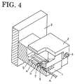
- the holding jig J is, as shown in FIGS. 2 to 4, comprised of a terminal holder 1 and a lid 2.
- the terminal holder 1 is secured to the base B via a base plate 3, and the lid 2 is pivotally coupled to one side of the terminal holder 1 via a pin 4.
- a multitude of terminal insertion grooves 5 extending in forward and backward directions or along an insertion direction of the terminals T are arrayed substantially side by side in the terminal holder 1, and are at least partly opened and closed as the lid 2 is pivoted to a first, preferably substantially horizontal position (FIG. 2) and to a second, preferably substantially vertical position (FIG. 3), respectively.
- the front ends of the terminal insertion grooves 5 are substantially open in the front surface of the terminal holder 1.
- a magnet 6 is mounted on the other side of the terminal holder 1, and a magnetically attachable portion 7 and a grip 8 are provided at the leading end of the lid 2. Further, a locking member 9 preferably made of a leaf spring in the form of saw teeth and extending toward the back side is mounted on the lid 2. When the lid 2 is closed, it is attached to the terminal holder 1 due to the magnetic attraction acting between the magnetically attachable portion 7 and the magnet 6, and the locking member 9 projects into the terminal insertion grooves 5 obliquely backward.
- the terminal T is inserted through the front end opening of the terminal insertion groove 5 as shown in FIG. 5(A), it is further inserted into the terminal insertion groove 5 while warping or bending or deflecting the locking member 9 upward or away from the terminal insertion groove 5 as shown in FIGS. 5(B) and 5(C).
- a tubular portion a" at the leading end of the terminal T passes the locking member 9, the locking member 9 is elastically restored substantially to its original state as shown in FIG. 5(D). If the terminal T is pulled in this state as shown in FIG. 5(E), the leading end of the locking member 9 engages a step b" of the terminal T to prevent the terminal T from coming out of the terminal insertion groove 5. Therefore, the terminal T is held without hanging.
- the base B Upon completion of the subassembly V, the base B is rotated to invert the holding jig J upside down as shown in FIG. 6. At this time, the lid 2 is not opened by the action of gravity since being attached to the terminal holder 1 by the magnetic force of the magnet 6.
- the terminal T Before being transferred to a subsequent process, the terminal T is taken out from the holding jig J by pushing the grip 8 down and disengaging the magnetically attachable portion 7 from the magnet 6 to open the lid 2 and by pushing the terminal T and the wire A together down as shown in FIG. 7.
- the terminal T can be easily taken out from the holding jig J by such an operation.
- the lid 2 needs to be closed for a succeeding terminal inserting operation after the terminal T is taken out from the holding J. Even if it is forgotten to close the lid 2 at this time, the leading end of the lid 2 is received by a stopper S located below the base B. Thus, the lid 2 is closed by the action of gravity when the holding jig J is returned to its erect position by the rotation of the base B. Therefore, a reduction in operability due to an operation error can be prevented.
- the terminal and the wire can be easily taken out by being pushed down together if the lid is opened with the holding jig inserted upside down by the rotation of the base, operability can be improved.
Landscapes
- Engineering & Computer Science (AREA)
- Manufacturing & Machinery (AREA)
- Manufacturing Of Electrical Connectors (AREA)
Abstract

Description
- The present invention relates to a terminal temporary holding jig for temporarily holding a later-inserted terminal, in particular when subassemblies forming a wiring harness are manufactured in an automatic terminal inserting apparatus. Furthermore, the invention relates to such an automatic terminal inserting apparatus.
- Generally, when an automotive wiring harness comprised of a multitude of wires is manufactured, subassemblies is first formed of a relatively smaller number of wires, and the wiring harness is formed by combining a plurality of subassemblies.
- The subassemblies may include later-inserted terminals which are not inserted into connector housings until they are formed into the wiring harness or are connected with devices equipped in an automotive vehicle. If these later-inserted terminals are left hanging, the wires connected therewith may be entangled with other wires to hinder a later process or to deform the terminals themselves, making the insertion of the terminals into the connector housings impossible.
- As a countermeasure, it may be considered to temporarily hold a later-inserted terminal during the manufacturing of a subassembly in an automatic terminal inserting apparatus using a temporary holding jig disclosed, for example, in Japanese Unexamined Patent Publication No. 6-199664 (Japanese Unexamined Patent Publication No. 8-64333).
- However, with the above jig, the terminal and the wire have to be slid along longitudinal direction when the terminal is taken out from the jig to be transferred to a later process, presenting a poor operability.
- In view of this problem, an object of the present invention is to provide a terminal temporary holding jig and an automatic terminal inserting apparatus with which a later-inserted terminal can be securely held and quickly taken out.
- This object is solved according to the invention by a terminal temporary holding jig according to
claim 1 and by an automatic terminal inserting apparatus according toclaim 6. Preferred embodiments of the invention are subject of the dependent claims. - According to the invention, there is provided a terminal temporary holding jig for an automatic terminal inserting apparatus, comprising:
- a terminal holder which is to be secured to a base of the automatic terminal inserting apparatus,
- one or more terminal insertion grooves formed in the terminal holder for at least partially accommodating one or more terminals to be inserted thereinto,
- a lid for at least partly opening and closing the terminal insertion grooves and
- a locking member provided in the lid,
wherein, when the lid is substantially closed, the locking member at least partly projects into the terminal insertion grooves so as to hold or lock the terminal in the terminal insertion groove. -
- According to a preferred embodiment, the locking member extends obliquely backward into the terminal insertion groove when the lid is in its substantially closed position.
- Preferably, if a terminal is inserted through a front end opening of the terminal insertion groove when the lid is substantially closed, the leading end of the locking member can engage a step of the terminal.
- According to a further preferred embodiment, there is provided a terminal temporary holding jig in or for an automatic terminal inserting apparatus, comprising:
- a terminal holder secured to a base of the automatic terminal inserting apparatus,
- a lid for opening and closing terminal insertion grooves formed in the terminal holder and extending in forward and backward directions, and
- a locking member provided in the lid,
wherein, when the lid is closed, it is held by the terminal holder and the locking member projects into the terminal insertion grooves obliquely backward, and if a terminal is inserted through a front end opening of the terminal insertion groove in this state, the leading end of the locking member engages a step of the terminal. -
- In the above holding jig, the later-inserted terminal inserted into the terminal insertion groove is securely held without coming out therefrom by the engagement with the locking member.
- Further, when the lid is opened with the holding jig inverted upside down by the rotation of the base, the terminal can be easily taken out by being pushed down together with the wire.
- Further preferably, a magnetic portion is provided on one of the base plate and the lid and a magnetically attachable portion is provided on the other of the base plate and the lid, and wherein the lid is fixed in its substantially closed position by the interaction of the magnetic portion and the magnetically attachable portion. Accordingly, the lid can be easily opened and closed.
- Further preferably, the lid is pivotably or rotatably mounted on the base plate.
- Most preferably, the locking member comprises a leaf spring in the form of saw teeth, each saw tooth preferably at least partly extending into a corresponding terminal insertion groove.
- According to the invention, there is further provided an automatic terminal inserting apparatus for mounting subassemblies forming a wiring harness by at least partly inserting terminals into corresponding connectors and pulling the terminals for verifying that they are properly inserted or locked, comprising one or more terminal temporary holding jigs according to the invention or an embodiment thereof.
- According to a preferred embodiment, the terminal temporary holding jigs are pivotally or rotatably provided on or in a frame of the automatic terminal inserting apparatus so as to rotate around the longitudinal direction of a base thereof.
- Preferably, the automatic terminal inserting further comprises at least one stopper, wherein when the terminal temporary holding jig is rotated or pivoted a lid in its substantially open position is moved, preferably pivoted to its substantially closed position by an interaction with the stopper.
- These and other objects, features and advantages of the present invention will become apparent upon a reading of the following detailed description and accompanying drawings in which:
- FIG. 1 is a perspective view showing a used state of a terminal temporary holding jig according to a preferred embodiment of the invention,
- FIG. 2 is a perspective view showing the holding jig with a lid substantially closed,
- FIG. 3 is a perspective view showing the holding jig with the lid substantially opened,
- FIG. 4 is a perspective view partly in section showing a portion of the holding jig,
- FIGS. 5(A) to 5(E) are vertical sections showing a process of inserting a terminal into a terminal insertion groove of the holding jig,
- FIG. 6 is a front view of the holding jig inverted upside down, and
- FIG. 7 is a front view showing how the terminal is taken out from the holding jig.
-
- Hereinafter, one embodiment of the invention is described with reference to the accompanying drawings.
- A terminal temporary holding jig J according to a preferred embodiment of the invention is mounted on a base B of an automatic terminal inserting apparatus for temporarily holding a later-inserted terminal T not inserted into a connector housing C when a subassembly V is formed. The subassembly V formed at one side of the base B is taken out at the other side by or after the rotation or pivotal movement of the base B, and a next set of connector housings C are then set. The automatic terminal inserting apparatus inserts terminals T into a temporary holding jig J and preferably pulls the terminal T so as to verify that the terminal T is firmly held in or properly inserted into the temporary holding jig J and/or to verify that a holding member 9 (to be described later) is properly functioning.
- The holding jig J is, as shown in FIGS. 2 to 4, comprised of a
terminal holder 1 and alid 2. Theterminal holder 1 is secured to the base B via abase plate 3, and thelid 2 is pivotally coupled to one side of theterminal holder 1 via apin 4. A multitude ofterminal insertion grooves 5 extending in forward and backward directions or along an insertion direction of the terminals T are arrayed substantially side by side in theterminal holder 1, and are at least partly opened and closed as thelid 2 is pivoted to a first, preferably substantially horizontal position (FIG. 2) and to a second, preferably substantially vertical position (FIG. 3), respectively. The front ends of theterminal insertion grooves 5 are substantially open in the front surface of theterminal holder 1. - A
magnet 6 is mounted on the other side of theterminal holder 1, and a magneticallyattachable portion 7 and agrip 8 are provided at the leading end of thelid 2. Further, alocking member 9 preferably made of a leaf spring in the form of saw teeth and extending toward the back side is mounted on thelid 2. When thelid 2 is closed, it is attached to theterminal holder 1 due to the magnetic attraction acting between the magneticallyattachable portion 7 and themagnet 6, and thelocking member 9 projects into theterminal insertion grooves 5 obliquely backward. - In the manufacturing of the subassembly V using the holding jig J constructed as above, if the terminal T is inserted through the front end opening of the
terminal insertion groove 5 as shown in FIG. 5(A), it is further inserted into theterminal insertion groove 5 while warping or bending or deflecting thelocking member 9 upward or away from theterminal insertion groove 5 as shown in FIGS. 5(B) and 5(C). When a tubular portiona" at the leading end of the terminal T passes the
locking member 9, thelocking member 9 is elastically restored substantially to its original state as shown in FIG. 5(D). If the terminal T is pulled in this state as shown in FIG. 5(E), the leading end of thelocking member 9 engages a stepterminal insertion groove 5. Therefore, the terminal T is held without hanging. - Upon completion of the subassembly V, the base B is rotated to invert the holding jig J upside down as shown in FIG. 6. At this time, the
lid 2 is not opened by the action of gravity since being attached to theterminal holder 1 by the magnetic force of themagnet 6. - Before being transferred to a subsequent process, the terminal T is taken out from the holding jig J by pushing the
grip 8 down and disengaging the magneticallyattachable portion 7 from themagnet 6 to open thelid 2 and by pushing the terminal T and the wire A together down as shown in FIG. 7. The terminal T can be easily taken out from the holding jig J by such an operation. - The
lid 2 needs to be closed for a succeeding terminal inserting operation after the terminal T is taken out from the holding J. Even if it is forgotten to close thelid 2 at this time, the leading end of thelid 2 is received by a stopper S located below the base B. Thus, thelid 2 is closed by the action of gravity when the holding jig J is returned to its erect position by the rotation of the base B. Therefore, a reduction in operability due to an operation error can be prevented. - As described above, since the later-inserted terminal inserted into the terminal insertion groove is securely held therein without coming out by the engagement with the locking member in the inventive terminal temporary holding jig, a damage of the later-inserted terminal and entanglement of the wires can be prevented.
- Further, since the terminal and the wire can be easily taken out by being pushed down together if the lid is opened with the holding jig inserted upside down by the rotation of the base, operability can be improved.
-
- J
- terminal temporary holding jig
- T
- terminal
- a
- leading end tubular portion
- b
- step
- A
- wire
- B
- base
- 1
- terminal holder
- 2
- lid
- 3
- base plate
- 4
- pin
- 5
- terminal insertion groove
- 6
- magnet
- 7
- magnetically attachable portion
- 8
- grip
- 9
- locking member
Claims (9)
- A terminal temporary holding jig (J) for an automatic terminal inserting apparatus, comprising:a terminal holder (1) which is to be secured to a base (B) of the automatic terminal inserting apparatus,one or more terminal insertion grooves (5) formed in the terminal holder (1) for at least partially accommodating one or more terminals (T) to be inserted thereinto,a lid (2) for at least partly opening and closing the terminal insertion grooves (5) anda locking member (9) provided in the lid (2),
wherein, when the lid (2) is substantially closed, the locking member (9) at least partly projects into the terminal insertion grooves (5) so as to hold or lock the terminal (T) in the terminal insertion groove (5). - A terminal temporary holding jig according to claim 1, wherein the locking member (9) extends obliquely backward into the terminal insertion groove (5) when the lid (2) is in its substantially closed position.
- A terminal temporary holding jig according to one or more of the preceding claims, wherein if a terminal (T) is inserted through a front end opening of the terminal insertion groove (5) when the lid (2) is substantially closed, the leading end of the locking member (9) can engage a step (b) of the terminal (T).
- A terminal temporary holding jig according to one or more of the preceding claims, wherein a magnetic portion (6) is provided on one of the base plate (3) and the lid (2) and a magnetically attachable portion (7) is provided on the other of the base plate (3) and the lid (2), and wherein the lid (2) is fixed in its substantially closed position by the interaction of the magnetic portion (6) and the magnetically attachable portion (7).
- A terminal temporary holding jig according to one or more of the preceding claims, wherein the lid (2) is pivotably or rotatably mounted on the base plate (3).
- A terminal temporary holding jig according to one or more of the preceding claims, wherein the locking member (9) comprises a leaf spring in the form of saw teeth, each saw tooth preferably at least partly extending into a corresponding terminal insertion groove (5).
- An automatic terminal inserting apparatus for mounting subassemblies (V) forming a wiring harness by at least partly inserting terminals (T) into corresponding connectors and pulling the terminals (T) for veryfing that they are properly inserted or locked, comprising one or more terminal temporary holding jigs (J) according to one or more of the preceding claims.
- An automatic terminal inserting apparatus according to claim 7, wherein the terminal temporary holding jigs (J) are pivotally or rotatably provided on a frame of the automatic terminal inserting apparatus so as to rotate around the longitudinal direction of a base (B) thereof.
- An automatic terminal inserting apparatus according to claim 8, further comprising at least one stopper (S), wherein when the terminal temporary holding jig (J) is rotated or pivoted a lid (2) in its substantially open position is moved, preferably pivoted to its substantially closed position by an interaction with the stopper (S).
Applications Claiming Priority (2)
| Application Number | Priority Date | Filing Date | Title |
|---|---|---|---|
| JP20782699 | 1999-07-22 | ||
| JP20782699A JP3603681B2 (en) | 1999-07-22 | 1999-07-22 | Temporary terminal holding jig for automatic terminal insertion device |
Publications (2)
| Publication Number | Publication Date |
|---|---|
| EP1071177A1 true EP1071177A1 (en) | 2001-01-24 |
| EP1071177B1 EP1071177B1 (en) | 2004-05-06 |
Family
ID=16546164
Family Applications (1)
| Application Number | Title | Priority Date | Filing Date |
|---|---|---|---|
| EP00114175A Expired - Lifetime EP1071177B1 (en) | 1999-07-22 | 2000-07-12 | A terminal temporary holding jig and an automatic terminal inserting apparatus |
Country Status (4)
| Country | Link |
|---|---|
| US (1) | US6539616B1 (en) |
| EP (1) | EP1071177B1 (en) |
| JP (1) | JP3603681B2 (en) |
| DE (1) | DE60010384T2 (en) |
Families Citing this family (3)
| Publication number | Priority date | Publication date | Assignee | Title |
|---|---|---|---|---|
| US6885028B2 (en) * | 2002-03-25 | 2005-04-26 | Sharp Kabushiki Kaisha | Transistor array and active-matrix substrate |
| JP4351603B2 (en) * | 2004-09-28 | 2009-10-28 | 矢崎総業株式会社 | Terminal insertion device |
| DE102024002531A1 (en) * | 2024-08-03 | 2026-02-05 | Mercedes-Benz Group AG | Device and method for collecting pipes |
Citations (4)
| Publication number | Priority date | Publication date | Assignee | Title |
|---|---|---|---|---|
| EP0530763A1 (en) * | 1991-09-04 | 1993-03-10 | The Furukawa Electric Co., Ltd. | Aligning jig for loose wires |
| US5581873A (en) * | 1994-03-03 | 1996-12-10 | Sumitomo Wiring Systems, Ltd. | Temporary holding member for a wiring assembly manufacturing apparatus |
| US5630273A (en) * | 1994-08-24 | 1997-05-20 | Sumitomo Wiring Systems, Ltd. | Holding jig and method for temporarily retaining last-in terminals |
| US5683257A (en) * | 1994-09-14 | 1997-11-04 | Sumitomo Wiring Systems, Ltd. | Retainer for holding terminals in a unit structure and method of use thereof |
Family Cites Families (4)
| Publication number | Priority date | Publication date | Assignee | Title |
|---|---|---|---|---|
| US5355593A (en) * | 1992-06-24 | 1994-10-18 | J.M. Voith Gmbh | Device for transferring a fiber web |
| JPH10106371A (en) * | 1996-09-27 | 1998-04-24 | Harness Sogo Gijutsu Kenkyusho:Kk | Manufacture of wire harness |
| US5779501A (en) * | 1996-10-11 | 1998-07-14 | Ut Automotive Dearborn, Inc. | Connector |
| JP3396799B2 (en) * | 1997-07-31 | 2003-04-14 | 京セラエルコ株式会社 | Method for manufacturing contact with ground terminal of memory card |
-
1999
- 1999-07-22 JP JP20782699A patent/JP3603681B2/en not_active Expired - Fee Related
-
2000
- 2000-07-12 EP EP00114175A patent/EP1071177B1/en not_active Expired - Lifetime
- 2000-07-12 DE DE60010384T patent/DE60010384T2/en not_active Expired - Fee Related
- 2000-07-19 US US09/619,433 patent/US6539616B1/en not_active Expired - Fee Related
Patent Citations (4)
| Publication number | Priority date | Publication date | Assignee | Title |
|---|---|---|---|---|
| EP0530763A1 (en) * | 1991-09-04 | 1993-03-10 | The Furukawa Electric Co., Ltd. | Aligning jig for loose wires |
| US5581873A (en) * | 1994-03-03 | 1996-12-10 | Sumitomo Wiring Systems, Ltd. | Temporary holding member for a wiring assembly manufacturing apparatus |
| US5630273A (en) * | 1994-08-24 | 1997-05-20 | Sumitomo Wiring Systems, Ltd. | Holding jig and method for temporarily retaining last-in terminals |
| US5683257A (en) * | 1994-09-14 | 1997-11-04 | Sumitomo Wiring Systems, Ltd. | Retainer for holding terminals in a unit structure and method of use thereof |
Also Published As
| Publication number | Publication date |
|---|---|
| JP3603681B2 (en) | 2004-12-22 |
| DE60010384T2 (en) | 2005-05-04 |
| US6539616B1 (en) | 2003-04-01 |
| EP1071177B1 (en) | 2004-05-06 |
| JP2001035277A (en) | 2001-02-09 |
| DE60010384D1 (en) | 2004-06-09 |
Similar Documents
| Publication | Publication Date | Title |
|---|---|---|
| JP2934821B2 (en) | Electrical connector with terminal position assurance mechanism | |
| JP3596729B2 (en) | Connector mating structure | |
| JP2789973B2 (en) | connector | |
| TW318243B (en) | ||
| JP2574771Y2 (en) | connector | |
| JP2747507B2 (en) | Terminal insertion method | |
| EP1075052A1 (en) | Lever-type electrical connector | |
| JP3263899B2 (en) | Electrical connector with terminal position assurance mechanism | |
| JP2000058200A (en) | Connector fitting structure | |
| JPH07282883A (en) | Connector housing | |
| JPH05315027A (en) | Lock mechanism for connector | |
| JPH07245139A (en) | Double locking connector and unlocking structure thereof | |
| EP1071177B1 (en) | A terminal temporary holding jig and an automatic terminal inserting apparatus | |
| JPH0917485A (en) | Connector with rear holder | |
| GB2260866A (en) | Electrical connector with hinged contact holder | |
| JPH11512215A (en) | Connector assembly with actuation slide | |
| JP3066714B2 (en) | Lock mechanism | |
| KR101018904B1 (en) | Connector device | |
| JP3470644B2 (en) | Wire harness connector holding jig | |
| US7201995B2 (en) | Battery positive cover | |
| JP2000068003A (en) | Mating detection connector | |
| JP7388835B2 (en) | Connector and its assembly method | |
| JP2000340289A (en) | Electronic equipment having connector disconnection prevention mechanism | |
| JP3752961B2 (en) | connector | |
| JPH053059A (en) | Connector with lever |
Legal Events
| Date | Code | Title | Description |
|---|---|---|---|
| PUAI | Public reference made under article 153(3) epc to a published international application that has entered the european phase |
Free format text: ORIGINAL CODE: 0009012 |
|
| 17P | Request for examination filed |
Effective date: 20000803 |
|
| AK | Designated contracting states |
Kind code of ref document: A1 Designated state(s): DE FR GB |
|
| AX | Request for extension of the european patent |
Free format text: AL;LT;LV;MK;RO;SI |
|
| AKX | Designation fees paid |
Free format text: DE FR GB |
|
| GRAP | Despatch of communication of intention to grant a patent |
Free format text: ORIGINAL CODE: EPIDOSNIGR1 |
|
| GRAS | Grant fee paid |
Free format text: ORIGINAL CODE: EPIDOSNIGR3 |
|
| GRAA | (expected) grant |
Free format text: ORIGINAL CODE: 0009210 |
|
| AK | Designated contracting states |
Kind code of ref document: B1 Designated state(s): DE FR GB |
|
| PG25 | Lapsed in a contracting state [announced via postgrant information from national office to epo] |
Ref country code: FR Free format text: LAPSE BECAUSE OF FAILURE TO SUBMIT A TRANSLATION OF THE DESCRIPTION OR TO PAY THE FEE WITHIN THE PRESCRIBED TIME-LIMIT Effective date: 20040506 |
|
| REG | Reference to a national code |
Ref country code: GB Ref legal event code: FG4D |
|
| REF | Corresponds to: |
Ref document number: 60010384 Country of ref document: DE Date of ref document: 20040609 Kind code of ref document: P |
|
| PG25 | Lapsed in a contracting state [announced via postgrant information from national office to epo] |
Ref country code: GB Free format text: LAPSE BECAUSE OF NON-PAYMENT OF DUE FEES Effective date: 20040806 |
|
| PLBE | No opposition filed within time limit |
Free format text: ORIGINAL CODE: 0009261 |
|
| STAA | Information on the status of an ep patent application or granted ep patent |
Free format text: STATUS: NO OPPOSITION FILED WITHIN TIME LIMIT |
|
| GBPC | Gb: european patent ceased through non-payment of renewal fee |
Effective date: 20040806 |
|
| EN | Fr: translation not filed | ||
| 26N | No opposition filed |
Effective date: 20050208 |
|
| PGFP | Annual fee paid to national office [announced via postgrant information from national office to epo] |
Ref country code: DE Payment date: 20070705 Year of fee payment: 8 |
|
| PG25 | Lapsed in a contracting state [announced via postgrant information from national office to epo] |
Ref country code: DE Free format text: LAPSE BECAUSE OF NON-PAYMENT OF DUE FEES Effective date: 20090203 |