EP1071160A2 - Repeater with side-to-side arranged antennas and with adaptive feedback signal cancellation circuit - Google Patents
Repeater with side-to-side arranged antennas and with adaptive feedback signal cancellation circuit Download PDFInfo
- Publication number
- EP1071160A2 EP1071160A2 EP00115574A EP00115574A EP1071160A2 EP 1071160 A2 EP1071160 A2 EP 1071160A2 EP 00115574 A EP00115574 A EP 00115574A EP 00115574 A EP00115574 A EP 00115574A EP 1071160 A2 EP1071160 A2 EP 1071160A2
- Authority
- EP
- European Patent Office
- Prior art keywords
- signal
- radio frequency
- repeater
- antenna
- housing
- Prior art date
- Legal status (The legal status is an assumption and is not a legal conclusion. Google has not performed a legal analysis and makes no representation as to the accuracy of the status listed.)
- Withdrawn
Links
Images







Classifications
-
- H—ELECTRICITY
- H04—ELECTRIC COMMUNICATION TECHNIQUE
- H04B—TRANSMISSION
- H04B7/00—Radio transmission systems, i.e. using radiation field
- H04B7/14—Relay systems
- H04B7/15—Active relay systems
- H04B7/155—Ground-based stations
- H04B7/15564—Relay station antennae loop interference reduction
- H04B7/15571—Relay station antennae loop interference reduction by signal isolation, e.g. isolation by frequency or by antenna pattern, or by polarization
-
- H—ELECTRICITY
- H04—ELECTRIC COMMUNICATION TECHNIQUE
- H04B—TRANSMISSION
- H04B1/00—Details of transmission systems, not covered by a single one of groups H04B3/00 - H04B13/00; Details of transmission systems not characterised by the medium used for transmission
- H04B1/59—Responders; Transponders
-
- H—ELECTRICITY
- H01—ELECTRIC ELEMENTS
- H01Q—ANTENNAS, i.e. RADIO AERIALS
- H01Q1/00—Details of, or arrangements associated with, antennas
- H01Q1/007—Details of, or arrangements associated with, antennas specially adapted for indoor communication
-
- H—ELECTRICITY
- H01—ELECTRIC ELEMENTS
- H01Q—ANTENNAS, i.e. RADIO AERIALS
- H01Q21/00—Antenna arrays or systems
- H01Q21/28—Combinations of substantially independent non-interacting antenna units or systems
-
- H—ELECTRICITY
- H01—ELECTRIC ELEMENTS
- H01Q—ANTENNAS, i.e. RADIO AERIALS
- H01Q21/00—Antenna arrays or systems
- H01Q21/29—Combinations of different interacting antenna units for giving a desired directional characteristic
-
- H—ELECTRICITY
- H01—ELECTRIC ELEMENTS
- H01Q—ANTENNAS, i.e. RADIO AERIALS
- H01Q23/00—Antennas with active circuits or circuit elements integrated within them or attached to them
-
- H—ELECTRICITY
- H01—ELECTRIC ELEMENTS
- H01Q—ANTENNAS, i.e. RADIO AERIALS
- H01Q3/00—Arrangements for changing or varying the orientation or the shape of the directional pattern of the waves radiated from an antenna or antenna system
- H01Q3/26—Arrangements for changing or varying the orientation or the shape of the directional pattern of the waves radiated from an antenna or antenna system varying the relative phase or relative amplitude of energisation between two or more active radiating elements; varying the distribution of energy across a radiating aperture
- H01Q3/2605—Array of radiating elements provided with a feedback control over the element weights, e.g. adaptive arrays
- H01Q3/2611—Means for null steering; Adaptive interference nulling
-
- H—ELECTRICITY
- H01—ELECTRIC ELEMENTS
- H01Q—ANTENNAS, i.e. RADIO AERIALS
- H01Q3/00—Arrangements for changing or varying the orientation or the shape of the directional pattern of the waves radiated from an antenna or antenna system
- H01Q3/26—Arrangements for changing or varying the orientation or the shape of the directional pattern of the waves radiated from an antenna or antenna system varying the relative phase or relative amplitude of energisation between two or more active radiating elements; varying the distribution of energy across a radiating aperture
- H01Q3/2605—Array of radiating elements provided with a feedback control over the element weights, e.g. adaptive arrays
- H01Q3/2647—Retrodirective arrays
Definitions
- tower-mounted repeater systems are often used to extend the range of a cell site, to provide null fill in regions that are RF blocked, such as by bills or trees, and/or to provide enhanced "in-building" coverage, via directing the signal power to the desired structures, such as a building 30.
- the typical repeater system comprises three basic parts shown in FIG. 2 and FIG. 3: the link antenna 22 which is directed/aimed at the wireless base station (BS); the amplifying electronics "box” 24, and the broadcast antenna 26 - which is directed towards the area of interest.
- the link antenna 22 is highly directive (high gain) with a very narrow beam, since it only needs to "see” the base station.
- the broadcast antenna 26 is more defined by the beamwidth necessary to cover the intended area.
- the electronics box 24 may contain an assortment of diplexers, filters, splitters, and RF amplifiers.
- the output power is mostly determined by the sum of the two passive antenna (link and broadcast) gains and the maximum (linear) output power of the amplifier(s).
- the system gain is determined by the sum of the passive antenna gains, plus the gain of the amplifier stage. This is limited by the isolation (or mutual coupling) between the two (broadcast and link) antennas. The isolation depends on the antenna type, front to back (F/B) ratio and beamwidth.
- the isolation between antennas is therefore about 50 dB, which is the sum of the two F/B ratios (25 dB + 25 dB).
- a safety factor of about 20 dB is recommended, which translates to an active (amplifier) gain to about 30 dB (50 - 20).
- a well designed antenna should have a front to back ratio (F/B) better than 20 dB.
- F/B front to back ratio
- the F/B can be as high as 40 dB.
- the directivity which means that the antenna's beamwidth is narrowed.
- this might prove disadvantageous, since the coverage area (sector width) is reduced.
- Orientation and separation distance of the antennas is also a factor.
- the propagation path loss is proportional to 1/R, where R is the radius or distance between the two antennas (note, it is 1/R 2 for the far field).
- R is the radius or distance between the two antennas (note, it is 1/R 2 for the far field).
- the propagation loss is about 24 dB. This therefore increases the isolation between the two antennas by 24 dB.
- Existing indoor repeater systems typically employ a separate link antenna 32, either on the roof, or on the side of a building (FIG. 4).
- the RF power is routed to the electronics portion of the repeater via a coaxial cable 34, often with an amplifier stage (not shown) in between.
- the indoor RF distribution system is either one or more antennas 36, or some other RF emission/reception mechanism, such as Radiax® (leaky wave) cable, or RF stripline cable 38.
- Radiax® leaky wave
- RF stripline cable 38 RF stripline cable
- indoor repeaters require accurate orientation (labor intensive) between the two antennas to insure maximum RF isolation, and to prevent signal feedBack and therefore "ringing" in the circuit.
- This invention is further directed to a method and apparatus for improving the isolation between donor and null antennas in a repeater system.
- repeaters are used to extend coverage of cell sites (base stations) to areas that have low signal reception power, and therefore low signal to noise ratios.
- One of the principle technology drivers is that of system gain. That is, the higher the gain, the greater the range (distance) and coverage area for the system.
- a limiting characteristic for repeaters is that of the feedback loop, or conversely, the isolation between the two opposing antennas (or sensors). That is, the total front to back (F/B) ratio for the system, or isolation, must be higher than the desired gain.
- repeaters employ at least one "link” or “donor” antenna which communicates with the base station and at least one broadcast, coverage, or “null” antenna which communicates with the remote stations or subscribers.
- the isolation between link and null antennas is equal to the total gain plus some margin, typically around 10 to 15 dB. Therefore, the system gain will in general be less than the isolation minus the margin. For example, if the isolation between antennas is around 60 dB, then the maximum system gain allowed will be about 45 dB. For PCS frequencies, these figures result in a repeater range of less than 100 feet.
- the F/B ratio (or isolation) is typically limited to a value below 80 dB or so. This therefore allows a total system gain of no more than 65 dB, which limits the system range to a few hundred feet or less.
- a modular repeater comprises a housing having a pair of substantially 180° oppositely facing surfaces, at least one antenna element mounted to each of said surfaces for radiating energy in a direction opposite to that of an antenna element mounted to the other of said surfaces, and an electronic circuit mounted within said housing and operatively coupling signals between at least one antenna element on each of said oppositely facing surfaces of said module.
- the invention also provides a method and apparatus for improving isolation between donor and null antennas in a repeater system.
- the described embodiment of this aspect of the invention provides an adaptive cancellation approach which removes a significant portion (between 10 dB and 40 dB), of the feedback signal power, therefore increasing the total system isolation by the same amount (10 to 40 dB).
- This additional isolation can be used to achieve greater system gain, and therefore significantly extend the range of the system. This is especially useful in the side-side repeater technology approach mentioned above and described in the above-referenced application.
- the cancellation scheme uses digitally processed information to generate a signal, which, when added to the original input signal, cancels the feedback signal.
- FIGS. 5 and 6 show an architecture for a two antenna system, in which each antenna operates in both the transmit and receive mode.
- the first antenna 52 might be used to receive an incoming RF signal from a transmitter or from another repeater, that is, in the link mode. This antenna and the associated circuitry to be described below would therefore usually operate in the frequency band of the incoming RF signal or signals to be received.
- the other antenna 54 would be utilized in the broadcast/repeat mode to transmit (and receive) signals to the user equipment, such as a remote handset or terminal, or to transmit a signal to a further repeater in a system using multiple repeaters to broadcast or distribute signals. Therefore, this second antenna 54 and its associated circuits, described below, would usually operate in the frequency band of the remote handset or terminal.
- Frequency diplexers (D) 62, 64 are used in the electronics module 60, to separate the power for each path. For example, RF power received on antenna 52 is routed through the diplexer 62 through a first circuit or path. This first circuit includes a filter 66 to attenuate the reverse link band, an amplifier 68 to amplify the RF, and then another filter 70, used to protect the amplifier 68 from signal power on the other circuit or path. The second diplexer 64 then delivers the signal to antenna 54 which retransmits the signal.
- antenna 54 receives a signal which is fed through diplexer 64 to a second circuit or path including similar filters 72, 74 and a similar amplifier 76 which operate in the same manner as the first circuit and feed a signal through a diplexer 62 to be transmitted at the antenna 52.
- FIG. 6 shows two sets of antennas: 52a, 54a and 52b, 54b, two antennas for the link mode and two for the broadcast/repeat mode.
- the antennas 52a, 52b on one side may be used for the link mode, as described above, one as the downlink antenna and one as an uplink antenna.
- the two antennas 52b, 54b on the other side would be used in the broadcast/repeat mode, as described above, one as an uplink antenna and one as a downlink antenna.
- Similar electronic circuits or paths including filters and amplifiers are interposed between the respective pairs of antennas 52a, 54a and 52b, 54b. However, because separate pairs of antennas are provided, no frequency diplexers are required in this case.
- the filters 66, 70, 72, 74 are selected so as to be sufficient to reduce the out-of-band signals.
- the filters are usually band pass types.
- the band pass bandwidth will usually be around 15 Mhz, commensurate with the bandwidth of PCS bands C, D, E, F, etc. Cut off and roll-off are more performance and spec oriented, and depend on circuit design.
- the amplifier elements 68, 76 comprise relatively low power, linear integrated circuit chip components, such as monolithic microwave integrated circuit (MMIC) chips. These chips may comprise chips made by the Gallium Arsenide (GaAs) heterojunction transistor manufacturing process. However, silicon process chips or CMOS process chips might also be utilized.
- MMIC monolithic microwave integrated circuit
- MMIC power amplifier chips Some examples of MMIC power amplifier chips are as follows:
- FIGS. 7, 8 and 16 show examples of the physical systems or modules 50, 50a, and 50b.
- FIGS. 7 and 8 correspond respectively to the systems described above with reference FIGS. 5 and 6.
- microstrip patches are used for the antenna elements 52, 54 (FIG. 7) and 52a, 52b, 54a, 54b (FIG. 8).
- the two antennas (Tx and Rx) on each face of the module in FIG. 8 operate similarly to the single Tx/Rx antenna element on each face in FIG. 7.
- the module/box or housing 50, 50a may be a metal box containing a DC power supply or DC power converter, amplifiers, filters and diplexers (if required), as described above with reference to FIGS. 5 and 6.
- the electronics are inside the box or module and may be discrete parts, connected together via SMA connectors. For lower power systems, the electronics can be surface mount PCB.
- FIG. 16 illustrates an approach which uses an array of antenna elements in order to increase the passive gain.
- the example shown in FIG. 16 uses two columns of patch array antennas on one face of the module, designated by reference numerals 54a through 54h.
- the antenna patches 54a through 54d are designated as receive (Rx) antennas in the embodiment shown on FIG. 16 while the antenna elements 54e through 54h are designated as transmit (Tx) antenna elements in this embodiment.
- Rx receive
- Tx transmit
- the respective antennas of FIGS. 7, 8 and 16 are "fixed" in position and orientation.
- the position and orientation of antennas is designed to assure maximum isolation between the antennas and to receive and transmit a given signal, and therefore maximize system gain.
- This isolation between antennas is controlled/maximized (and mutual coupling minimized) in the following ways:
- Design of the antennas, beams, and (control of) F/B ratios assures adequate isolation between the two opposing antennas (or antenna sets).
- the antennas' F/B ratios or isolation is the largest limiter for the total system gain.
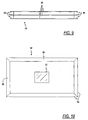
- a small lamp, LED, or other display element 100 can be used (see FIGS. 7 and 8) with appropriate RF power sensing electronics 80 (see FIGS. 5 and 6) to aid the provider/user/customer in orienting the unit or module 50 or 50a or 50b with a link antenna directed/pointed towards a base station, such that sufficient signal power is being received, i.e., at or above some predetermined threshold.
- repeater modules can be used in a number of applications, a few examples of which are as follows.
- the module 50 or 50a can be mounted on a wall or window, at or near a location where the RF signal power from a nearby base station is at its maximum power level (within the building). Power for each module can be via either a 120 volt cord and plug 102, or with a 120 volt plug connection 104, built directly into the module (see FIGS. 12 and 13). Both allow very simple installation, by the customer. Generally, the RF signal is received, at a power level above the noise floor, from a nearby base station (with the module placed in a location facing the base station), and the repeater re-radiates the (amplified) RF signal into the building. Additionally, signals from remote units (handsets/cellphones) within the building are received by the modules 50 (50a, 50b), amplified, and re-radiated back to the base station 200.
- a plurality of repeater modules 50 or 50a or 50b are placed at various locations within a building, "daisy chained” together, to provide greater coverage within the building.
- Power for each module can be via either a 120 volt cord and plug 102, or with a 120 volt plug connection 104, built directly into the module (see FIGS. 12 and 13). Both allow very simple installation, by the customer. This aids in providing coverage to the side of the building opposite to the base station, or any other RF null or "blank" areas within the building.
- the provider or customer can cheaply and easily install two or more modules, to provide coverage to various area(s) of the building, such as the side opposite the side nearest the base station, where the RF signal level (from the base station) has low Signal to Noise (ratio), or where there is no signal at all.
- a single module can be installed on a tower, instead of a more conventional unit requiring discrete antennas. This provides a smaller more economical package, and less labor (time) and effort in orienting the antennas to assure adequate isolation between the antennas.
- a single module can be installed on a tower, in the same fashion as above, realizing the same benefits.
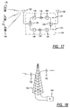
- FIG. 17 shows a block diagram of a conventional repeater system, showing three distinct elements: the link (or “donor") antenna, the coverage (or “null”) antenna 122, and the repeater electronics 124.
- the typical repeater electronic system 124 incorporates bandpass filters 126, for the uplink and downlink bands, as well as power amplifiers 128 and frequency diplexers 130.
- the filters 126 and amplifiers 128 are arranged as a pair of signal transmission circuits 131 (downlink) and 133 (uplink).
- a first filter 126 attenuates the bandwidth of incoming communications signals
- an amplifier 128 amplifies the signals from the first filter
- a second filter 126 located at the output of the amplifier protects the amplifier 128 from signal power in the other branches of the circuits 131, 133.
- the illustrated system in FIG. 17 is based on a "straight through" design, in which the signals go in a single direction through each branch or path (i.e., uplink and downlink) of the system.
- FIG. 18 shows a diagram of a typical repeater tower 125, with the system of FIG. 17, including the link (or “donor") antenna 120, the coverage (or “null”) antenna 122, and the repeater electronics 124.
- This system could also be installed on the top of a building, or within a building (for in-building coverage).
- FIG. 19 shows a similar system to that of FIG. 17, but with four distinct input/output ports. In this system, the signals from each path are not combined by frequency diplexers. Additionally, this system requires four, rather than two, antennas. Accordingly, FIG. 19 shows two donor antennas 120a and 120b, designated as the downlink and uplink to the base station (BS). Similarly, on the broadcast or coverage side, two null antennas 122a, 122b are shown, one functioning as the uplink and one as the downlink antenna relative to the remote units or subscriber equipment 135.
- BS base station
- FIG. 20 shows a tower arrangement, using the four-port system of FIG. 19.
- the respective downlink and uplink antennas 120a, 122a and 120b, 122b between the base station and the remotes are illustrated on the tower 125, with the electronics 124a of FIG. 19 being located at the base of the tower 125.
- FIG. 21 shows a block diagram of one path through a repeater system.
- Some of the transmitted signal energy couples back (through space, or through the electronics) into the receive antenna.
- the feedback signal, f(t) which is simply a delayed version (attenuated) of the original signal, S(t). Therefore, the composite signal, S(t) + f(t), is fed into the amplifier, with output G(S(t) + f(t)).
- the new feedback signal it G f(t).
- the propagation of this signal, back to the input antenna, will incur attenuation, H. Therefore, the amplified, attenuated signal at the input antenna will be H G f(t). If this signal is comparable in power to the original signal S(t), then the amplifier 128 will go unstable, and oscillate (ring). This oscillation will cause severe distortion in the desired signal.
- FIG. 22 shows the same circuit as FIG. 21; however, adding an adaptive cancellation circuit 140.
- the goal of this circuit 140 is to create a inverse f(t) signal -f(t) (a 180 degree shifted f(t) signal), and sum it with the input signal; including the feedback signal, f(t) at a summing junction 145, and thereby remove the feedback signal f(t).
- FIG. 23 shows a general block diagram (high level) of one form of the adaptive cancellation circuit 140.
- the input (RF) signal is summed at the junction 145 with a modulated signal constructed via a digitally adaptive process, to destructively interfere with the feedback signal embedded in the input composite signal.
- the composite signal, S(t) + f(t) is digitally sampled and digitally processed via a digital signal processor (DSP) 150, which computes an intermediate signal for a modulator 152.
- DSP digital signal processor
- the modulator 152 takes the intermediate signal, and a sample of the amplified (output) signal, and creates a near copy of the correct inverted f(t) signal -f(t).
- This process will work with many, if not most, of the digitally adaptive algorithms for feedback control. Additionally, this methodology does not require a injected signal (training or pilot tone, or wideband noise), for the adaptive process.
- the entire circuit shown in FIG. 23 may be designated as an "AC block" 155.
- FIG. 24 shows the circuit 140 in further detail.
- the DSP 150 is a combination of an RF downconverter 162 to shift the signal to an intermediate frequency that allows digital sampling, an analog-to-digital (A/D) converter 162 which digitizes the analog signal, and a processor 164 which performs the required operations to compute the intermediate signal.
- the modulator 152 is a combination of a controllable attenuator 166, and an I/Q modulator 168. Additional details shown in FIG. 24 include respective couplers 172 and 174 which couple the signals from the signal path to and from the adaptive cancellation circuit 140, a first coupler 172 being interposed between the summation junction 145 and the filter 126 and the second coupler 174 being at the output of the power amplifier 128.
- respective delay lines 182 and 184 may be employed at either end of the RF path, one just prior to the summing junction 145 and one subsequent to the coupler 174.
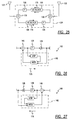
- FIG. 25 shows a block diagram of a repeater system, similar to that of FIG. 17, however using adaptive cancellation (AC) circuit blocks 155, details of which are shown in FIGS. 26 and 27, as well as in FIGS. 23 and 24.
- the "direction" of the circuit (AC block) 155 in each RF path has been taken into account.
- each (uplink, downlink) path has a separate AC circuit block 155.
- FIGS. 26 and 27 show the directional characteristics of the AC circuit blocks 155, whether for the downlink or uplink path.
- the blocks are "mirror images" of one another, differing by the direction of the desired signal, with the arrows 175 denoting the directionality of each circuit 155, in FIGS. 25, 26 and 27.
- FIGS. 29 and 31 show block diagrams of the adaptive cancellation (AC) approach, applied to side-to-side repeater systems, such as the ones shown and described above.
- FIG. 28 shows a side-to-side repeater having a body or housing 192 having opposed flat surfaces. To each of these opposed flat surfaces, there is mounted a single patch antenna element 194, 196, respectively comprising the null and donor antennas. An equivalent circuit diagram is shown in FIG. 29. It will be understood that the circuit components of FIG. 29, including the adaptive cancellation (AC) circuits, may be carried in the body or housing 192.
- FIG. 30 shows a side-to-side repeater structure 90a having a similar body or housing 192a which mounts separate uplink and downlink transmit (Tx) and receive (Rx) patch antenna elements for each of the null and donor antennas.
- Tx and Rx null antennas are designated by reference numerals 194a and 194b, while the respective Tx and Rx donor antenna elements are designated by reference numerals 196a and 196b.
- the circuits shown in FIG. 31 may be mounted to (in) the body (housing) 192a.
- the electronics i.e., the adaptive cancellation circuits
- the electronics may be carried on/in the body/housing 192, 192a of the antenna element in the side-to-side repeater structures of FIGS. 28 and 30, permitting a tower-top modular repeater installation, in addition to the other advantages, and/or use in other applications as more fully discussed and described in the above-referenced prior application.
- FIGS. 28 and 29 show the case for a single antenna (element) on each side, including frequency diplexers to separate each path (or frequency band).
- FIG. 30 and 31 show the approach when using separate Tx and Rx antennas, and therefore separate circuits, for each (uplink, downlink) path.
Landscapes
- Engineering & Computer Science (AREA)
- Computer Networks & Wireless Communication (AREA)
- Signal Processing (AREA)
- Radio Relay Systems (AREA)
- Mobile Radio Communication Systems (AREA)
- Variable-Direction Aerials And Aerial Arrays (AREA)
- Small-Scale Networks (AREA)
Abstract

Description
Claims (35)
- A modular repeater comprising:a housing having a pair of substantially 180° oppositely facing surfaces;at least one antenna element mounted to each of said surfaces for radiating energy in a direction opposite to that of the antenna element mounted to the other of said surfaces; andan electronic circuit mounted within said housing and operatively coupling signals between at least one antenna element on each of said pair of oppositely facing surfaces of said module.
- The repeater of claim 1 wherein a single antenna element is mounted to each of said oppositely facing surfaces of said housing and wherein said electronic circuit comprises a frequency diplexer operatively coupled with each of said antennas and a pair of signal transmission circuits coupled between said frequency diplexers.
- The repeater of claim 2 wherein each of said signal transmission circuits transmits a signal in one direction between said two antenna elements, each of said signal transmission circuits comprising a first filter to attenuate the bandwidth of incoming communications signals, an amplifier to amplify communications signals received from said first filter and a second filter located at an output of said amplifier to protect the amplifier from signal power in the other signal transmission circuit.
- The repeater of claim 1 wherein two antenna elements are mounted to each side of said module housing, one for transmitting communications signals and one for receiving communications signals.
- The repeater of claim 4 wherein said electronic circuit comprises a pair of signal transmission circuits, each forming a signal path between a transmitting antenna on one surface of said housing and a receiving antenna on the opposite surface of said housing, and wherein each of said signal transmission circuits comprises a first filter to attenuate the bandwidth of incoming communications signals, an amplifier which amplifies communications signals received from the first filter, and a second filter located at an output of said amplifier to protect the amplifier from signal power in the other of said signal transmission circuits.
- The repeater of claim 1 wherein each of said antenna elements comprises a microstrip patch.
- The repeater of claim 1 and further including a plurality of electromagnetic shunt elements located along surfaces of said housing which join said oppositely facing surfaces on which said antenna elements are located.
- The repeater of claim 1 wherein said electronic circuit includes a signal strength circuit and further including a display element operatively coupled with said signal strength circuit and visible from externally of said housing for indicating alignment of said modular repeater with a signal source providing signal strength equal to or greater than a preselected threshold.
- The repeater of claim 1 and further including one of an AC power cord and an AC power plug extending from said housing for coupling said modular repeater to a source of AC power, said AC power plug also being capable of mounting said modular repeater to an AC wall receptacle.
- An indoor repeater system for use in an enclosed area such as a building or the like, comprising a plurality of repeater modules, at least one of said repeater modules being mounted in a location for receiving an optimal signal level from a signal source external to said enclosed area, and the other repeater modules being placed for distributing communication signals around at least a desired portion of the enclosed area, each of said repeater modules comprising:a housing having a pair of substantially 180° oppositely facing surfaces;at least one antenna element mounted to each of said surfaces for radiating energy in a direction opposite to that of the antenna element mounted to the other of said surfaces; andan electronic circuit mounted within said housing and operatively coupling signals between at least one antenna element on each of said oppositely facing surfaces of said module.
- The modular repeater of claim 1, wherein each of said antenna elements comprises an array of microstrip patch elements.
- The repeater of claim 10, wherein each of said antenna elements comprises an array of microstrip patch elements.
- A method of constructing a modular repeater comprising:providing a housing having a pair of substantially 180° oppositely facing surfaces;mounting at least one antenna element mounted to each of said oppositely facing surfaces for radiating energy in a direction opposite to that of the antenna element mounted to the other of said oppositely facing surfaces;mounting an electronic circuit within said housing, said electronic circuit operatively coupling signals between at least one antenna element on each of said pair of oppositely facing surfaces of said module.
- The method of claim 13 including mounting two antenna elements to each side of said module housing, one for transmitting communications signals and one for receiving communications signals.
- The method of claim 13 and further including positioning a plurality of electromagnetic shunt elements along surfaces of said housing which join said oppositely facing surfaces on which said antenna elements are located.
- The method of claim 13 including said electronic circuit determining signal strength and further including coupling a display element with said electronic circuit and mounting said display element so as to be visible from externally of said housing for indicating alignment of said modular repeater with a signal source providing a signal strength equal to or greater than a preselected threshold.
- The method of claim 1 and further including extending one of an AC power cord and an AC power plug from said housing for coupling said modular repeater to a source of AC power, said AC power plug also being capable of mounting said modular repeater to an AC wall receptacle.
- A repeater system comprising:at least one donor antenna element for communicating with a base station and at least one null antenna element for communicating with a remote station;a radio frequency uplink path and a radio frequency downlink path coupled between said donor antenna and said null antenna; andan adaptive cancellation circuit in at least one of said radio frequency up link path and said radio frequency downlink path, which generates a cancellation signal, which when added to a radio frequency signal in either of said radio frequency uplink and radio frequency downlink paths, substantially cancels any feedback signal present in said radio frequency signal.
- The repeater system of claim 18 wherein said adaptive cancellation circuit comprises a digital signal processor circuit which receives an incoming radio frequency signal from one of said radio frequency uplink and downlink paths, said radio frequency signal having a feedback signal component, and which digitally samples and processes said incoming radio frequency signal to generate an intermediate frequency signal, and a modulator circuit which receives said intermediate frequency signal and a sample of a radio frequency output signal from said one of said radio frequency uplink and downlink paths and generates said cancellation signal.
- The system of claim 19 wherein said digital signal processor comprises a radio frequency downconverter which converts said incoming radio frequency signal to a lower frequency signal for digital sampling, an analog-to-digital converter coupled to the radio frequency downconverter, which analog-to-digital converter digitizes said lower frequency signal, and a processor coupled to the analog-to-digital converter which computes a desired intermediate frequency signal for the modulator.
- The system of claim 19 wherein said adaptive cancellation circuit further includes a summing junction which receives and sums said intermediate frequency signal and said incoming radio frequency signal.
- The system of claim 21 wherein said digital signal processor circuit receives an output of said summing junction.
- The system of claim 22 wherein said adaptive cancellation circuit further includes a filter coupled to receive the output of said summing junction and a power amplifier coupled to receive the output of said filter.
- The system of claim 20 wherein said modulator circuit comprises a controllable attenuator which receives and attenuates the radio frequency output signal and an I/Q modulator coupled to said attenuator and to said processor.
- The system of claim 18 wherein said repeater comprises:a housing having a pair of substantially 180° oppositely facing surfaces;at least one antenna element mounted to each of said surfaces for radiating energy in a direction opposite to that of the antenna element mounted to the other of said surfaces; andan electronic circuit mounted to said housing and operatively coupling signals between at least one antenna element on each of said pair of oppositely facing surfaces of said module.
- The system of claim 25 wherein said adaptive cancellation circuit forms a part of said electronic circuit.
- A method of operating a repeater system having at least one donor antenna element for communicating with a base station and at least one null antenna element for communicating with a remote station, and a radio frequency uplink path and a radio frequency downlink path coupled between said donor antenna and said null antenna, said method comprising:generating a cancellation signal at least one of said radio frequency uplink path and said radio frequency downlink path, which cancellation signal, when added to a radio frequency signal in either of said radio frequency uplink and radio frequency downlink paths, substantially cancels any feedback signal present in said radio frequency signal.
- The method of claim 27 wherein said generating comprises receiving an incoming radio frequency signal from one of said radio frequency uplink and downlink paths, said radio frequency signal having a feedback signal component, digitally sampling and processing said incoming radio frequency signal to generate an intermediate frequency signal, and using said intermediate frequency signal and a sample of a radio frequency output signal from said one of said radio frequency uplink and downlink paths to generate said cancellation signal.
- The method of claim 28 wherein said processing comprises downconverting said incoming radio frequency signal to a lower frequency signal for digital sampling, digitizing said lower frequency signal, and digitally computing a desired intermediate frequency signal using said digitized lower frequency signal.
- The system of claim 28 further including a summing said intermediate frequency signal and said incoming radio frequency signal.
- The method of claim 30 wherein said digitally processing follows said summing.
- The method of claim 31 further including filtering and power amplifying following said summing.
- The method of claim 29 wherein said generating further comprises controllably attenuating the radio frequency output signal and I/Q modulating following said attenuating.
- The method of claim 27 wherein said repeater further includes a housing having a pair of substantially 180° oppositely facing surfaces, and wherein said method includes mounting at least one antenna element to each of said surfaces for radiating energy in opposite directions; and mounting an electronic circuit within said housing for operatively coupling signals between at least one antenna element on each of said pair of oppositely facing surfaces of said module.
- A repeater system comprising:at least one donor antenna element for communicating with a base station and at least one null antenna element for communicating with a remote station; andan adaptive cancellation circuit which generates a cancellation signal, which when added to a radio frequency signal from either of said donor antenna and said null antenna, substantially cancels any feedback signal present in said radio frequency signal.
Applications Claiming Priority (4)
| Application Number | Priority Date | Filing Date | Title |
|---|---|---|---|
| US357032 | 1982-03-11 | ||
| US09/357,032 US6731904B1 (en) | 1999-07-20 | 1999-07-20 | Side-to-side repeater |
| US483234 | 2000-01-14 | ||
| US09/483,234 US6745003B1 (en) | 1999-07-20 | 2000-01-14 | Adaptive cancellation for wireless repeaters |
Publications (2)
| Publication Number | Publication Date |
|---|---|
| EP1071160A2 true EP1071160A2 (en) | 2001-01-24 |
| EP1071160A3 EP1071160A3 (en) | 2003-10-08 |
Family
ID=26999484
Family Applications (1)
| Application Number | Title | Priority Date | Filing Date |
|---|---|---|---|
| EP00115574A Withdrawn EP1071160A3 (en) | 1999-07-20 | 2000-07-19 | Repeater with side-to-side arranged antennas and with adaptive feedback signal cancellation circuit |
Country Status (8)
| Country | Link |
|---|---|
| EP (1) | EP1071160A3 (en) |
| JP (1) | JP4753459B2 (en) |
| KR (2) | KR100908862B1 (en) |
| CN (1) | CN1231078C (en) |
| AU (1) | AU763142B2 (en) |
| BR (1) | BR0003010A (en) |
| CA (1) | CA2313930A1 (en) |
| IL (1) | IL137078A (en) |
Cited By (17)
| Publication number | Priority date | Publication date | Assignee | Title |
|---|---|---|---|---|
| WO2002080303A1 (en) * | 2001-03-30 | 2002-10-10 | Telefonaktiebolaget Lm Ericsson | Antenna arrangement |
| WO2002095866A1 (en) * | 2001-05-22 | 2002-11-28 | Andrew Corporation | Repeater for radio signals |
| KR100385611B1 (en) * | 2001-06-01 | 2003-05-27 | 이노에이스(주) | Wireless interchange apparatus for mobile communication system |
| KR20030046577A (en) * | 2001-12-05 | 2003-06-18 | 포유텔레콤 주식회사 | Multi channel transmit-receive apparatus of radio relay system |
| EP1411584A1 (en) * | 2002-10-15 | 2004-04-21 | Samsung Electronics Co. Ltd. | Built-in antenna system for indoor wireless communications |
| WO2006068419A1 (en) * | 2004-12-21 | 2006-06-29 | Electronics And Telecommunications Research Institute | Isolation antenna for repeater |
| WO2006068418A1 (en) * | 2004-12-21 | 2006-06-29 | Electronics And Telecommunications Research Institute | H-type monopole isolation antenna |
| EP1775973A3 (en) * | 2005-10-13 | 2009-07-15 | Microset | Field extensor - repeater for GSM cellular telephone |
| WO2010017527A3 (en) * | 2008-08-07 | 2010-04-01 | Wal-Mart Stores, Inc. | Apparatus and method facilitating communication between components of a radio frequency identification system |
| WO2011057075A1 (en) * | 2009-11-06 | 2011-05-12 | General Electric Company | Apparatus and method for repeating communication messages in rail vehicle systems |
| US9014621B2 (en) | 2009-04-10 | 2015-04-21 | Nextivity, Inc. | Short-range cellular booster |
| EP1711928B1 (en) * | 2004-01-12 | 2015-08-26 | Nextivity, Inc. | Short-range cellular booster |
| US9526075B2 (en) | 2013-01-08 | 2016-12-20 | Whoop Wireless Llc | System, a device and a method for adjusting signal strength in a distributed amplifier system |
| EP3157102A1 (en) * | 2011-09-08 | 2017-04-19 | Intel Corporation | Overlapped and staggered antenna arrays |
| EP2051404B1 (en) * | 2007-10-15 | 2018-03-14 | Societe Francaise Du Radio Telephone (Sfr) | Access point to a network and wireless communication device therefor |
| CN111819731A (en) * | 2018-03-05 | 2020-10-23 | 康普技术有限责任公司 | Compact Multiband Feed for Small Cell Base Station Antennas |
| WO2021061447A1 (en) | 2019-09-23 | 2021-04-01 | Amphenol Antenna Solutions, Inc. | High gain single lens repeater platform |
Families Citing this family (20)
| Publication number | Priority date | Publication date | Assignee | Title |
|---|---|---|---|---|
| JP2005531202A (en) * | 2002-06-21 | 2005-10-13 | ワイデファイ インコーポレイテッド | Wireless local area network repeater |
| EP1597839B1 (en) * | 2003-02-26 | 2007-08-15 | Andrew Corporation | Cellular signal enhancer |
| JP4523817B2 (en) * | 2003-12-05 | 2010-08-11 | 株式会社エヌ・ティ・ティ・ドコモ | Wireless relay device |
| JP2008517496A (en) * | 2004-10-15 | 2008-05-22 | アーベーベー・リサーチ・リミテッド | Signal transmission system for driving a power semiconductor switch, and a converter having such a signal transmission system |
| WO2007004927A1 (en) * | 2005-07-04 | 2007-01-11 | Telefonaktiebolaget Lm Ericsson (Publ) | An improved repeater antenna |
| JP4670106B2 (en) * | 2005-08-12 | 2011-04-13 | ケイティー コーポレーション | Link antenna installation position selection method, cable device and terminal for indoor RF repeater |
| KR100859557B1 (en) * | 2005-12-26 | 2008-09-23 | 주식회사 케이엠더블유 | RF repeater |
| US7826801B2 (en) | 2006-03-07 | 2010-11-02 | Airpoint | Adaptive forward error corrector and method thereof, and TDD radio repeating apparatus using the same |
| EP1919101A3 (en) * | 2006-11-02 | 2009-08-19 | LG Telecom, Ltd. | Small-sized radio frequency type repeater |
| KR100844828B1 (en) * | 2006-11-24 | 2008-07-08 | 주식회사알에프윈도우 | Feedback Interference Cancellation Wireless Repeater with Antenna |
| KR100866629B1 (en) | 2007-02-27 | 2008-11-03 | 주식회사 엠티아이 | Self-Diplexing Antenna with Improved Transceiver Separation and Antenna Isolation |
| JP2010004457A (en) * | 2008-06-23 | 2010-01-07 | Sumitomo Electric Ind Ltd | Wireless relay apparatus with integrated antennas |
| JP5538022B2 (en) * | 2010-03-29 | 2014-07-02 | 京セラ株式会社 | Relay device and manufacturing method thereof |
| JP6138795B2 (en) * | 2011-01-19 | 2017-05-31 | インテル コーポレイション | Antenna array structure, device, and transmission / reception method |
| CN110352570A (en) * | 2017-02-02 | 2019-10-18 | 威尔逊电子有限责任公司 | Signal booster with spectrally adjacent bands |
| CN112997422B (en) * | 2018-10-31 | 2023-04-04 | 株式会社村田制作所 | Radio wave repeater and communication system |
| JP7672354B2 (en) * | 2022-03-09 | 2025-05-07 | 株式会社国際電気 | Radio, radio system, and radio method |
| CN114978272A (en) * | 2022-04-29 | 2022-08-30 | 深圳市可信华成通信科技有限公司 | Multi-band digital repeater |
| CN117335120B (en) * | 2023-11-21 | 2024-07-26 | 南通大学 | A directional coupler with integrated filtering function |
| KR102856596B1 (en) * | 2025-02-21 | 2025-09-08 | 주식회사 씨넷 | Uhf onboard communication system |
Family Cites Families (24)
| Publication number | Priority date | Publication date | Assignee | Title |
|---|---|---|---|---|
| JPS53104111A (en) * | 1977-02-23 | 1978-09-11 | Fujitsu Ltd | Radio unit provding compensating circuit |
| JPS56165431A (en) * | 1980-05-24 | 1981-12-19 | Fujitsu Ltd | Active repeater |
| JPS58121444A (en) * | 1982-01-12 | 1983-07-19 | Nec Corp | Optional character control system |
| JPS59103433A (en) * | 1982-12-06 | 1984-06-14 | Nippon Telegr & Teleph Corp <Ntt> | Compensating device of interference wave |
| US4656463A (en) * | 1983-04-21 | 1987-04-07 | Intelli-Tech Corporation | LIMIS systems, devices and methods |
| US4849963A (en) * | 1985-10-15 | 1989-07-18 | Minori Kawano | Cellular radio telephone enhancement circuit |
| JPH0618506B2 (en) * | 1985-11-20 | 1994-03-16 | 旭電化工業株式会社 | Manufacturing method of paste |
| US4941200A (en) * | 1987-08-03 | 1990-07-10 | Orion Industries, Inc. | Booster |
| JPH01288022A (en) * | 1988-05-13 | 1989-11-20 | Shimizu Corp | External radio wave re-radiation system to electromagnetic shielded space |
| JPH04103228A (en) * | 1990-08-22 | 1992-04-06 | Mitsubishi Electric Corp | Radio repeater and radio equipment |
| JPH06350498A (en) * | 1993-06-02 | 1994-12-22 | Nippon Hoso Kyokai <Nhk> | Satellite capture device |
| JPH07297777A (en) * | 1994-04-26 | 1995-11-10 | N T T Idou Tsuushinmou Kk | Wireless relay device for mobile communication |
| JPH0936764A (en) * | 1995-05-12 | 1997-02-07 | Antenna Giken Kk | Radio repeater |
| US6128471A (en) * | 1995-08-21 | 2000-10-03 | Nortel Networks Corporation | Telecommunication method and system for communicating with multiple terminals in a building through multiple antennas |
| CA2208842C (en) * | 1995-10-26 | 2001-01-16 | Ntt Mobile Communications Network Inc. | Booster system |
| JPH09214418A (en) * | 1996-01-31 | 1997-08-15 | Matsushita Electric Works Ltd | Radio repeater |
| US5771441A (en) * | 1996-04-10 | 1998-06-23 | Altstatt; John E. | Small, battery operated RF transmitter for portable audio devices for use with headphones with RF receiver |
| JPH104313A (en) * | 1996-06-17 | 1998-01-06 | Tohoku Electric Power Co Inc | Antenna device |
| US5937332A (en) * | 1997-03-21 | 1999-08-10 | Ericsson, Inc. | Satellite telecommunications repeaters and retransmission methods |
| JPH10285096A (en) * | 1997-04-02 | 1998-10-23 | Sony Corp | Wireless relay device |
| GB2325347B (en) * | 1997-05-14 | 2002-07-17 | Internat Mobile Satellite Orga | Satellite communications apparatus and method |
| SE509433C2 (en) * | 1997-05-16 | 1999-01-25 | Ericsson Telefon Ab L M | Antenna system for a mobile communication station in a mobile telecommunications network and method for radio communication |
| JP3621239B2 (en) * | 1997-10-07 | 2005-02-16 | 株式会社日立国際電気 | Wireless repeater amplifier |
| KR19990046675A (en) * | 1999-04-14 | 1999-07-05 | 김대희 | Transmitter for portable phone |
-
2000
- 2000-06-28 IL IL13707800A patent/IL137078A/en not_active IP Right Cessation
- 2000-07-07 AU AU45129/00A patent/AU763142B2/en not_active Ceased
- 2000-07-17 CA CA002313930A patent/CA2313930A1/en not_active Abandoned
- 2000-07-18 JP JP2000217075A patent/JP4753459B2/en not_active Expired - Fee Related
- 2000-07-19 KR KR1020000041285A patent/KR100908862B1/en not_active Expired - Fee Related
- 2000-07-19 CN CNB001202952A patent/CN1231078C/en not_active Expired - Fee Related
- 2000-07-19 EP EP00115574A patent/EP1071160A3/en not_active Withdrawn
- 2000-07-20 BR BR0003010-4A patent/BR0003010A/en not_active Application Discontinuation
-
2007
- 2007-10-18 KR KR1020070105283A patent/KR100908861B1/en not_active Expired - Fee Related
Cited By (28)
| Publication number | Priority date | Publication date | Assignee | Title |
|---|---|---|---|---|
| WO2002080303A1 (en) * | 2001-03-30 | 2002-10-10 | Telefonaktiebolaget Lm Ericsson | Antenna arrangement |
| US7027770B2 (en) | 2001-05-22 | 2006-04-11 | Andrew Corporation | Repeater for customer premises |
| WO2002095866A1 (en) * | 2001-05-22 | 2002-11-28 | Andrew Corporation | Repeater for radio signals |
| KR100385611B1 (en) * | 2001-06-01 | 2003-05-27 | 이노에이스(주) | Wireless interchange apparatus for mobile communication system |
| KR20030046577A (en) * | 2001-12-05 | 2003-06-18 | 포유텔레콤 주식회사 | Multi channel transmit-receive apparatus of radio relay system |
| US6947009B2 (en) | 2002-10-15 | 2005-09-20 | Samsung Electronics Co., Ltd. | Built-in antenna system for indoor wireless communications |
| EP1411584A1 (en) * | 2002-10-15 | 2004-04-21 | Samsung Electronics Co. Ltd. | Built-in antenna system for indoor wireless communications |
| EP1711928B1 (en) * | 2004-01-12 | 2015-08-26 | Nextivity, Inc. | Short-range cellular booster |
| WO2006068419A1 (en) * | 2004-12-21 | 2006-06-29 | Electronics And Telecommunications Research Institute | Isolation antenna for repeater |
| WO2006068418A1 (en) * | 2004-12-21 | 2006-06-29 | Electronics And Telecommunications Research Institute | H-type monopole isolation antenna |
| US8035572B2 (en) | 2004-12-21 | 2011-10-11 | Electronics And Telecommunications Research Institute | H-type monopole isolation antenna |
| US8159412B2 (en) | 2004-12-21 | 2012-04-17 | Electronics And Telecommunications Research Institute | Isolation antenna for repeater |
| EP1775973A3 (en) * | 2005-10-13 | 2009-07-15 | Microset | Field extensor - repeater for GSM cellular telephone |
| EP2051404B1 (en) * | 2007-10-15 | 2018-03-14 | Societe Francaise Du Radio Telephone (Sfr) | Access point to a network and wireless communication device therefor |
| US8432258B2 (en) | 2008-08-07 | 2013-04-30 | Wal-Mart Stores, Inc. | Apparatus and method facilitating communication between components of a radio frequency identification system |
| WO2010017527A3 (en) * | 2008-08-07 | 2010-04-01 | Wal-Mart Stores, Inc. | Apparatus and method facilitating communication between components of a radio frequency identification system |
| US9014621B2 (en) | 2009-04-10 | 2015-04-21 | Nextivity, Inc. | Short-range cellular booster |
| AU2010315018B2 (en) * | 2009-11-06 | 2015-04-30 | Ge Global Sourcing Llc | Apparatus and method for repeating communication messages in rail vehicle systems |
| US9026038B2 (en) | 2009-11-06 | 2015-05-05 | General Electric Company | Apparatus and method for repeating communication messages in rail vehicle system |
| WO2011057075A1 (en) * | 2009-11-06 | 2011-05-12 | General Electric Company | Apparatus and method for repeating communication messages in rail vehicle systems |
| EP3157102A1 (en) * | 2011-09-08 | 2017-04-19 | Intel Corporation | Overlapped and staggered antenna arrays |
| US9832739B2 (en) | 2013-01-08 | 2017-11-28 | Whoop Wireless Llc | System and method for calibration of a distributed amplifier system |
| US9526075B2 (en) | 2013-01-08 | 2016-12-20 | Whoop Wireless Llc | System, a device and a method for adjusting signal strength in a distributed amplifier system |
| CN111819731A (en) * | 2018-03-05 | 2020-10-23 | 康普技术有限责任公司 | Compact Multiband Feed for Small Cell Base Station Antennas |
| CN111819731B (en) * | 2018-03-05 | 2022-06-24 | 康普技术有限责任公司 | Multiband base station antenna |
| US11411301B2 (en) | 2018-03-05 | 2022-08-09 | Commscope Technologies Llc | Compact multiband feed for small cell base station antennas |
| WO2021061447A1 (en) | 2019-09-23 | 2021-04-01 | Amphenol Antenna Solutions, Inc. | High gain single lens repeater platform |
| US11101872B2 (en) | 2019-09-23 | 2021-08-24 | Amphenol Antenna Solutions, Inc. | High gain single lens repeater platform |
Also Published As
| Publication number | Publication date |
|---|---|
| JP4753459B2 (en) | 2011-08-24 |
| KR100908861B1 (en) | 2009-07-21 |
| CN1231078C (en) | 2005-12-07 |
| KR20070112347A (en) | 2007-11-23 |
| CN1281320A (en) | 2001-01-24 |
| KR20010021102A (en) | 2001-03-15 |
| CA2313930A1 (en) | 2001-01-20 |
| KR100908862B1 (en) | 2009-07-21 |
| AU763142B2 (en) | 2003-07-17 |
| EP1071160A3 (en) | 2003-10-08 |
| JP2001077739A (en) | 2001-03-23 |
| BR0003010A (en) | 2001-03-13 |
| IL137078A0 (en) | 2001-06-14 |
| IL137078A (en) | 2005-05-17 |
| AU4512900A (en) | 2001-01-25 |
Similar Documents
| Publication | Publication Date | Title |
|---|---|---|
| AU763142B2 (en) | Side-to-side repeater and adaptive cancellation for repeater | |
| US6731904B1 (en) | Side-to-side repeater | |
| US8971796B2 (en) | Repeaters for wireless communication systems | |
| EP1049195B1 (en) | Antenna structure and installation | |
| US10270152B2 (en) | Broadband transceiver and distributed antenna system utilizing same | |
| US6934511B1 (en) | Integrated repeater | |
| US12101163B2 (en) | Radio frequency signal boosters serving as outdoor infrastructure in high frequency cellular networks | |
| US6029048A (en) | Repeater system having reduced power loss | |
| AU2003219940C1 (en) | Cellular signal enhancer | |
| JP2001513969A (en) | Cellular communication system | |
| WO2002080303A1 (en) | Antenna arrangement | |
| US6381473B1 (en) | Distributed antenna for personal communication system | |
| WO2002039541A2 (en) | Distributed antenna systems | |
| US7146131B2 (en) | Antenna apparatus of relay system | |
| US20080048923A1 (en) | Multiple band antenna arrangement | |
| US20130045695A1 (en) | Transmitting and receiving radio signals in various frequency ranges | |
| MXPA99006157A (en) | Method for integrating antennas in a distributed antenna system |
Legal Events
| Date | Code | Title | Description |
|---|---|---|---|
| PUAI | Public reference made under article 153(3) epc to a published international application that has entered the european phase |
Free format text: ORIGINAL CODE: 0009012 |
|
| AK | Designated contracting states |
Kind code of ref document: A2 Designated state(s): AT BE CH CY DE DK ES FI FR GB GR IE IT LI LU MC NL PT SE |
|
| AX | Request for extension of the european patent |
Free format text: AL;LT;LV;MK;RO;SI |
|
| RIC1 | Information provided on ipc code assigned before grant |
Ipc: 7H 04B 7/185 B Ipc: 7H 04B 7/155 B Ipc: 7H 04B 7/15 B Ipc: 7H 01Q 1/00 B Ipc: 7H 01Q 23/00 B Ipc: 7H 01Q 3/26 B Ipc: 7H 01Q 21/28 A |
|
| PUAL | Search report despatched |
Free format text: ORIGINAL CODE: 0009013 |
|
| AK | Designated contracting states |
Kind code of ref document: A3 Designated state(s): AT BE CH CY DE DK ES FI FR GB GR IE IT LI LU MC NL PT SE |
|
| AX | Request for extension of the european patent |
Extension state: AL LT LV MK RO SI |
|
| STAA | Information on the status of an ep patent application or granted ep patent |
Free format text: STATUS: THE APPLICATION IS DEEMED TO BE WITHDRAWN |
|
| AKX | Designation fees paid | ||
| REG | Reference to a national code |
Ref country code: DE Ref legal event code: 8566 |
|
| 18D | Application deemed to be withdrawn |
Effective date: 20040409 |