EP1071136A2 - Solar electric power apparatus, solar module, and installation method of solar modules - Google Patents
Solar electric power apparatus, solar module, and installation method of solar modules Download PDFInfo
- Publication number
- EP1071136A2 EP1071136A2 EP00115553A EP00115553A EP1071136A2 EP 1071136 A2 EP1071136 A2 EP 1071136A2 EP 00115553 A EP00115553 A EP 00115553A EP 00115553 A EP00115553 A EP 00115553A EP 1071136 A2 EP1071136 A2 EP 1071136A2
- Authority
- EP
- European Patent Office
- Prior art keywords
- solar
- modules
- electric power
- module
- power generation
- Prior art date
- Legal status (The legal status is an assumption and is not a legal conclusion. Google has not performed a legal analysis and makes no representation as to the accuracy of the status listed.)
- Granted
Links
- 238000009434 installation Methods 0.000 title claims description 14
- 238000000034 method Methods 0.000 title claims description 7
- 238000010248 power generation Methods 0.000 claims abstract description 42
- 239000000758 substrate Substances 0.000 claims description 12
- 239000004065 semiconductor Substances 0.000 claims description 11
- 230000000052 comparative effect Effects 0.000 description 11
- 239000000463 material Substances 0.000 description 10
- 230000000694 effects Effects 0.000 description 9
- 230000002411 adverse Effects 0.000 description 8
- 238000006243 chemical reaction Methods 0.000 description 6
- 206010067482 No adverse event Diseases 0.000 description 5
- 238000010276 construction Methods 0.000 description 5
- 239000011521 glass Substances 0.000 description 4
- 239000010410 layer Substances 0.000 description 3
- 229910052782 aluminium Inorganic materials 0.000 description 2
- 229910021417 amorphous silicon Inorganic materials 0.000 description 2
- 150000001875 compounds Chemical class 0.000 description 2
- 238000005259 measurement Methods 0.000 description 2
- 229920005989 resin Polymers 0.000 description 2
- 239000011347 resin Substances 0.000 description 2
- XOLBLPGZBRYERU-UHFFFAOYSA-N tin dioxide Chemical compound O=[Sn]=O XOLBLPGZBRYERU-UHFFFAOYSA-N 0.000 description 2
- 229910004613 CdTe Inorganic materials 0.000 description 1
- 240000006829 Ficus sundaica Species 0.000 description 1
- 229910001218 Gallium arsenide Inorganic materials 0.000 description 1
- 229910000831 Steel Inorganic materials 0.000 description 1
- LEVVHYCKPQWKOP-UHFFFAOYSA-N [Si].[Ge] Chemical compound [Si].[Ge] LEVVHYCKPQWKOP-UHFFFAOYSA-N 0.000 description 1
- XAGFODPZIPBFFR-UHFFFAOYSA-N aluminium Chemical compound [Al] XAGFODPZIPBFFR-UHFFFAOYSA-N 0.000 description 1
- 230000015572 biosynthetic process Effects 0.000 description 1
- 230000015556 catabolic process Effects 0.000 description 1
- 230000005779 cell damage Effects 0.000 description 1
- 208000037887 cell injury Diseases 0.000 description 1
- 239000004020 conductor Substances 0.000 description 1
- 238000006731 degradation reaction Methods 0.000 description 1
- 239000003822 epoxy resin Substances 0.000 description 1
- 238000004519 manufacturing process Methods 0.000 description 1
- 229910052751 metal Inorganic materials 0.000 description 1
- 239000002184 metal Substances 0.000 description 1
- 229910021421 monocrystalline silicon Inorganic materials 0.000 description 1
- 229920000647 polyepoxide Polymers 0.000 description 1
- 239000011241 protective layer Substances 0.000 description 1
- 230000005855 radiation Effects 0.000 description 1
- 238000011160 research Methods 0.000 description 1
- 238000000926 separation method Methods 0.000 description 1
- 229910052710 silicon Inorganic materials 0.000 description 1
- 239000010703 silicon Substances 0.000 description 1
- 239000010959 steel Substances 0.000 description 1
Images


Classifications
-
- H—ELECTRICITY
- H01—ELECTRIC ELEMENTS
- H01L—SEMICONDUCTOR DEVICES NOT COVERED BY CLASS H10
- H01L31/00—Semiconductor devices sensitive to infrared radiation, light, electromagnetic radiation of shorter wavelength or corpuscular radiation and specially adapted either for the conversion of the energy of such radiation into electrical energy or for the control of electrical energy by such radiation; Processes or apparatus specially adapted for the manufacture or treatment thereof or of parts thereof; Details thereof
- H01L31/04—Semiconductor devices sensitive to infrared radiation, light, electromagnetic radiation of shorter wavelength or corpuscular radiation and specially adapted either for the conversion of the energy of such radiation into electrical energy or for the control of electrical energy by such radiation; Processes or apparatus specially adapted for the manufacture or treatment thereof or of parts thereof; Details thereof adapted as photovoltaic [PV] conversion devices
- H01L31/042—PV modules or arrays of single PV cells
- H01L31/05—Electrical interconnection means between PV cells inside the PV module, e.g. series connection of PV cells
- H01L31/0504—Electrical interconnection means between PV cells inside the PV module, e.g. series connection of PV cells specially adapted for series or parallel connection of solar cells in a module
-
- H—ELECTRICITY
- H01—ELECTRIC ELEMENTS
- H01L—SEMICONDUCTOR DEVICES NOT COVERED BY CLASS H10
- H01L31/00—Semiconductor devices sensitive to infrared radiation, light, electromagnetic radiation of shorter wavelength or corpuscular radiation and specially adapted either for the conversion of the energy of such radiation into electrical energy or for the control of electrical energy by such radiation; Processes or apparatus specially adapted for the manufacture or treatment thereof or of parts thereof; Details thereof
- H01L31/04—Semiconductor devices sensitive to infrared radiation, light, electromagnetic radiation of shorter wavelength or corpuscular radiation and specially adapted either for the conversion of the energy of such radiation into electrical energy or for the control of electrical energy by such radiation; Processes or apparatus specially adapted for the manufacture or treatment thereof or of parts thereof; Details thereof adapted as photovoltaic [PV] conversion devices
- H01L31/042—PV modules or arrays of single PV cells
- H01L31/048—Encapsulation of modules
-
- H—ELECTRICITY
- H02—GENERATION; CONVERSION OR DISTRIBUTION OF ELECTRIC POWER
- H02S—GENERATION OF ELECTRIC POWER BY CONVERSION OF INFRARED RADIATION, VISIBLE LIGHT OR ULTRAVIOLET LIGHT, e.g. USING PHOTOVOLTAIC [PV] MODULES
- H02S20/00—Supporting structures for PV modules
- H02S20/20—Supporting structures directly fixed to an immovable object
- H02S20/22—Supporting structures directly fixed to an immovable object specially adapted for buildings
- H02S20/23—Supporting structures directly fixed to an immovable object specially adapted for buildings specially adapted for roof structures
-
- Y—GENERAL TAGGING OF NEW TECHNOLOGICAL DEVELOPMENTS; GENERAL TAGGING OF CROSS-SECTIONAL TECHNOLOGIES SPANNING OVER SEVERAL SECTIONS OF THE IPC; TECHNICAL SUBJECTS COVERED BY FORMER USPC CROSS-REFERENCE ART COLLECTIONS [XRACs] AND DIGESTS
- Y02—TECHNOLOGIES OR APPLICATIONS FOR MITIGATION OR ADAPTATION AGAINST CLIMATE CHANGE
- Y02B—CLIMATE CHANGE MITIGATION TECHNOLOGIES RELATED TO BUILDINGS, e.g. HOUSING, HOUSE APPLIANCES OR RELATED END-USER APPLICATIONS
- Y02B10/00—Integration of renewable energy sources in buildings
- Y02B10/10—Photovoltaic [PV]
-
- Y—GENERAL TAGGING OF NEW TECHNOLOGICAL DEVELOPMENTS; GENERAL TAGGING OF CROSS-SECTIONAL TECHNOLOGIES SPANNING OVER SEVERAL SECTIONS OF THE IPC; TECHNICAL SUBJECTS COVERED BY FORMER USPC CROSS-REFERENCE ART COLLECTIONS [XRACs] AND DIGESTS
- Y02—TECHNOLOGIES OR APPLICATIONS FOR MITIGATION OR ADAPTATION AGAINST CLIMATE CHANGE
- Y02E—REDUCTION OF GREENHOUSE GAS [GHG] EMISSIONS, RELATED TO ENERGY GENERATION, TRANSMISSION OR DISTRIBUTION
- Y02E10/00—Energy generation through renewable energy sources
- Y02E10/50—Photovoltaic [PV] energy
-
- Y—GENERAL TAGGING OF NEW TECHNOLOGICAL DEVELOPMENTS; GENERAL TAGGING OF CROSS-SECTIONAL TECHNOLOGIES SPANNING OVER SEVERAL SECTIONS OF THE IPC; TECHNICAL SUBJECTS COVERED BY FORMER USPC CROSS-REFERENCE ART COLLECTIONS [XRACs] AND DIGESTS
- Y10—TECHNICAL SUBJECTS COVERED BY FORMER USPC
- Y10S—TECHNICAL SUBJECTS COVERED BY FORMER USPC CROSS-REFERENCE ART COLLECTIONS [XRACs] AND DIGESTS
- Y10S136/00—Batteries: thermoelectric and photoelectric
- Y10S136/291—Applications
Definitions
- the solar power-generation for converting light energy into electric energy by utilizing a photoelectric conversion characteristic has been widely carried out as a means to obtain clean energy.
- solar electric power apparatuses have come to be installed in many private houses.
- FIG. 1 is a cross-sectional view that shows a state in which a plurality of solar modules are placed on a roof of a private house so as to constitute such a solar electric power apparatus.
- reference number 1 represents a solar module
- each solar module 1 has a plurality of solar cells that have a photoelectric conversion function and that are connected in series with each other.
- a crystalline semiconductor such as single crystal silicon or polycrystal silicon, an amorphous semiconductor such as amorphous silicon or amorphous silicon germanium, or a compound semiconductor such as GaAs or CdTe is used.
- the solar cell using the amorphous semiconductor has a high degree of freedom in selecting the substrate and in designing the output system, and is inexpensive in manufacturing costs; therefore, much attention has been focused on such a solar cell.
- an object of the present invention is to provide a solar electric power apparatus that exerts superior output characteristics in particular, when a solar battery of an integrated construction is used.
- Another object of the present invention is to provide a solar module that is free from adverse effects of a shadow formed by the solar module placed on the upper side when a plurality of solar modules are ranged and consequently makes it possible to prevent a reduction in the output, and also to provide an installation method for these solar modules.
- each solar module is provided with a plurality of solar cells that are electrically connected in series with each other, and the serial connecting direction of the solar cells is set to a direction orthogonal to the ranging direction of the solar modules.
- the solar module located on the lower side is subject to adverse effects given by a shadow of the solar module located on the upper side.
- the solar modules are ranged with the serial connecting direction of the solar cells being coincident with a direction parallel to the ranging direction (eave-ridge direction)
- those solar cells covered with a shadow and those solar cells not covered with a shadow are located in a mixed manner in the solar module on the lower side, with the result that a reverse bias voltage is applied to those solar cells covered with the shadow and having a reduced output, causing a possibility of cell damage.
- each of the solar cells of the solar module located on the lower side is covered with a shadow in the same degree so that no problems are raised even upon generation of a shadow, thereby providing superior output characteristics.
- the length of the non-power generation area is set to not less than 10 mm and not more than six times the thickness of the solar module, or set to not less than 10 mm and not more than three times the thickness of the solar module in the case when the thickness of the solar module is not less than 20 mm.
- an interposition object made from a material that causes no adverse effects on solar electric power generation may be interpolated between the adjacent solar modules; thus, it is also possible to prevent adverse effects given by a shadow of the solar module on the upper side.
- the length of the interposition object is set in the same manner as the above-mentioned non-power generation area.
- FIG. 2 is a perspective view that conceptually shows a solar electric power apparatus of the present invention
- FIG. 3 is a cross-sectional view taken along line A-A of FIG. 2.
- the solar electric power apparatus is constituted by ranging a plurality of solar modules 1 in, an eave-ridge direction of a roof, in a stepped manner.
- the solar module 1 has a solar portion 2, and a back surface material 3 that is bonded to the back surface side of the solar portion 2. Any known materials, such as a glass plate, an aluminum plate, or a steel plate, may be used as the back surface material 3.
- the solar portion 2 comprises a transparent substrate 10 made of glass, and a plurality of solar cells 20 that are electrically connected in series with each other, and placed on the back surface of the transparent substrate 10.
- This solar cell 20 includes a first electrode 21 made of a transparent conductive material, such as SnO 2 , ITO or ZnO, a photoelectric conversion layer 22 made of an amorphous semiconductor with a pin junction, and a second electrode 23 made of a highly reflective metal such as Ag or Al, all of which are stacked in succession, for example, from the transparent substrate 10 side.
- a serial connection portion 24, formed by removing the photoelectric conversion layer 22, is provided in one portion of the surface of the first electrode 21.
- the second electrode 23 of one of the solar cells 20 is embedded into the serial connection portion 24 of the other solar cell 20 so as to contact the first electrode 21; thus, the two cells are electrically connected in series with each other.
- the surface of the solar cells 20 electrically series-connected in this manner is coated with a protective layer 25 made of, for example, epoxy resin, and the back surface material 3 is bonded thereto with a bonding layer such as an EVA sheet, not shown.
- the serial connecting direction of the solar cells 20 is set to a direction (lateral direction in FIG. 2) orthogonal to the ranging direction (the eave-ridge direction of the roof) in which the solar modules 1 are ranged in a stepped manner.
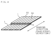
- FIG. 4 is a perspective view that conceptually shows a state in which a shadow S is formed on the solar electric power apparatus of the first embodiment
- FIG. 5 is a perspective view that conceptually shows a state in which a shadow S is formed on a solar electric power apparatus of a comparative example.
- the serial connecting direction of the solar cells 20 is set to a direction parallel to the ranging direction in which the solar modules 1 are ranged in a stepped manner.
- a shadow S of the solar module 1 on the upper side is formed on one portion of the solar module 1 on the lower side.
- the shadow S is formed on the upper side.
- the solar electric power apparatus of the first embodiment as shown in FIG. 4, the upper side of each solar cell 20 is covered with the shadow S to virtually the same degree. Therefore, a plurality of solar cells 20 that have a reduction in the output to the same degree are electrically connected in series with each other. In this manner, in the solar electric power apparatus of the first embodiment, even when a shadow S is formed, the solar cells 20 having virtually the same output are series-connected; therefore, no problems arise.
- the solar cell 20 on the uppermost side is virtually completely covered with a shadow S, with the result that hardly any current is generated in this solar cell 20.
- the solar cells 20 on the lower side are free from the shadow S, with the result that there is no reduction in the outputs. Therefore, in the solar electric power apparatus of the comparative example, the solar cells 20, each of which generates an output that is the same output as designed, are series-connected to the solar cell 20 that generates hardly any current, raising a problem in which no output is obtained as the module.
- a reverse bias voltage is applied from other solar cells 20 to the solar cell 20 covered with the shadow S, there is a possibility that the solar cell 20 in question might be damaged.
- FIG. 6A shows a sheet of a solar module 1 in the solar electric power apparatus of the first embodiment, in which 40 solar cells 20 are connected in a direction orthogonal to the ranging direction.
- FIG. 7A shows a sheet of a solar module 1 in the solar electric power apparatus of the comparative example, in which 40 solar cells 20 are connected in a direction parallel to the ranging direction. Supposing that a shadow S is formed on an area covering 10 % of the surface of the solar module 1, in the case of the example (first embodiment) of FIG. 6A, 10% of each of the forty solar cells 20 is shielded from light, and in the case of the example (comparative example) of FIG. 7A, four solar cells that account for 10 % of the forty solar cells 20 are completely shielded from light.
- FIG. 6B and FIG. 7B are graphs that show output characteristics (the relationship between the output voltage (V) and the output current (A)) of the solar modules 1 shown in FIG. 6A and FIG. 7A.
- solid line B represents an output characteristic with no shadow S being formed
- solid line C represents an output characteristic with a shadow S being formed.
- the output (electric power) has only a reduction of approximately 10 %
- the comparative example (FIG. 7B) the output (electric power) has a reduction as much as approximately 50 %.
- the solar electric power apparatus is provided with a plurality of solar modules 1 that are ranged in a stepped manner, each solar module 1 having a plurality of solar cells 20 that are constituted by amorphous semiconductors, and electrically connected in series with each other, and the serial connecting direction of the solar cells 20 is set to a direction orthogonal to the ranging direction of the solar modules 1; therefore, even when a shadow S of the solar module 1 on the upper side is formed on the solar module 1 on the lower side, no problems arise, thereby making it possible to provide a solar electric power apparatus having superior output characteristics.
- FIG. 8 is a cross-sectional view showing the structure of a solar module 1 in accordance with the second embodiment.
- the solar module 1 (thickness: b (mm)) comprises a transparent substrate 10 made of, for example, glass, a plurality of solar cells 20 having a photoelectric conversion function, connected in series with each other, and a back surface material 3 made of, for example, a resin film, which are laminated with each other; and on its one side portion, no solar cells 20 are installed over a length L(mm) from the end face, that is, a laminated structure, constituted only by the transparent substrate 10 and the back surface material 3, is formed, thereby providing an area where no power is generated (non-power generation area).
- FIG. 9 is a cross-sectional view that shows a state in which these solar modules 1 are ranged on a roof 100 in a stepped manner in the eave-ridge direction (the ranging direction).
- Each of these solar modules 1 is installed in a manner so as to place its non-power generation area on the upper side (ridge side), and the adjacent solar modules 1 are arranged on the roof 100 in a stepped manner from the ridge side toward the eaves side with a step difference of b, with the edges thereof being overlapped on each other.
- the serial connecting direction of the solar cells 20 is set to a direction parallel to the ranging direction (ridge-eave direction) in which the solar modules 1 are ranged in a stepped manner.
- a shadow S (a hatched portion in FIG. 9, length: a (mm)) of the solar module 1 on the upper side is formed on the solar module 1 on the lower side.
- a non-power generation area having a length of L
- the shadow S is formed on the portion corresponding to this non-power generation area. Therefore, different from the conventional arrangement, no adverse effects are given by the shadow S so that the portion bearing the shadow S does not form a great resistance; thus, it is possible to prevent a reduction in the output of the solar module 1, and consequently to provide a stable photoelectric power.
- the non-power generation area is preferably placed only within an area in which the shadow S is positively formed, and the optimum value of the length L is set so as to allow the amount of annual power generation obtained by the solar module 1 of the second embodiment to exceed the amount of annual power generation obtained by a conventional solar module 1.
- This optimum value is related to the installation conditions of the solar module 1, the altitude of the sun, etc.
- the length a of the shadow S formed upon application of sunlight from the ridge side depends on the angle and orientation at the time when the solar modules 1 are installed, the altitude of the sun, the orientation of the sun, etc.
- the solar modules 1 are placed with a tilt angle in a range of approximately 20 to 30° (installation angle) on the east side, south side, west side, or a side in between on a roof. Therefore, in actual service, under the condition of a sun latitude in the range of 30 to 40° where the intensity of sunlight is strong and the sun latitude exceeds the tilt angle (installation angle) of the solar modules 1, provision is made so as to prevent the shadow S from giving adverse effects to the solar modules 1.
- the length a of the shadow S is maintained 0. 98 to 5. 7 times the step difference b (the thickness of the solar module 1) all through the year. Moreover, when the same calculations are made by using the altitude of the sun of 40°, the length a of the shadow S is maintained 0. 48 to 2. 7 times the step difference b (the thickness of the solar module 1).
- the length L of the non-power generation area that is formed in one side portion of the solar module 1 is preferably set in the range from 0. 5 to 6 times the step difference b (the thickness of the solar module 1) so as to be coincident with the length a of the shadow S that is formed thereon.
- the solar cells 20 are placed approximately 10 mm apart from the side edge. Therefore, the above-mentioned length L is preferably set in the range from not less than 10 mm to not more than 6b (mm).
- the step difference b (the thickness of the solar module 1) to not less than 20 mm from the designing point of view.
- the step difference b the thickness of the solar module 1
- the upper limit value becomes 120 mm, thereby reducing the power generating area to a great degree.
- the upper limit of the length L is set to three times the step difference b (the thickness of the solar module 1).
- the length L is preferably set in the range from not less than 10 mm to not more than 3b(mm).
- the non-power generation area is provided in one side portion located on the upper solar module 1 side when placed in a stepped manner; therefore, different from the conventional arrangement, no adverse effects are given from the shadow S; therefore, it is possible to prevent a reduction in the output of the solar module 1, and consequently to obtain a stable photoelectric power.
- the length of the non-power generation area is set to not more than six times the thickness of the solar module 1, or, in the case of the thickness of the solar module 1 of not less than 20 mm, it is set to not more than three times the thickness; therefore, it is possible to completely prevent adverse effects of the shadow S without causing a great reduction in the amount of power generation.
- FIG. 11 is a cross-sectional view that shows a stepped installation state of a plurality of solar modules 1 in accordance with the third embodiment.
- the same members as FIG. 9 are indicated by the same reference numbers, and the description thereof is omitted.
- normal solar modules 1 without the non-power generation area are ranged in a stepped manner from the ridge side to the eaves side on a roof 100, with an interposition object 30 having a length of L, made of glass, resin, etc., being interpolated between the adjacent solar modules 1.
- the serial connecting direction of the solar cells 20 is set to a direction parallel to the ranging direction (eave-ridge direction).
- a shadow S (a hatched portion in FIG. 11) of the solar module 1 on the upper side is formed on the interposition object 30; therefore, in the same manner as the second embodiment, no adverse effects are given from the shadow S; therefore, it is possible to prevent a reduction in the output of the solar module 1, and consequently to obtain a stable photoelectric power.
- the length L of the interposition object 30 can be set in the same manner as the length L of the non-power generation area in the second embodiment.
- solar modules 1 are placed in a stepped manner with the interposition object 30 that is not related to power generation being interpolated between the adjacent solar modules 1; therefore, different from the conventional arrangement, no adverse effects are given from the shadow S; thus, it is possible to prevent a reduction in the output of the solar module 1, and consequently to obtain a stable photoelectric power.
- the second and third embodiments become more effective when a solar battery of an integrated type is used and when the solar modules 1 are ranged with the serial connecting direction of a plurality of solar cells 20 being set to a direction parallel to the ranging direction (ridge-eave direction).
- the present invention is not intended to be limited thereby, and the present invention may be applied to a case where they are attached to, for example, a side face of a building, etc.
- the present invention may be applied to any solar electric power apparatus having solar modules ranged in such a manner that edges of adjacent solar modules are overlapped.
Abstract
Description
Claims (21)
- A solar electric power apparatus which comprises a plurality of solar modules (1) that are ranged in such a manner that edges of adjacent solar modules are overlapped, characterized by that said solar module (1) comprises a plurality of solar cells (20) which are electrically connected in series with each other, and that the serial connecting direction of said plurality of solar cells (20) is set to a direction orthogonal to the ranging direction of said plurality of solar modules (1).
- A solar electric power apparatus which comprises a plurality of solar modules (1) that are ranged in such a manner that edges of adjacent solar modules are overlapped, characterized by that said solar module (1) comprises a plurality of solar cells (20) which are electrically connected in series with each other in a direction parallel to the ranging direction of said plurality of solar modules (1), and that said solar module (1) is provided with a non-power generation area on one side portion thereof in the range direction.
- The solar electric power apparatus according to claim 2, wherein said non-power generation area has a length (L) of not less than 10 mm and not more than 6 times a thickness (b) of said solar module (1).
- The solar electric power apparatus according to claim 2, wherein, when said solar module (1) has a thickness (b) of not less than 20 mm, said non-power generation area has a length (L) of not less than 10 mm and not more than three times a thickness (b) of said solar module (1).
- The solar electric power apparatus according to one of claims 2 to 4, wherein said non-power generation area is formed by removing the solar cells (20).
- The solar electric power apparatus according to one of claims 2 to 4, wherein said non-power generation area is formed by an interposition object (30) that is not related to power generation.
- The solar electric power apparatus according to one of claims 1 to 6, wherein said plurality of solar cells (20) are series-connected on a common substrate (10).
- The solar electric power apparatus according to one of claims 1 to 7, wherein said solar cell (20) includes an amorphous semiconductor.
- The solar electric power apparatus according to one of claims 1 to 8, wherein the ranging direction is an eave-ridge direction of a roof.
- A solar module (1), a plurality of which are to be ranged in such a manner that edges of adjacent solar modules (1) are overlapped so as to constitute a solar electric power apparatus, characterized by comprising:a plurality of solar cells (20) that are series-connected in a direction orthogonal to the ranging direction of the solar modules (1).
- A solar module (1), a plurality of which are to be ranged in such a manner that edges of adjacent solar modules (1) are overlapped so as to constitute a solar electric power apparatus, characterized by comprising:a plurality of solar cells (20) that are series-connected in a direction parallel to the ranging direction of the solar modules (1); anda non-power generation area formed on one side portion thereof in the ranging direction.
- The solar module (1) according to claim 11, wherein said non-power generation area has a length (L) of not less than 10 mm and not more than 6 times a thickness (b) of said solar module (1).
- The solar module (1) according to claim 11, wherein, when said solar module (1) has a thickness (b) of not less than 20 mm, said non-power generation area has a length (L) of not less than 10 mm and not more than three times the thickness (b).
- The solar module (1) according to one of claims 11 to 13, wherein said non-power generation area is formed by removing the solar cells (20).
- The solar module (1) according to one of claims 10 to 14, wherein said plurality of solar cells (20) are series-connected on a common substrate (10).
- The solar module (1) according to one of claims 10 to 15, wherein said solar cell (20) includes an amorphous semiconductor.
- The solar module (1) according to one of claims 10 to 16, wherein the ranging direction is an eave-ridge direction of a roof.
- An installation method of solar modules (1), characterized by comprising the steps of:preparing a plurality of solar modules (1), each of which has a plurality of solar cells (20) that are series-connected on a common substrate (10); andranging said plurality of solar modules (1) in a direction orthogonal to the serial connecting direction of said plurality of solar cells (20).
- An installation method of solar modules (1). characterized by comprising the steps of:preparing a plurality of solar modules (1), each of which has a non-power generation area on a side portion thereof and a plurality of solar cells (20) that are series-connected on a common substrate (10); andranging said plurality of solar modules (1).
- An installation method of solar modules (1), characterized by comprising the steps of:preparing a plurality of solar modules (1), each of which has a plurality of solar cells (20) that are series-connected on a common substrate (10); andranging said plurality of solar modules (1) with an interpolation object (30) not related to power generation being interpolated between adjacent solar modules (1, 1).
- The installation method of solar modules (1) according to one of claims 18 to 20, wherein the ranging direction of said plurality of solar modules (1) is an eave-ridge direction of a roof.
Applications Claiming Priority (4)
| Application Number | Priority Date | Filing Date | Title |
|---|---|---|---|
| JP11209421A JP2001036125A (en) | 1999-07-23 | 1999-07-23 | Photovoltaic power generation device |
| JP20942199 | 1999-07-23 | ||
| JP26085199 | 1999-09-14 | ||
| JP26085199A JP2001081917A (en) | 1999-09-14 | 1999-09-14 | Solar cell module and installation method therefor |
Publications (3)
| Publication Number | Publication Date |
|---|---|
| EP1071136A2 true EP1071136A2 (en) | 2001-01-24 |
| EP1071136A3 EP1071136A3 (en) | 2005-01-12 |
| EP1071136B1 EP1071136B1 (en) | 2006-12-13 |
Family
ID=26517438
Family Applications (1)
| Application Number | Title | Priority Date | Filing Date |
|---|---|---|---|
| EP00115553A Expired - Lifetime EP1071136B1 (en) | 1999-07-23 | 2000-07-19 | Solar electric power apparatus, solar module, and installation method of solar modules |
Country Status (4)
| Country | Link |
|---|---|
| US (1) | US6342669B1 (en) |
| EP (1) | EP1071136B1 (en) |
| DE (1) | DE60032292T2 (en) |
| ES (1) | ES2278564T3 (en) |
Cited By (3)
| Publication number | Priority date | Publication date | Assignee | Title |
|---|---|---|---|---|
| US8413391B2 (en) | 2008-10-13 | 2013-04-09 | Sunlink Corporation | Solar array mounting system with universal clamp |
| US9038329B2 (en) | 2011-10-11 | 2015-05-26 | Sunlink Corporation | Structure following roof mounted photovoltaic system |
| US9279415B1 (en) | 2005-07-07 | 2016-03-08 | Sunlink Corporation | Solar array integration system and methods therefor |
Families Citing this family (20)
| Publication number | Priority date | Publication date | Assignee | Title |
|---|---|---|---|---|
| US20090293941A1 (en) * | 2008-06-02 | 2009-12-03 | Daniel Luch | Photovoltaic power farm structure and installation |
| US20100108118A1 (en) * | 2008-06-02 | 2010-05-06 | Daniel Luch | Photovoltaic power farm structure and installation |
| US8664030B2 (en) | 1999-03-30 | 2014-03-04 | Daniel Luch | Collector grid and interconnect structures for photovoltaic arrays and modules |
| US6875914B2 (en) * | 2002-01-14 | 2005-04-05 | United Solar Systems Corporation | Photovoltaic roofing structure |
| JP2004006702A (en) * | 2002-03-28 | 2004-01-08 | Canon Inc | Solar cell module placement structure, solar cell module array, and solar energy power generation system |
| US7297866B2 (en) * | 2004-03-15 | 2007-11-20 | Sunpower Corporation | Ventilated photovoltaic module frame |
| US9236512B2 (en) | 2006-04-13 | 2016-01-12 | Daniel Luch | Collector grid and interconnect structures for photovoltaic arrays and modules |
| US9865758B2 (en) | 2006-04-13 | 2018-01-09 | Daniel Luch | Collector grid and interconnect structures for photovoltaic arrays and modules |
| US9006563B2 (en) | 2006-04-13 | 2015-04-14 | Solannex, Inc. | Collector grid and interconnect structures for photovoltaic arrays and modules |
| US8884155B2 (en) | 2006-04-13 | 2014-11-11 | Daniel Luch | Collector grid and interconnect structures for photovoltaic arrays and modules |
| US8822810B2 (en) | 2006-04-13 | 2014-09-02 | Daniel Luch | Collector grid and interconnect structures for photovoltaic arrays and modules |
| US8729385B2 (en) | 2006-04-13 | 2014-05-20 | Daniel Luch | Collector grid and interconnect structures for photovoltaic arrays and modules |
| PT2208238E (en) * | 2007-11-09 | 2013-07-10 | Sunpreme Inc | Low-cost solar cells and methods for their production |
| EP2248186A2 (en) * | 2008-02-19 | 2010-11-10 | CertainTeed Corporation | Structured photovoltaic roofing elements, systems and kits |
| US7951640B2 (en) * | 2008-11-07 | 2011-05-31 | Sunpreme, Ltd. | Low-cost multi-junction solar cells and methods for their production |
| US8796066B2 (en) | 2008-11-07 | 2014-08-05 | Sunpreme, Inc. | Low-cost solar cells and methods for fabricating low cost substrates for solar cells |
| JP5385890B2 (en) * | 2010-12-22 | 2014-01-08 | 東レエンジニアリング株式会社 | Solar cell module and manufacturing method thereof |
| US9634168B2 (en) * | 2011-08-04 | 2017-04-25 | Beijing Apollo Ding Rong Solar Technology Co., Ltd. | Attachment structures for building integrable photovoltaic modules |
| JP5583093B2 (en) * | 2011-09-21 | 2014-09-03 | シャープ株式会社 | Photovoltaic module and photovoltaic module array |
| JP6905936B2 (en) | 2015-11-13 | 2021-07-21 | 株式会社カネカ | Installation structure of solar cell module, solar cell module, and installation method of solar cell module |
Citations (5)
| Publication number | Priority date | Publication date | Assignee | Title |
|---|---|---|---|---|
| EP0535614A2 (en) * | 1991-09-30 | 1993-04-07 | Sharp Kabushiki Kaisha | Solar battery module |
| US5437735A (en) * | 1993-12-30 | 1995-08-01 | United Solar Systems Corporation | Photovoltaic shingle system |
| US5542989A (en) * | 1994-01-28 | 1996-08-06 | Fuji Electric Co., Ltd. | Solar battery roofing for a solar house |
| WO1998013883A1 (en) * | 1996-09-23 | 1998-04-02 | Atlantis Solar Systeme Ag | Photovoltaic solar roof |
| US5986203A (en) * | 1996-06-27 | 1999-11-16 | Evergreen Solar, Inc. | Solar cell roof tile and method of forming same |
Family Cites Families (1)
| Publication number | Priority date | Publication date | Assignee | Title |
|---|---|---|---|---|
| JPH114010A (en) * | 1997-06-13 | 1999-01-06 | Canon Inc | Manufacturing method and installation method of solar battery module |
-
2000
- 2000-07-19 EP EP00115553A patent/EP1071136B1/en not_active Expired - Lifetime
- 2000-07-19 ES ES00115553T patent/ES2278564T3/en not_active Expired - Lifetime
- 2000-07-19 DE DE60032292T patent/DE60032292T2/en not_active Expired - Lifetime
- 2000-07-20 US US09/620,733 patent/US6342669B1/en not_active Expired - Lifetime
Patent Citations (5)
| Publication number | Priority date | Publication date | Assignee | Title |
|---|---|---|---|---|
| EP0535614A2 (en) * | 1991-09-30 | 1993-04-07 | Sharp Kabushiki Kaisha | Solar battery module |
| US5437735A (en) * | 1993-12-30 | 1995-08-01 | United Solar Systems Corporation | Photovoltaic shingle system |
| US5542989A (en) * | 1994-01-28 | 1996-08-06 | Fuji Electric Co., Ltd. | Solar battery roofing for a solar house |
| US5986203A (en) * | 1996-06-27 | 1999-11-16 | Evergreen Solar, Inc. | Solar cell roof tile and method of forming same |
| WO1998013883A1 (en) * | 1996-09-23 | 1998-04-02 | Atlantis Solar Systeme Ag | Photovoltaic solar roof |
Cited By (4)
| Publication number | Priority date | Publication date | Assignee | Title |
|---|---|---|---|---|
| US9279415B1 (en) | 2005-07-07 | 2016-03-08 | Sunlink Corporation | Solar array integration system and methods therefor |
| US8413391B2 (en) | 2008-10-13 | 2013-04-09 | Sunlink Corporation | Solar array mounting system with universal clamp |
| US9601645B2 (en) | 2008-10-13 | 2017-03-21 | Sunlink Corporation | Solar array mounting system with universal clamp |
| US9038329B2 (en) | 2011-10-11 | 2015-05-26 | Sunlink Corporation | Structure following roof mounted photovoltaic system |
Also Published As
| Publication number | Publication date |
|---|---|
| DE60032292T2 (en) | 2007-07-12 |
| DE60032292D1 (en) | 2007-01-25 |
| US6342669B1 (en) | 2002-01-29 |
| ES2278564T3 (en) | 2007-08-16 |
| EP1071136B1 (en) | 2006-12-13 |
| EP1071136A3 (en) | 2005-01-12 |
Similar Documents
| Publication | Publication Date | Title |
|---|---|---|
| EP1071136B1 (en) | Solar electric power apparatus, solar module, and installation method of solar modules | |
| US5849107A (en) | Solar battery module and passive solar system using same | |
| US20120167942A1 (en) | Low-concentration flat profile photovoltaic modules | |
| US20040112424A1 (en) | Solar cell assembly, and photovoltaic solar electric generator of concentrator type | |
| JP3239035B2 (en) | Solar cell module with snow melting function and solar power generation system with snow melting function | |
| US20050081908A1 (en) | Method and apparatus for generation of electrical power from solar energy | |
| US20030029497A1 (en) | Solar energy converter using optical concentration through a liquid | |
| US20050126622A1 (en) | Solar cell module and method of producing the same | |
| JP2001148500A (en) | Solar cell module | |
| JPH0685305A (en) | Solar cell module integrated with roof material | |
| US11424714B2 (en) | Angled polymer solar modules | |
| US20180366606A1 (en) | Solar cell module | |
| US20110174365A1 (en) | System and method for forming roofing solar panels | |
| JP3985837B2 (en) | Photovoltaic power generation apparatus and installation method thereof | |
| JP3818651B2 (en) | Solar power system | |
| JP4208419B2 (en) | Solar cell module | |
| JPH09210472A (en) | Solar energy collection panel and passive solar system | |
| JPH1019388A (en) | Hybrid type panel and building equipped with this hybrid type panel | |
| JP3794245B2 (en) | Solar power plant | |
| JP2760599B2 (en) | Roof-mounted solar cells | |
| JPH10270740A (en) | Light collecting structure of solar battery | |
| US20120073627A1 (en) | Solar cell module | |
| JP2002190611A (en) | Power generator proded with a plurality of solar battery modules | |
| JP2007180065A (en) | Solar battery array | |
| JP2001036125A (en) | Photovoltaic power generation device |
Legal Events
| Date | Code | Title | Description |
|---|---|---|---|
| PUAI | Public reference made under article 153(3) epc to a published international application that has entered the european phase |
Free format text: ORIGINAL CODE: 0009012 |
|
| AK | Designated contracting states |
Kind code of ref document: A2 Designated state(s): AT BE CH CY DE DK ES FI FR GB GR IE IT LI LU MC NL PT SE |
|
| AX | Request for extension of the european patent |
Free format text: AL;LT;LV;MK;RO;SI |
|
| PUAL | Search report despatched |
Free format text: ORIGINAL CODE: 0009013 |
|
| AK | Designated contracting states |
Kind code of ref document: A3 Designated state(s): AT BE CH CY DE DK ES FI FR GB GR IE IT LI LU MC NL PT SE |
|
| AX | Request for extension of the european patent |
Extension state: AL LT LV MK RO SI |
|
| 17P | Request for examination filed |
Effective date: 20050120 |
|
| AKX | Designation fees paid |
Designated state(s): DE ES FR IT |
|
| GRAP | Despatch of communication of intention to grant a patent |
Free format text: ORIGINAL CODE: EPIDOSNIGR1 |
|
| GRAS | Grant fee paid |
Free format text: ORIGINAL CODE: EPIDOSNIGR3 |
|
| GRAA | (expected) grant |
Free format text: ORIGINAL CODE: 0009210 |
|
| AK | Designated contracting states |
Kind code of ref document: B1 Designated state(s): DE ES FR IT |
|
| REF | Corresponds to: |
Ref document number: 60032292 Country of ref document: DE Date of ref document: 20070125 Kind code of ref document: P |
|
| ET | Fr: translation filed | ||
| REG | Reference to a national code |
Ref country code: ES Ref legal event code: FG2A Ref document number: 2278564 Country of ref document: ES Kind code of ref document: T3 |
|
| PLBE | No opposition filed within time limit |
Free format text: ORIGINAL CODE: 0009261 |
|
| STAA | Information on the status of an ep patent application or granted ep patent |
Free format text: STATUS: NO OPPOSITION FILED WITHIN TIME LIMIT |
|
| 26N | No opposition filed |
Effective date: 20070914 |
|
| REG | Reference to a national code |
Ref country code: FR Ref legal event code: PLFP Year of fee payment: 17 |
|
| REG | Reference to a national code |
Ref country code: FR Ref legal event code: PLFP Year of fee payment: 18 |
|
| REG | Reference to a national code |
Ref country code: FR Ref legal event code: PLFP Year of fee payment: 19 |
|
| PGFP | Annual fee paid to national office [announced via postgrant information from national office to epo] |
Ref country code: FR Payment date: 20190619 Year of fee payment: 20 |
|
| PGFP | Annual fee paid to national office [announced via postgrant information from national office to epo] |
Ref country code: ES Payment date: 20190802 Year of fee payment: 20 Ref country code: IT Payment date: 20190719 Year of fee payment: 20 Ref country code: DE Payment date: 20190710 Year of fee payment: 20 |
|
| REG | Reference to a national code |
Ref country code: DE Ref legal event code: R071 Ref document number: 60032292 Country of ref document: DE |
|
| REG | Reference to a national code |
Ref country code: ES Ref legal event code: FD2A Effective date: 20201026 |
|
| PG25 | Lapsed in a contracting state [announced via postgrant information from national office to epo] |
Ref country code: ES Free format text: LAPSE BECAUSE OF EXPIRATION OF PROTECTION Effective date: 20200720 |