EP1071085A2 - Device for securing optical element - Google Patents
Device for securing optical element Download PDFInfo
- Publication number
- EP1071085A2 EP1071085A2 EP00115500A EP00115500A EP1071085A2 EP 1071085 A2 EP1071085 A2 EP 1071085A2 EP 00115500 A EP00115500 A EP 00115500A EP 00115500 A EP00115500 A EP 00115500A EP 1071085 A2 EP1071085 A2 EP 1071085A2
- Authority
- EP
- European Patent Office
- Prior art keywords
- optical element
- base
- mounting surface
- optical
- mounting
- Prior art date
- Legal status (The legal status is an assumption and is not a legal conclusion. Google has not performed a legal analysis and makes no representation as to the accuracy of the status listed.)
- Withdrawn
Links
Images

Classifications
-
- G—PHYSICS
- G11—INFORMATION STORAGE
- G11B—INFORMATION STORAGE BASED ON RELATIVE MOVEMENT BETWEEN RECORD CARRIER AND TRANSDUCER
- G11B7/00—Recording or reproducing by optical means, e.g. recording using a thermal beam of optical radiation by modifying optical properties or the physical structure, reproducing using an optical beam at lower power by sensing optical properties; Record carriers therefor
- G11B7/12—Heads, e.g. forming of the optical beam spot or modulation of the optical beam
- G11B7/22—Apparatus or processes for the manufacture of optical heads, e.g. assembly
-
- G—PHYSICS
- G02—OPTICS
- G02B—OPTICAL ELEMENTS, SYSTEMS OR APPARATUS
- G02B7/00—Mountings, adjusting means, or light-tight connections, for optical elements
Definitions
- the present invention relates to a device for securing an optical element, such as a beam splitter, installed in an optical pick-up device, and, more particularly, to a device for securing an optical element to a securing section in an optical pick-up device with high precision.
- an optical element such as a beam splitter
- Fig. 4 schematically illustrates the internal structure of a conventional optical pick-up device.
- Fig. 5 is a sectional view of the inside of a base (that is, a carriage), in which the conventional optical element is secured.
- the conventional optical pick-up device comprises a laser diode 1 which emits a laser beam, an optical element 2, a reflecting mirror 3, an objective lens 4, and a light detector 5. These component parts are installed on a base (not shown) of the optical pick-up device in the positional relationship shown in Fig. 4.
- the laser beam irradiated from the laser diode 1 is incident on a side surface (that is, an incident surface) 2a of the optical element 2 at a predetermined angle of incidence.
- the optical element 2 may be, for example, a polarization beam splitter or a half mirror which can divide the incident light beam into two types of light beams, that is, a reflected light beam and a transmitted light beam.
- a portion of the light beam is reflected by the side surface 2a of the optical element 2 towards the reflecting mirror 3.
- the objective lens 4 is disposed above the reflecting mirror 3.
- the reflecting mirror 3 is inclined by a predetermined angle in the optical pick-up device in order to guide the reflected laser beam to the objective lens 4.
- a disk (not shown), such as a compact disk (CD) or a digital video disk (DVD), is mounted above the objective lens 4.
- the objective lens 4 is capable of focusing the light beam reflected by the reflecting mirror 3 onto a signal-recording surface of the disk and making it fall upon the signal-recording surface.
- the returning light beam reflected from the signal-recording surface of the disk travels back to the optical element 2 by passing through the same path taken to reach the objective lens 4 in the opposite direction. Some of the returning light beam passes through the optical element 2, and is guided to the light detector 5 disposed behind the optical element 2.
- the light detector 5 is, for example, a pin photodiode, and detects the returning light beam that has passed through the optical element 2 in order to perform various signal processing operations thereon.
- the side surface 2a of the optical element 2 is an incident surface of the light beam from the laser diode 1 and a reflection surface which directs the light beam to the objective lens 4. Therefore, any tilting of the side surface 2a of the optical element 2 affects, for example, a reading operation of a signal from the disk.
- the optical element 2 when the optical element 2 is not precisely positioned at a predetermined location in the base of the optical pick-up device, that is, when the side surface 2a is not oriented with high precision in a direction a1 where the laser diode 1 is disposed and in a direction b1 where the reflecting mirror 3 is disposed, the center of the laser beam get shifted from an optical axis O 1 of the objective lens 4, causing aberrations to increase, so that, for example, the shape of the laser beam spot formed on the signal-recording surface of the disk gets distorted.
- the base 6 is formed by die-casting a metal, such as aluminum or magnesium.
- a metal such as aluminum or magnesium.
- a mold must be removed from the base 6 in a direction perpendicular to the bottom surface 6a of the base 6 (that is, in a direction parallel to the mounting surface 7b).
- the mounting surface 7b is parallel to the direction in which the mold is removed, the mounting surface 7b and the mold rub against each other when the mold is removed, resulting in problems such as scratching and distortion of the mounting surface 7b.
- an object of the present invention to provide a device for securing an optical element capable of preventing rubbing occurring as a result of mold releasing, and allowing a surface for positioning the optical element with high precision to be formed when a molding operation is completed.
- a device for securing an optical element in which a base includes a mounting surface formed substantially perpendicular to a surface of the base, and an optical element with a reference optical surface serving as a light-reflecting surface, a light-incident surface, or a light-exiting surface is positioned by bringing the reference optical surface and the mounting surface into intimate contact with each other, wherein:
- the very small angle ⁇ 1 may be greater than 0 degrees and equal to or less than 3 degrees.
- the mounting surface in the securing section of the base into an inclined surface
- the mounting surface of the base and the inclined molding surface of the mold can be properly separated from each other, so that, when a molding operation is completed, the mounting surface can be formed smoothly with high precision. Therefore, the mounting surface in a molded state can serve as a reference surface for securing the optical element, making it unnecessary to perform a mechanical cutting operation on the mounting surface after the removal of the base from the mold.
- a base includes a mounting surface formed substantially perpendicular to a surface of the base, and an optical element with a reference optical surface serving as a light-reflecting surface, a light-incident surface, or a light-exiting surface is positioned by bringing the reference optical surface and the mounting surface into intimate contact with each other, and in which the mounting surface is formed at an angle of 90 degrees plus a very small angle ⁇ 1 with respect to the surface of the base, the base may include a bottom portion mounting surface formed at right angles to the mounting surface, the optical element may include a bottom surface formed at right angles to the reference optical surface, and the optical element may be positioned by bringing the reference optical surface into intimate contact with the mounting surface and by abutting the bottom surface against the bottom portion mounting surface.
- the optical element By maintaining the mounting surface and the bottom portion mounting surface at right angles to each other, the optical element can be secured to the mounting surface with high precision.
- the optical element can be secured in the securing section with high precision by setting the angle between the mounting surface and the bottom surface of the securing section at 90 degrees.
- a device for securing an optical element in which a base includes a mounting surface formed substantially perpendicular to a surface of the base, and an optical element with a reference optical surface serving as a light-reflecting surface, a light-incident surface, or a light-exiting surface is positioned by bringing the reference optical surface and the mounting surface into intimate contact with each other, and in which the mounting surface is formed at an angle of 90 degrees plus a very small angle ⁇ 1 with respect to the surface of the base, the optical element may be supported in a cantilever manner by bringing one end of the reference optical surface extending in a widthwise direction along the surface of the base into intimate contact with the mounting surface, while an optical axis crossing an area of the reference optical surface is not brought into intimate contact with the mounting surface.
- this structure can prevent problems produced when both ends of the optical element are secured, such as dimensional differences between the mounting surfaces to which both ends of the optical element are secured. Therefore, the problem of the optical element becoming deformed when both ends of the reference optical surface of the optical element are forcibly secured to the mounting surfaces due to the dimensional differences between the mounting surfaces can be prevented from occurring. Consequently, it is possible to orient with high precision the optical axis which crosses (or is incident on, is reflected by, or passes through) the reference optical surface (that is, the incident surface) of the optical element.
- a base includes a mounting surface formed substantially perpendicular to a surface of the base, and an optical element with a reference optical surface serving as a light-reflecting surface, a light-incident surface, or a light-exiting surface is positioned by bringing the reference optical surface and the mounting surface into intimate contact with each other, and in which the mounting surface is formed at an angle of 90 degrees plus a very small angle ⁇ 1 with respect to the surface of the base, the base may be molded of a metallic material, and the mounting surface may be mechanically processed.
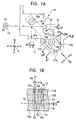
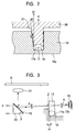
- Figs. 1A and 1B each illustrate a portion of a base (that is, a carriage) of an optical pick-up device. More specifically, Fig. 1A is a plan view primarily showing a securing section, and Fig. 1B is a sectional view taken along line B-B of Fig. 1A. Fig. 2 is a sectional view taken along line II-II of Fig. 1A, showing the relationship between the securing section and a mold. Fig. 3 is a side view showing the relationship between an optical element and a reflecting mirror in the base.
- An optical pick-up device for recording data onto and reading data from a disk is installed in various disk devices, such as a compact disk (CD) player, a digital video disk (DVD) player, or a mini-disk (MD) player.
- the optical pick-up device is disposed so as to be movable with respect to a disk on a turntable in a radial direction thereof.
- a base 16 serves as a supporting base member, and a light-emitting element (that is, a laser diode) 11, an optical element 12, a reflecting mirror 13, an objective lens 14, and a light detector 15 are mounted on the base 16.
- a light-emitting element that is, a laser diode
- an optical element 12 a reflecting mirror 13
- an objective lens 14 a light detector 15
- a securing section 17 which is a recess-shaped area in cross-section is formed in the base 16.
- the optical element 12 such as a half mirror or a polarization beam splitter, is provided in the securing section 17.
- Protruding cylindrical pedestals 18 and 19 are formed on a bottom surface (that is, a bottom portion mounting surface) 17c in the securing section 17.
- Through holes 18a and 19a are formed in the centers of the corresponding pedestals 18 and 19.
- Mounting surfaces 17a and 17b are formed adjacent to a side of the pedestal 18 in the direction of arrow R illustrated in Fig. 1A.
- the mounting surfaces 17a and 17b are both formed substantially perpendicular to the bottom surface 17c.
- angles from the bottom portion mounting surface 17c are each equal to 90 degrees plus the very small angle ⁇ 1, and ⁇ 1 is preferably greater than 0 degrees and less than or equal to 3 degrees (that is, 0 ⁇ ⁇ 1 ⁇ 3 degrees).
- an inclination angle ⁇ 2 of each of the pedestals 18 and 19 from a horizontal axis is equal to its corresponding small angle ⁇ 1. Therefore, the angle between the mounting surface 17a and a surface (that is, a bottom portion mounting surface) of the pedestal 18, and the angle between the mounting surface 17b and a surface (that is, a bottom portion mounting surface) of the pedestal 19, are 90 degrees. In other words, the angles between lines extending at the corresponding very small angles ⁇ 1 and corresponding lines extending at the corresponding inclination angles ⁇ 2 are 90 degrees.
- the light-emitting element 11, such as a laser diode, the reflecting mirror 13, the objective lens 14, and the light detector 15 are disposed at predetermined locations around the optical element 12 in the base 16. More specifically, in Fig. 1A, the light-emitting element 11 is disposed at a location a2 in the direction of arrow Y1 from the optical element 12, and the reflecting mirror 13 is disposed at a location b2 in the direction of arrow X2 in Fig. 1A.
- the light detector 15 is disposed at a location c2 in the direction of arrow X1 in Fig. 1A.
- the base (or carriage) 16 of the optical pick-up device is formed by die-casting, for example, an alloy of aluminum. More specifically, it is formed by pouring molten aluminum into a mold (not shown), cooling it, and, then, removing the mold from the base 16.
- a bottom surface 16a of the base 16 is set perpendicular to a perpendicular axis (that is, the Z axis).
- the direction of arrow F in which a mold 30 is removed and a vertical direction Z1 are the same.
- an opposing surface (an inclined mold surface) 31 of the mold 30 opposing the mounting surfaces 17a and 17b at an angle equal to 90 degrees plus the very small angle ⁇ 1 (formed from the vertical axis or the Z axis) the mounting surfaces 17a and 17b of the base 16 can be formed at the angle equal to 90 degrees plus the very small angle ⁇ 1.
- the opposing surface 31 of the mold 30 and the mounting surfaces 17a and 17b of the securing section 17 of the base 16 oppose each other at the angle equal to 90 degrees plus the very small angle ⁇ 1. Therefore, by removing the mold 30 in the vertical direction Z1, it is possible to improve how well the mounting surfaces 17a and 17b of the securing section 17 and the opposing surface 31 of the mold 30 are separated from each other, so that, when the mold is released, the mounting surfaces 17a and 17b do not get scratched or distorted. Since, in the molding state, the mounting surfaces 17a and 17b can be smoothly formed, they can be formed as reference surfaces for positioning the optical element 12 in the securing section 17 without subjecting the mounting surfaces 17a and 17b to a cutting operation.
- the mounting surfaces 17a and 17b can be formed as reference surfaces for mounting the optical element 12
- the optical element 12 can be directly secured to the mounting surfaces 17a and 17b after removing the mold 30. Therefore, unlike in a conventional manufacturing process, it is no longer necessary to mechanically cut the mounting surfaces 17a and 17b after removing the mold 30 in order to form them with higher precision. Consequently, the manufacturing process is simplified and manufacturing costs are reduced.
- the optical element 12 which has a rectangular parallelepiped shape is disposed at the pedestals 18 and 19 of the securing section 17, with the directions of arrows P and Q in Fig. 1 being defined as longitudinal directions.
- the optical element 12 itself can be formed with high precision.
- the angle between the bottom surface and an incident surface (that is, a reference optical surface) 12a of the optical element 12 to be equal to the angles between the surfaces (that is, the bottom portion mounting surfaces) of the pedestals 18 and 19 and their corresponding mounting surfaces 17a and 17b, the optical element 12 can be disposed with high precision in the securing section 17. (In the foregoing description, this angle is equal to 90 degree).
- the optical element 12 may be secured in the securing section 17 by methods described below. In one method, it is achieved by bonding the bottom surface of the optical element 12 to the bottom portion mounting surfaces of the pedestals 18 and 19 by, for example, pouring adhesive into the through holes 18a and 19a from outside the base 16. In another method, it is achieved by sandwiching a resilient member 25, such as a plate spring, between a wall 17d of the securing section 17 and an exiting surface 12b of the optical element 12, and pushing a portion of the incident surface (that is, the reference optical surface) 12a of the optical element 12 against the mounting surfaces 17a and 17b disposed in the direction of arrow R (see Fig. 1B) in order to position it. In still another method, it is achieved by using adhesive and the resilient member 25 in combination.
- a resilient member 25 such as a plate spring
- the base 16 only one end (that is, the end situated at the P side) of the optical element 12 is supported and secured in a cantilever manner, with the two mounting surfaces 17a and 17b acting as reference surfaces.
- the other end (that is, the end situated at the Q side) of the optical element 12 is secured to the pedestal 19 only with adhesive.
- the Q-side end of the optical element 12 is defined as a free end, and only the P-side end of the optical element 12 is pushed against and secured to the mounting surfaces 17a and 17b. Thereafter, the bottom surface of the Q-side end of the optical element 12 and the pedestal 19 are secured together with adhesive.
- the P-side end and the Q-side end of the optical element 12 are not forcibly secured to the mounting surfaces 17a and 17b, excess force is not applied to the optical element 12. Consequently, it is possible to prevent the incident surface 12a and the exiting surface 12b of the optical element 12 from getting deformed, such as from becoming warped or twisted. Since it is possible to prevent deformation of the surfaces 12a and 12b of the optical element 12, the optical axis of a laser beam which crosses (that is, falls upon, is reflected by, or passes through) the optical element 12 can be directed towards a predetermined direction with high precision.
- the laser beam emitted from the light-emitting element 11 exits therefrom in the direction of arrow Y2, and is obliquely incident on the incident surface (that is, the reference optical surface) 12a of the optical element 12 at an angle of 45 degrees. Then, the laser beam is reflected by the incident surface 12a towards the reflecting mirror 13 disposed at the location b2. At the reflecting mirror 13, the direction of propagation of the laser beam is set in the vertical direction Z1, so that the laser beam is guided towards the objective lens 14 disposed above the reflective lens 13, and, then, to a signal-recording surface of a disk D.
- the light beam returning from the signal-recording surface is guided back to the optical element 12 by passing through the same path taken to reach the objective lens 14 in the opposite direction. Then, some of the returning light beam passes through the optical element 12, and is guided to the light detector 15, such as a pin photodiode, disposed at the location c2 behind the reflective surface 12b of the optical element 12 in the direction of arrow X1.
- the light detector 15 converts a light signal produced by the returning light beam into an electrical signal, which is subjected to various signal processing operations in a signal-processing means (not shown).
- the optical element 12 is secured to the mounting surfaces 17a and 17b at an angle equal to 90 degrees plus the very small angle ⁇ 1, or at the very small angle ⁇ 1 from the vertical Z axis. Therefore, the direction of propagation of the laser beam after reflection by the optical element 12 is not parallel to the horizontal X axis. It is slightly tilted downward by an angle ⁇ .
- a supporting base 20 disposed adjacent to the base 16 for previously mounting the reflecting mirror 13 thereto is set at an inclination angle ⁇ from the horizontal axis, or from a surface of the base 16 such as the bottom surface 16a thereof parallel to the horizontal axis. This makes it possible to correct any shifting of the light beam from the direction of the center of the objective lens 14.
- the optical axis of the returning light beam that has passed through the optical element 12 is set at the angle ⁇ from the horizontal axis X.
- the optical axis of the returning light beam can be previously set so that the light detector 15 is disposed thereon, making it possible to reliably detect the returning light beam.
- the supporting base 20 can be integrally formed with the mounting surfaces 17a and 17b.
- an exiting angle from the light-emitting element 12 that is, the angle of incidence of the light beam with respect to the optical element 12
- the laser beam reflected by the reflecting mirror 13 can be directed In the direction of the center of the objective lens 14 (that is, in the Y-axis direction) by setting the inclination angle ⁇ of the reflecting mirror at 45 degrees from the horizontal axis.
Landscapes
- Physics & Mathematics (AREA)
- Optics & Photonics (AREA)
- General Physics & Mathematics (AREA)
- Optical Head (AREA)
- Mounting And Adjusting Of Optical Elements (AREA)
- Moving Of The Head For Recording And Reproducing By Optical Means (AREA)
- Led Device Packages (AREA)
Abstract
Description
- The present invention relates to a device for securing an optical element, such as a beam splitter, installed in an optical pick-up device, and, more particularly, to a device for securing an optical element to a securing section in an optical pick-up device with high precision.
- Fig. 4 schematically illustrates the internal structure of a conventional optical pick-up device. Fig. 5 is a sectional view of the inside of a base (that is, a carriage), in which the conventional optical element is secured.
- Referring to these figures, the conventional optical pick-up device comprises a laser diode 1 which emits a laser beam, an
optical element 2, a reflectingmirror 3, anobjective lens 4, and alight detector 5. These component parts are installed on a base (not shown) of the optical pick-up device in the positional relationship shown in Fig. 4. The laser beam irradiated from the laser diode 1 is incident on a side surface (that is, an incident surface) 2a of theoptical element 2 at a predetermined angle of incidence. Theoptical element 2 may be, for example, a polarization beam splitter or a half mirror which can divide the incident light beam into two types of light beams, that is, a reflected light beam and a transmitted light beam. A portion of the light beam is reflected by theside surface 2a of theoptical element 2 towards the reflectingmirror 3. Theobjective lens 4 is disposed above the reflectingmirror 3. The reflectingmirror 3 is inclined by a predetermined angle in the optical pick-up device in order to guide the reflected laser beam to theobjective lens 4. A disk (not shown), such as a compact disk (CD) or a digital video disk (DVD), is mounted above theobjective lens 4. By, for example, a focus-servo function (not illustrated), theobjective lens 4 is capable of focusing the light beam reflected by the reflectingmirror 3 onto a signal-recording surface of the disk and making it fall upon the signal-recording surface. - The returning light beam reflected from the signal-recording surface of the disk travels back to the
optical element 2 by passing through the same path taken to reach theobjective lens 4 in the opposite direction. Some of the returning light beam passes through theoptical element 2, and is guided to thelight detector 5 disposed behind theoptical element 2. Thelight detector 5 is, for example, a pin photodiode, and detects the returning light beam that has passed through theoptical element 2 in order to perform various signal processing operations thereon. - In the above-described optical pick-up device, the
side surface 2a of theoptical element 2 is an incident surface of the light beam from the laser diode 1 and a reflection surface which directs the light beam to theobjective lens 4. Therefore, any tilting of theside surface 2a of theoptical element 2 affects, for example, a reading operation of a signal from the disk. - Therefore, when the
optical element 2 is not precisely positioned at a predetermined location in the base of the optical pick-up device, that is, when theside surface 2a is not oriented with high precision in a direction a1 where the laser diode 1 is disposed and in a direction b1 where the reflectingmirror 3 is disposed, the center of the laser beam get shifted from an optical axis O1 of theobjective lens 4, causing aberrations to increase, so that, for example, the shape of the laser beam spot formed on the signal-recording surface of the disk gets distorted. - When the
optical element 2 shifts in position or gets tilted, an optical axis O2 which extends to thelight detector 5 gets shifted, resulting in problems such as the occurrence of offsetting in the focus-servo operation of theobjective lens 4. - Conventionally, an attempt has been made to overcome this problem by, as shown in Fig. 5, forming a recess-
shaped securing section 7 in a portion of a base 6, and securing theoptical element 2 in thesecuring section 7. More specifically, conventionally, an attempt has been made to overcome this problem by forming abottom surface 7a of the securingsection 7 parallel to abottom surface 6a of the base 6, and by forming a mounting surface (that is, a reference surface) 7b of the securingsection 7 with high precision at an angle of 90 degrees from thebottom surface 7a of thesecuring section 7, or thebottom surface 6a of the base 6, in order to secure a portion of a surface of theoptical element 2 to themounting surface 7b in intimate contact therewith. - However, the base 6 is formed by die-casting a metal, such as aluminum or magnesium. Thus, there is a restriction that a mold must be removed from the base 6 in a direction perpendicular to the
bottom surface 6a of the base 6 (that is, in a direction parallel to themounting surface 7b). Here, when themounting surface 7b is parallel to the direction in which the mold is removed, themounting surface 7b and the mold rub against each other when the mold is removed, resulting in problems such as scratching and distortion of themounting surface 7b. - Therefore, conventionally, it has been necessary to previously provide excess metal (that is, machining allowance) with a small thickness on the
mounting surface 7b, and to finish themounting surface 7b with high precision by mechanically cutting the excess metal (that is, the machining allowance) after removing the mold from the base 6. This complicates the manufacturing process of the base 6, resulting in the problem that manufacturing costs are increased. - To overcome the above-described conventional problem, it is an object of the present invention to provide a device for securing an optical element capable of preventing rubbing occurring as a result of mold releasing, and allowing a surface for positioning the optical element with high precision to be formed when a molding operation is completed.
- To this end, according to the present invention, there is provided a device for securing an optical element, in which a base includes a mounting surface formed substantially perpendicular to a surface of the base, and an optical element with a reference optical surface serving as a light-reflecting surface, a light-incident surface, or a light-exiting surface is positioned by bringing the reference optical surface and the mounting surface into intimate contact with each other, wherein:
- the mounting surface is formed at an angle of 90 degrees plus a very small angle 1 with respect to the surface of the base.
-
- The very small angle 1 may be greater than 0 degrees and equal to or less than 3 degrees.
- In the present invention, by forming the mounting surface in the securing section of the base into an inclined surface, during removal of the base from the mold, the mounting surface of the base and the inclined molding surface of the mold can be properly separated from each other, so that, when a molding operation is completed, the mounting surface can be formed smoothly with high precision. Therefore, the mounting surface in a molded state can serve as a reference surface for securing the optical element, making it unnecessary to perform a mechanical cutting operation on the mounting surface after the removal of the base from the mold.
- When there is provided a device for securing an optical element, in which a base includes a mounting surface formed substantially perpendicular to a surface of the base, and an optical element with a reference optical surface serving as a light-reflecting surface, a light-incident surface, or a light-exiting surface is positioned by bringing the reference optical surface and the mounting surface into intimate contact with each other, and in which the mounting surface is formed at an angle of 90 degrees plus a very small angle 1 with respect to the surface of the base, the base may include a bottom portion mounting surface formed at right angles to the mounting surface, the optical element may include a bottom surface formed at right angles to the reference optical surface, and the optical element may be positioned by bringing the reference optical surface into intimate contact with the mounting surface and by abutting the bottom surface against the bottom portion mounting surface.
- By maintaining the mounting surface and the bottom portion mounting surface at right angles to each other, the optical element can be secured to the mounting surface with high precision. In other words, since the bottom surface and the reference optical surface of the optical element can be formed at right angles to each other with high precision, even if the mounting surface is inclined, the optical element can be secured in the securing section with high precision by setting the angle between the mounting surface and the bottom surface of the securing section at 90 degrees.
- When there is provided a device for securing an optical element, in which a base includes a mounting surface formed substantially perpendicular to a surface of the base, and an optical element with a reference optical surface serving as a light-reflecting surface, a light-incident surface, or a light-exiting surface is positioned by bringing the reference optical surface and the mounting surface into intimate contact with each other, and in which the mounting surface is formed at an angle of 90 degrees plus a very small angle 1 with respect to the surface of the base, the optical element may be supported in a cantilever manner by bringing one end of the reference optical surface extending in a widthwise direction along the surface of the base into intimate contact with the mounting surface, while an optical axis crossing an area of the reference optical surface is not brought into intimate contact with the mounting surface.
- In this structure, by holding only one end of the optical element in a cantilever manner when the optical element is being secured, the other end can serve as a free end. Thus, this structure can prevent problems produced when both ends of the optical element are secured, such as dimensional differences between the mounting surfaces to which both ends of the optical element are secured. Therefore, the problem of the optical element becoming deformed when both ends of the reference optical surface of the optical element are forcibly secured to the mounting surfaces due to the dimensional differences between the mounting surfaces can be prevented from occurring. Consequently, it is possible to orient with high precision the optical axis which crosses (or is incident on, is reflected by, or passes through) the reference optical surface (that is, the incident surface) of the optical element.
- When there is provided a device for securing an optical element, in which a base includes a mounting surface formed substantially perpendicular to a surface of the base, and an optical element with a reference optical surface serving as a light-reflecting surface, a light-incident surface, or a light-exiting surface is positioned by bringing the reference optical surface and the mounting surface into intimate contact with each other, and in which the mounting surface is formed at an angle of 90 degrees plus a very small angle 1 with respect to the surface of the base, the base may be molded of a metallic material, and the mounting surface may be mechanically processed.
-
- Figs. 1A and 1B each illustrate a portion of a base (that is, a carriage) of an optical pick-up device. More specifically. Fig. 1A is a plan view primarily showing a securing section, and Fig. 1B is a sectional view taken along line B-B of Fig. 1A.
- Fig. 2 is a sectional view taken along line II-II of Fig. 1A, illustrating the relationship between the securing section and a mold.
- Fig. 3 is a side view illustrating the relationship between an optical element and a reflecting mirror.
- Fig. 4 schematically illustrates the internal structure of a conventional optical pick-up device.
- Fig. 5 is a sectional view illustrating the inside of a base (that is, a carriage) in which a conventional optical element is secured.
-
- Hereunder, a description of the present invention will be given with reference to the drawings.
- Figs. 1A and 1B each illustrate a portion of a base (that is, a carriage) of an optical pick-up device. More specifically, Fig. 1A is a plan view primarily showing a securing section, and Fig. 1B is a sectional view taken along line B-B of Fig. 1A. Fig. 2 is a sectional view taken along line II-II of Fig. 1A, showing the relationship between the securing section and a mold. Fig. 3 is a side view showing the relationship between an optical element and a reflecting mirror in the base.
- An optical pick-up device for recording data onto and reading data from a disk is installed in various disk devices, such as a compact disk (CD) player, a digital video disk (DVD) player, or a mini-disk (MD) player. The optical pick-up device is disposed so as to be movable with respect to a disk on a turntable in a radial direction thereof.
- In the optical pick-up device, a
base 16, called a carriage, serves as a supporting base member, and a light-emitting element (that is, a laser diode) 11, anoptical element 12, a reflectingmirror 13, anobjective lens 14, and alight detector 15 are mounted on thebase 16. - As shown in Figs. 1A and 1B, a securing
section 17 which is a recess-shaped area in cross-section is formed in thebase 16. Theoptical element 12, such as a half mirror or a polarization beam splitter, is provided in the securingsection 17. Protrudingcylindrical pedestals section 17. Throughholes pedestals surfaces pedestal 18 in the direction of arrow R illustrated in Fig. 1A. The mounting surfaces 17a and 17b are both formed substantially perpendicular to thebottom surface 17c. More specifically, they are surfaces which are inclined from vertical planes corresponding thereto by very small angles 1. As shown in Fig. 1B, the angles from the bottomportion mounting surface 17c are each equal to 90 degrees plus the very small angle 1, and 1 is preferably greater than 0 degrees and less than or equal to 3 degrees (that is, 0 < 1 ≤ 3 degrees). - Surfaces of the
pedestals pedestals surface 17a and a surface (that is, a bottom portion mounting surface) of thepedestal 18, and the angle between the mountingsurface 17b and a surface (that is, a bottom portion mounting surface) of thepedestal 19, are 90 degrees. In other words, the angles between lines extending at the corresponding very small angles 1 and corresponding lines extending at the corresponding inclination angles 2 are 90 degrees. - The light-emitting
element 11, such as a laser diode, the reflectingmirror 13, theobjective lens 14, and thelight detector 15 are disposed at predetermined locations around theoptical element 12 in thebase 16. More specifically, in Fig. 1A, the light-emittingelement 11 is disposed at a location a2 in the direction of arrow Y1 from theoptical element 12, and the reflectingmirror 13 is disposed at a location b2 in the direction of arrow X2 in Fig. 1A. Thelight detector 15 is disposed at a location c2 in the direction of arrow X1 in Fig. 1A. - The base (or carriage) 16 of the optical pick-up device is formed by die-casting, for example, an alloy of aluminum. More specifically, it is formed by pouring molten aluminum into a mold (not shown), cooling it, and, then, removing the mold from the
base 16. - As shown in Fig. 2, a
bottom surface 16a of thebase 16 is set perpendicular to a perpendicular axis (that is, the Z axis). The direction of arrow F in which amold 30 is removed and a vertical direction Z1 are the same. By forming an opposing surface (an inclined mold surface) 31 of themold 30 opposing the mountingsurfaces surfaces - As discussed above, the opposing
surface 31 of themold 30 and the mountingsurfaces section 17 of the base 16 oppose each other at the angle equal to 90 degrees plus the very small angle 1. Therefore, by removing themold 30 in the vertical direction Z1, it is possible to improve how well the mountingsurfaces section 17 and the opposingsurface 31 of themold 30 are separated from each other, so that, when the mold is released, the mountingsurfaces surfaces optical element 12 in the securingsection 17 without subjecting the mountingsurfaces - Accordingly, when the mounting
surfaces optical element 12, theoptical element 12 can be directly secured to the mountingsurfaces mold 30. Therefore, unlike in a conventional manufacturing process, it is no longer necessary to mechanically cut the mountingsurfaces mold 30 in order to form them with higher precision. Consequently, the manufacturing process is simplified and manufacturing costs are reduced. - As shown in Fig. 1A, the
optical element 12 which has a rectangular parallelepiped shape is disposed at thepedestals section 17, with the directions of arrows P and Q in Fig. 1 being defined as longitudinal directions. Theoptical element 12 itself can be formed with high precision. By forming the angle between the bottom surface and an incident surface (that is, a reference optical surface) 12a of theoptical element 12 to be equal to the angles between the surfaces (that is, the bottom portion mounting surfaces) of thepedestals optical element 12 can be disposed with high precision in the securingsection 17. (In the foregoing description, this angle is equal to 90 degree). - The
optical element 12 may be secured in the securingsection 17 by methods described below. In one method, it is achieved by bonding the bottom surface of theoptical element 12 to the bottom portion mounting surfaces of thepedestals holes base 16. In another method, it is achieved by sandwiching aresilient member 25, such as a plate spring, between awall 17d of the securingsection 17 and an exitingsurface 12b of theoptical element 12, and pushing a portion of the incident surface (that is, the reference optical surface) 12a of theoptical element 12 against the mountingsurfaces resilient member 25 in combination. - At the
base 16, only one end (that is, the end situated at the P side) of theoptical element 12 is supported and secured in a cantilever manner, with the two mountingsurfaces optical element 12 is secured to thepedestal 19 only with adhesive. In other words, the Q-side end of theoptical element 12 is defined as a free end, and only the P-side end of theoptical element 12 is pushed against and secured to the mountingsurfaces optical element 12 and thepedestal 19 are secured together with adhesive. Accordingly, since the P-side end and the Q-side end of theoptical element 12 are not forcibly secured to the mountingsurfaces optical element 12. Consequently, it is possible to prevent theincident surface 12a and the exitingsurface 12b of theoptical element 12 from getting deformed, such as from becoming warped or twisted. Since it is possible to prevent deformation of thesurfaces optical element 12, the optical axis of a laser beam which crosses (that is, falls upon, is reflected by, or passes through) theoptical element 12 can be directed towards a predetermined direction with high precision. - In the structure shown in Fig. 1A, the laser beam emitted from the light-emitting
element 11 exits therefrom in the direction of arrow Y2, and is obliquely incident on the incident surface (that is, the reference optical surface) 12a of theoptical element 12 at an angle of 45 degrees. Then, the laser beam is reflected by theincident surface 12a towards the reflectingmirror 13 disposed at the location b2. At the reflectingmirror 13, the direction of propagation of the laser beam is set in the vertical direction Z1, so that the laser beam is guided towards theobjective lens 14 disposed above thereflective lens 13, and, then, to a signal-recording surface of a disk D. - The light beam returning from the signal-recording surface is guided back to the
optical element 12 by passing through the same path taken to reach theobjective lens 14 in the opposite direction. Then, some of the returning light beam passes through theoptical element 12, and is guided to thelight detector 15, such as a pin photodiode, disposed at the location c2 behind thereflective surface 12b of theoptical element 12 in the direction of arrow X1. Thelight detector 15 converts a light signal produced by the returning light beam into an electrical signal, which is subjected to various signal processing operations in a signal-processing means (not shown). - As shown in Fig. 3, the
optical element 12 is secured to the mountingsurfaces optical element 12 is not parallel to the horizontal X axis. It is slightly tilted downward by an angle α. - In order to direct the laser beam after reflection by the reflecting
mirror 13 in the direction of the center of theobjective lens 14, a supportingbase 20 disposed adjacent to thebase 16 for previously mounting the reflectingmirror 13 thereto is set at an inclination angle β from the horizontal axis, or from a surface of the base 16 such as thebottom surface 16a thereof parallel to the horizontal axis. This makes it possible to correct any shifting of the light beam from the direction of the center of theobjective lens 14. The optical axis of the returning light beam that has passed through theoptical element 12 is set at the angle α from the horizontal axis X. The optical axis of the returning light beam can be previously set so that thelight detector 15 is disposed thereon, making it possible to reliably detect the returning light beam. By previously setting the mold at a predetermined angle, the supportingbase 20 can be integrally formed with the mountingsurfaces - There may also be used a structure in which an exiting angle from the light-emitting element 12 (that is, the angle of incidence of the light beam with respect to the optical element 12) is previously adjusted so that the light beam reflected by the
optical element 12 is parallel to the horizontal axis X. In this case, the laser beam reflected by the reflectingmirror 13 can be directed In the direction of the center of the objective lens 14 (that is, in the Y-axis direction) by setting the inclination angle β of the reflecting mirror at 45 degrees from the horizontal axis. - According to the present invention described in detail above, it is possible to more properly release the mounting surfaces for mounting the
optical element 12 in the base (that is, the carriage) and the mold from each other, so that the mounting surfaces can be smoothly formed with high precision in the molding state. - In addition, since the mounting surfaces can be smoothly formed when the mold is removed from the base, it becomes unnecessary to carry out a mechanical cutting operation, so that manufacturing costs can be reduced.
Claims (5)
- A device for securing an optical element, in which a base includes a mounting surface formed substantially perpendicular to a surface of the base, and an optical element with a reference optical surface serving as a light-reflecting surface, a light-incident surface, or a light-exiting surface is positioned by bringing the reference optical surface and the mounting surface into intimate contact with each other, wherein:the mounting surface is formed at an angle of 90 degrees plus a very small angle 1 with respect to the surface of the base.
- A device for securing an optical element according to Claim 1, wherein the very small angle 1 is greater than 0 degrees and is equal to or less than 3 degrees.
- A device for securing an optical element according to Claim 1 or 2, wherein the base includes a bottom portion mounting surface formed at right angles to the mounting surface, wherein the optical element includes a bottom surface formed at right angles to the reference optical surface, and wherein the optical element is positioned by bringing the reference optical surface into intimate contact with the mounting surface, and by abutting the bottom surface against the bottom portion mounting surface.
- A device for securing an optical element according to any of Claims 1 to 3, wherein the optical element is supported in a cantilever manner by bringing one end of the reference optical surface extending in a widthwise direction along the surface of the base into intimate contact with the mounting surface, while an optical axis crossing an area of the reference optical surface is not brought into intimate contact with the mounting surface.
- A device for securing an optical element according to any of Claims 1 to 4, wherein the base is molded of a metallic material, and wherein the mounting surface is mechanically processed.
Applications Claiming Priority (2)
| Application Number | Priority Date | Filing Date | Title |
|---|---|---|---|
| JP20445699A JP3924400B2 (en) | 1999-07-19 | 1999-07-19 | Fixing device for optical element |
| JP20445699 | 1999-07-19 |
Publications (2)
| Publication Number | Publication Date |
|---|---|
| EP1071085A2 true EP1071085A2 (en) | 2001-01-24 |
| EP1071085A3 EP1071085A3 (en) | 2004-11-17 |
Family
ID=16490845
Family Applications (1)
| Application Number | Title | Priority Date | Filing Date |
|---|---|---|---|
| EP00115500A Withdrawn EP1071085A3 (en) | 1999-07-19 | 2000-07-18 | Device for securing optical element |
Country Status (3)
| Country | Link |
|---|---|
| US (1) | US6411446B1 (en) |
| EP (1) | EP1071085A3 (en) |
| JP (1) | JP3924400B2 (en) |
Families Citing this family (2)
| Publication number | Priority date | Publication date | Assignee | Title |
|---|---|---|---|---|
| DE102004017551A1 (en) * | 2004-04-07 | 2005-10-27 | Deutsche Thomson-Brandt Gmbh | Apparatus for reading and / or writing to optical recording media |
| JP5066494B2 (en) | 2008-08-12 | 2012-11-07 | Nttエレクトロニクス株式会社 | Optical multiplexer / demultiplexer |
Citations (1)
| Publication number | Priority date | Publication date | Assignee | Title |
|---|---|---|---|---|
| US5166005A (en) * | 1989-06-06 | 1992-11-24 | Hitachi Metals, Ltd. | Pattern for castings and the castings produced therefrom |
Family Cites Families (5)
| Publication number | Priority date | Publication date | Assignee | Title |
|---|---|---|---|---|
| US3829201A (en) * | 1973-06-28 | 1974-08-13 | Hilsinger Corp | Cushioning mount for a lens in the rim of an ophthalmic mounting |
| US5804814A (en) * | 1994-05-20 | 1998-09-08 | Musha; Toru | Optical pick-up head and integrated type optical unit for use in optical pick-up head |
| US4293112A (en) * | 1979-10-29 | 1981-10-06 | Jersey Nuclear-Avco Isotopes, Inc. | Compact mirror mount |
| DE3831425C2 (en) * | 1987-09-16 | 1998-01-22 | Sankyo Seiki Seisakusho Kk | Optical pickup device |
| US6137121A (en) * | 1997-10-01 | 2000-10-24 | Mitsubishi Denki Kabushiki Kaisha | Integrated semiconductor light generating and detecting device |
-
1999
- 1999-07-19 JP JP20445699A patent/JP3924400B2/en not_active Expired - Fee Related
-
2000
- 2000-07-18 EP EP00115500A patent/EP1071085A3/en not_active Withdrawn
- 2000-07-19 US US09/619,149 patent/US6411446B1/en not_active Expired - Fee Related
Patent Citations (1)
| Publication number | Priority date | Publication date | Assignee | Title |
|---|---|---|---|---|
| US5166005A (en) * | 1989-06-06 | 1992-11-24 | Hitachi Metals, Ltd. | Pattern for castings and the castings produced therefrom |
Also Published As
| Publication number | Publication date |
|---|---|
| JP3924400B2 (en) | 2007-06-06 |
| US6411446B1 (en) | 2002-06-25 |
| EP1071085A3 (en) | 2004-11-17 |
| JP2001033675A (en) | 2001-02-09 |
Similar Documents
| Publication | Publication Date | Title |
|---|---|---|
| US6160771A (en) | Objective lens drive device and method of manufacturing the same | |
| US20050047319A1 (en) | Optical head and method of manufacturing the same | |
| US6411446B1 (en) | Device for securing optical element | |
| JPH09230111A (en) | Monolithically molded lens, pickup having the same, mold for molding lens, and method for adjusting pickup | |
| JP3426081B2 (en) | Optical element fixing device | |
| US20060018359A1 (en) | Structure for optical axis adjustment of laser diode and optical pickup apparatus | |
| EP1178474A1 (en) | Optical head | |
| EP1160780B1 (en) | Pickup device for optical disk | |
| US5592460A (en) | Low profile optical pickup unit for recording/reproducing device | |
| EP1004115B1 (en) | Optical pickup apparatus, holder and method of producing optical pickup apparatus | |
| EP1328933B1 (en) | Fastening element | |
| JP2005010307A (en) | Optical element | |
| JP2006099875A (en) | Positioning fixed structure for beam shaping prism | |
| US6798819B1 (en) | Optical pickup apparatus and method of manufacturing the same | |
| JP2004206760A (en) | Optical head | |
| JPH10289455A (en) | Objective lens driving device and its production | |
| JP3551075B2 (en) | Disk recording and playback device | |
| JP2003075763A (en) | Optical element supporting device | |
| JP2007334951A (en) | Optical pickup and optical disc apparatus | |
| KR100430266B1 (en) | Actuator of optical pickup | |
| JPH05120723A (en) | Optical pickup | |
| JP3854809B2 (en) | Optical head device | |
| JP4486019B2 (en) | Objective lens driving device and optical pickup | |
| JP6546515B2 (en) | Optical pickup and optical disc apparatus | |
| JPH08221797A (en) | Optical parts mounting structure for optical pickup |
Legal Events
| Date | Code | Title | Description |
|---|---|---|---|
| PUAI | Public reference made under article 153(3) epc to a published international application that has entered the european phase |
Free format text: ORIGINAL CODE: 0009012 |
|
| AK | Designated contracting states |
Kind code of ref document: A2 Designated state(s): AT BE CH CY DE DK ES FI FR GB GR IE IT LI LU MC NL PT SE |
|
| AX | Request for extension of the european patent |
Free format text: AL;LT;LV;MK;RO;SI |
|
| PUAL | Search report despatched |
Free format text: ORIGINAL CODE: 0009013 |
|
| AK | Designated contracting states |
Kind code of ref document: A3 Designated state(s): AT BE CH CY DE DK ES FI FR GB GR IE IT LI LU MC NL PT SE |
|
| AX | Request for extension of the european patent |
Extension state: AL LT LV MK RO SI |
|
| RIC1 | Information provided on ipc code assigned before grant |
Ipc: 7G 02B 7/18 B Ipc: 7G 11B 7/22 A |
|
| 17P | Request for examination filed |
Effective date: 20041220 |
|
| 17Q | First examination report despatched |
Effective date: 20050428 |
|
| AKX | Designation fees paid |
Designated state(s): DE FR GB |
|
| STAA | Information on the status of an ep patent application or granted ep patent |
Free format text: STATUS: THE APPLICATION IS DEEMED TO BE WITHDRAWN |
|
| 18D | Application deemed to be withdrawn |
Effective date: 20050910 |