EP1070979A2 - Liquid crystal projector - Google Patents
Liquid crystal projector Download PDFInfo
- Publication number
- EP1070979A2 EP1070979A2 EP00115659A EP00115659A EP1070979A2 EP 1070979 A2 EP1070979 A2 EP 1070979A2 EP 00115659 A EP00115659 A EP 00115659A EP 00115659 A EP00115659 A EP 00115659A EP 1070979 A2 EP1070979 A2 EP 1070979A2
- Authority
- EP
- European Patent Office
- Prior art keywords
- liquid crystal
- crystal display
- red
- green
- fan
- Prior art date
- Legal status (The legal status is an assumption and is not a legal conclusion. Google has not performed a legal analysis and makes no representation as to the accuracy of the status listed.)
- Granted
Links
Images


Classifications
-
- G—PHYSICS
- G02—OPTICS
- G02F—OPTICAL DEVICES OR ARRANGEMENTS FOR THE CONTROL OF LIGHT BY MODIFICATION OF THE OPTICAL PROPERTIES OF THE MEDIA OF THE ELEMENTS INVOLVED THEREIN; NON-LINEAR OPTICS; FREQUENCY-CHANGING OF LIGHT; OPTICAL LOGIC ELEMENTS; OPTICAL ANALOGUE/DIGITAL CONVERTERS
- G02F1/00—Devices or arrangements for the control of the intensity, colour, phase, polarisation or direction of light arriving from an independent light source, e.g. switching, gating or modulating; Non-linear optics
- G02F1/01—Devices or arrangements for the control of the intensity, colour, phase, polarisation or direction of light arriving from an independent light source, e.g. switching, gating or modulating; Non-linear optics for the control of the intensity, phase, polarisation or colour
- G02F1/13—Devices or arrangements for the control of the intensity, colour, phase, polarisation or direction of light arriving from an independent light source, e.g. switching, gating or modulating; Non-linear optics for the control of the intensity, phase, polarisation or colour based on liquid crystals, e.g. single liquid crystal display cells
- G02F1/133—Constructional arrangements; Operation of liquid crystal cells; Circuit arrangements
- G02F1/1333—Constructional arrangements; Manufacturing methods
- G02F1/133382—Heating or cooling of liquid crystal cells other than for activation, e.g. circuits or arrangements for temperature control, stabilisation or uniform distribution over the cell
- G02F1/133385—Heating or cooling of liquid crystal cells other than for activation, e.g. circuits or arrangements for temperature control, stabilisation or uniform distribution over the cell with cooling means, e.g. fans
-
- H—ELECTRICITY
- H04—ELECTRIC COMMUNICATION TECHNIQUE
- H04N—PICTORIAL COMMUNICATION, e.g. TELEVISION
- H04N9/00—Details of colour television systems
- H04N9/12—Picture reproducers
- H04N9/31—Projection devices for colour picture display, e.g. using electronic spatial light modulators [ESLM]
- H04N9/3102—Projection devices for colour picture display, e.g. using electronic spatial light modulators [ESLM] using two-dimensional electronic spatial light modulators
- H04N9/3105—Projection devices for colour picture display, e.g. using electronic spatial light modulators [ESLM] using two-dimensional electronic spatial light modulators for displaying all colours simultaneously, e.g. by using two or more electronic spatial light modulators
-
- H—ELECTRICITY
- H04—ELECTRIC COMMUNICATION TECHNIQUE
- H04N—PICTORIAL COMMUNICATION, e.g. TELEVISION
- H04N9/00—Details of colour television systems
- H04N9/12—Picture reproducers
- H04N9/31—Projection devices for colour picture display, e.g. using electronic spatial light modulators [ESLM]
- H04N9/3141—Constructional details thereof
- H04N9/3144—Cooling systems
Definitions
- the present invention relates to a liquid crystal display apparatus and, more particularly, to a liquid crystal display apparatus having a simple arrangement for effectively preventing the temperature of its liquid crystal panel and polarizers from rising.
- liquid crystal display apparatus which offers as good display quality as CRT display apparatus have been put to practice.
- Liquid crystal display apparatus in general, have advantages over CRT display apparatus in terms of their thinness and energy-saving nature.
- such a liquid crystal display apparatus tends to exhibit lowered display performance due to deterioration of its polarizers and liquid crystal display panel (LCD) which is caused when the temperature of its liquid crystal display sections rises.
- LCD liquid crystal display panel
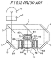
- a section having liquid crystal panels 6R, 6G and 6B and polarizers 5R, 5G, 5B, 7R, 7G and 7B accommodated within a hermetic container 13 is cooled by a cooling fan 11.
- This liquid crystal display apparatus operates as follows.
- Light emitted from a light source 1 becomes incident on a polarized beam splitter 2 and is split into P-polarized light and S-polarized light thereby.
- the P(S)-polarized light component outgoing from the polarized beam splitter 2 is further split into beams having respective wavelengths corresponding to three primary colors (red, green and blue) for which respective liquid crystal panels 6R, 6G and 6B are adapted by dichroic mirrors 3 and reflection mirrors 4.
- These beams are optically modulated by respective liquid crystal panels 6R, 6G and 6B, then become incident on a prism 8, pass through a projecting lens 9, and are enlargedly projected onto a screen.
- Liquid crystal display sections for red, green and blue comprising the polarizers 5R, 5G and 5B on the incident side, the liquid crystal panels 6R, 6G and 6B, and polarizers 7R, 7G and 7B on the outgoing side are disposed within the hermetic container 13 and adapted to be air-cooled by the cooling fan 11.
- the display sections are respectively enclosed by ducts 18R, 18G and 18B each having a sectional area substantially equal to the size of a blowing port through which air flows toward the liquid crystal panels 6R, 6G and 6B and the polarizers 5R, 5G, 5B, 7R, 7G and 7B.
- Such conventional liquid crystal display apparatus involves the following problems.
- the invention is made to solve the problems, and an object is to provide a liquid crystal display apparatus in which liquid crystal panels and polarizers can be effectively cooled by a simple arrangement.
- the invention provides a liquid crystal display apparatus comprising a light source, a hermetic container, and liquid crystal display sections for red, green and blue, respectively, disposed within the hermetic container, the liquid crystal display sections each having a liquid crystal panel and a polarizer, wherein light emitted from the light source is enlarged and projected, the liquid crystal display apparatus further comprising a first blower for sending cooling air to the liquid crystal display section for blue, and a second blower for sending cooling air to the liquid crystal display sections for red and green, the first and second blowers being disposed within the hermetic container.
- the first and second blowers comprise a multiblade fan and an axial flow fan, respectively.
- the first and second blowers each comprise an axial flow fan, and the second fan is adapted to send cooling air to one of the liquid crystal display section for red and the liquid crystal display section for green and then to the other liquid crystal display section.
- one of the first and second fans comprises an axial flow fan which is spaced apart from the hermetic container, and a reinforcing member is provided in a portion of the hermetic container which portion is opposite to the axial flow fan.
- a side plate is provided between the liquid crystal panel and the polarizer of each of the liquid crystal display sections for respective colors to be placed outside an image displaying portion of the liquid crystal panel and be perpendicular to the polarizer.
- the invention also provides a liquid crystal display apparatus comprising a light source, a hermetic container, liquid crystal display sections for red, green and blue, respectively, disposed within the hermetic container, the liquid crystal display sections each having a liquid crystal panel and a polarizer, wherein light emitted from the light source is enlarged and projected, the liquid crystal display apparatus further comprising blowing means for sending cooling air to the liquid crystal display sections for red, green and blue at a ratio of approximately 1 : 1 : 4, respectively.
- the combinations of polarizers and liquid crystal panels corresponding to red, green and blue are disposed within the hermetic container to prevent dust from adhering to any liquid crystal display section, and the polarizers and the liquid crystal panels can be efficiently cooled.
- the inventor of the invention has measured the surface temperatures of a polarizer and a liquid crystal panel of each liquid crystal display section for each color in a liquid crystal display apparatus and calculated the respective thermal fluxes of the liquid crystal display sections for red, green and blue, to discover the fact that the thermal flux of the display section for blue is greater than those of the display sections for red and green.
- the thermal fluxes of display sections for red, green and blue were determined as follows:
- the thermal flux of the liquid crystal panel for blue was about twice as large as those of the liquid crystal panels for red and green.
- the heat transfer coefficient of a liquid crystal display section for each color (comprising a liquid crystal panel, a polarizer on the incident side, and a polarizer on the outgoing side) is represented as K
- the temperature of each display section as T p
- the temperature of cooling air as T c
- the flow velocity of air at the surface of the liquid crystal panel for blue i.e., the cooling air flow at the display section for blue
- the flow velocity of air at the surface of the liquid crystal panel for blue needs to be about four times as high as those at the surfaces of the liquid crystal panels for red and green so as to maintain the temperatures of the three display sections to a substantially equal value.
- the invention makes it possible to cool these liquid crystal display sections for respective colors appropriately by relying upon a simple arrangement in which the installation of fans is devised.
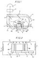
- Fig. 1 is a schematic view illustrating one embodiment according to the invention.
- Light emitted from a light source 1 becomes incident on a polarized beam splitter 2 and is split into P-polarized light and S-polarized light thereby.
- the P(S)-polarized light component outgoing from the polarized beam splitter 2 is further split into beams having respective wavelengths corresponding to three primary colors (red, green and blue) for which liquid crystal panels 6R, 6G and 6B are respectively adapted.
- These beams pass through polarizers 5R, 5G and 5B, respectively, on the incident side, are optically modulated by respective liquid crystal panels 6R, 6G and 6B, pass through respective polarizers 7R, 7G and 7B on the outgoing side, then become incident on a prism 8, and pass through a projecting lens 9 to provide an enlarged projection on a screen.
- All the components of the optical system except the light source 1 and the polarized beam splitter 2 are accommodated within the hermetic container 13 so as to prevent dust sucked from the outside by air flow from adhering to the liquid crystal panels 6R, 6G and 6B. Such dust, if adhering to the panels, would be projected as shadow in a displayed image thereby lowering the display quality.
- the polarizers on the incident side, liquid crystal panels and polarizers on the outgoing side for respective colors form liquid crystal display sections 50R, 50G, and 50B adapted for respective colors.
- the cooling system for the liquid crystal display sections 50R, 50G and 50B in the liquid crystal display apparatus is described below.
- this embodiment is a closed system in which the liquid crystal display sections 50R, 50G and 50B are accommodated within the hermetic container 13, heat generated by the liquid crystal display sections 50R, 50G and 50B is transferred to air within the hermetic container 13, then to the walls of the container 13, and finally dissipated to the outside from the container walls. For this reason, the temperature of cooling air is relatively high as compared with the case of using outside air directly as cooling air.
- the temperature difference between the highest temperature of the liquid crystal panels 6R, 6G and 6B and the temperature of cooling air in the closed system is 15°C, while such a temperature difference in an open system directly using outside air directly as cooling air is 20°C. Therefore, the flow velocity of air required in the closed system is (20/15) 2 times, i.e., about 1.8 times as high as that required in the open system when calculated based on equation (1). Namely, the cooling air flow required in the closed system is about 1.8 times as large as that required in the open system.
- the distribution of cooling air to each of the liquid crystal panels 6R, 6G and 6B in the closed system is considered.
- the pressure loss of cooling air during passage through a liquid crystal display section is in proportion to the flow velocity of cooling air
- a cooling fan to be provided in the closed system should be capable of generating a pressure about twice as high as that provided in the open system and sending an air flow twice as large as that in the open system, according to calculation based on equation (1).
- the cooling system should be designed so that cooling air passing through the liquid crystal panel 6B for blue may have a pressure and an air flow four times as large as that passing through other liquid crystal panels 6G and 6R.
- this embodiment is provided with one axial flow fan (blowing means: second fan) 11 under the liquid crystal display sections 50R and 50G for red and green and another axial flow fan (blowing means: first fan) 12 under the liquid crystal display section 50B for blue.
- Fig. 2 is a sectional view taken on line B-B in Fig. 1 for illustrating cooling air streams generated by the axial flow fans 11 and 12.
- cooling air 14 from the axial flow fan 11 first passes through the liquid crystal display sections 50R and 50G for red and green.
- the cooling air 14 absorbs heat from the liquid crystal panels 6R and 6G and the polarizers 5R, 7R, 5G and 7G and, hence, the temperature thereof rises.
- the cooling air 14 reaches the top wall of the hermetic container 13 and the temperature thereof lowers during passage through other components than the liquid crystal display sections.
- the cooling air 14 reaches the sucking side of the axial flow fan 11 and again circulates toward the liquid crystal display sections 50R and 50G. Distribution of cooling air from the axial flow fan 11 is achieved by guider 20 and the like.
- cooling air 14' from the axial flow fan 12 first passes through the liquid crystal display section 50B for blue. At this time, the cooling air 14' absorbs heat from the liquid crystal panels 6B and the polarizers 5B and 7B and, hence, the temperature thereof rises. Subsequently, the cooling air 14' reaches the top wall of the hermetic container 13 and the temperature thereof lowers during passage through other components than the liquid crystal display section. Then, the cooling air 14' reaches the sucking side of the axial flow fan 12 and again circulates toward the liquid crystal display section 50B. As described above, the axial flow fan 12 desirably has an ability four times as high as the axial flow fan 11 for the display sections for red and green.
- each of the liquid crystal display sections 50R and 50G for red and green requires a cooling air flow of 1.8 and, hence, a fan having an ability to send a cooling air flow of no more than 3.6 should be used as the cooling fan 11 for cooling liquid crystal display sections 50R and 50G for red and green.
- the display section 50B for blue requires a cooling air flow of 7.2, which is four times as large as 1.8, and hence a fan having an ability to send a cooling air flow of 7.2 should be used as the axial flow fan 12 for cooling the display section 50B for blue.
- a fan having an ability 0.6 times as high as the cooling fan used in the open system shown in Fig. 12 should be used as the cooling fan 11 for the display sections 50R and 50G for red and green and that a fan having an ability 1.2 times as high as the cooling fan used in the open system shown in Fig. 12 should be used as the cooling fan 12 for the display section 50B for blue.
- blowing means for use in the liquid crystal display apparatus of the invention is not limited thereto, but may be any means which can send cooling air to the liquid crystal display sections 50R, 50G and 50B for red, green and blue at a ratio of about 1 : 1 : 4, respectively.
- axial flow fans are used as the cooling fans for the liquid crystal display section for blue and for the liquid crystal display sections for red and green in embodiment 1
- the axial flow fan in general, has a problem that when the pressure generated by the axial flow fan increases, the air flow decreases extremely.
- This embodiment employs a multiblade fan as the cooling fan for the liquid crystal display section for blue to solve such a problem. This embodiment is described below with reference to the drawings.
- Fig. 3 is a schematic view showing the principal part of a liquid crystal display apparatus according to this embodiment.
- Fig. 4 is a sectional view taken on line B-B in Fig. 3 for illustrating cooling air streams in the embodiment.
- This embodiment is different from embodiment 1 in that a multiblade fan 12A is used instead of the axial flow fan as the cooling fan for the liquid crystal display section for blue. Since other parts are similar to the corresponding parts of embodiment 1, description thereof is omitted.
- the multiblade fan 12A is of a nature that even when a generated pressure increases, a decrease in air flow is small.
- the multiblade fan 12A sucks air from above and sends air laterally.
- the arrangement shown in Figs. 3 and 4 is provided with an air guide path 10.
- the air guide path 10 has a small radius of curvature so as to be compactly accommodated within the hermetic container 13. Further, the multiblade fan 12A is fixed as contacting the bottom plate 13A. In this case, the vibration of the motor of the multiblade fan 12A is transmitted directly to the hermetic container 13. To suppress noise caused by such vibration, it is possible to fix the multiblade fan 12A by inserting a vibration insulator (for example, rubber vibration insulator) 16 between the motor section of the multiblade fan 12A and the bottom plate 13A of the hermetic container 13.
- Fig. 9 is a diagram showing the noise-reducing effect resulted when the vibration insulator 16 was used. As shown, the presence of the vibration insulator 16 in this embodiment prevented generation of large noise at about 400 Hz.
- cooling air from the multiblade fan 12A is led to the liquid crystal display section 50B for blue and absorbs heat from the liquid crystal panel 6B and the polarizers 5B and 7B, with the result that the temperature of the cooling air rises. Subsequently, the cooling air reaches the top wall of the hermetic container 13 and the temperature thereof lowers during passage through other components than the liquid crystal display section. Then, the cooling air 14 reaches the sucking side of the multiblade fan 12A and again circulates toward the liquid crystal display section 50B. It should be noted that though the sucking side of the multiblade fan 12A is oriented upward in Fig. 4, it may be oriented downward in a case where the hermetic container 13 still has a sufficient space.
- the axial flow fan 11 is used as the cooling fan for sending cooling air to the liquid crystal display sections 50R and 50G for red and green.
- the liquid crystal display sections are arranged as shown in Figs. 1 and 3 and, hence, wind generated by the blades of the fan can be utilized only partially.
- the guider 20 as shown in Figs. 2 and 4 is used to distribute circulating air depending on the heat value of each display section.
- Table 1 shows the results of measurement of a temperature rise at each liquid crystal panel and at each polarizer in the arrangement described above by the use of a non-contact thermometer.
- Table 1 is shown an averaged value of temperature rises at the liquid crystal panel and polarizers of each display section when the axial flow fan 11 and the multiblade fan 12A were both driven at a constant voltage of 12V.
- a temperature rise resulted when the arrangement of the conventional art shown in Fig. 12 was driven at a constant voltage of 12 V is also shown in Table 1.
- Arrangement of embodiment 2 Arrangement shown in Fig. 12 Liquid crystal panel and polarizers for red 21.1°C 22.7°C Liquid crystal panel and polarizers for green 20.4°C 24.3°C Liquid crystal panel and polarizers for blue 22.3°C 28.2°C
- the arrangement of embodiment 2 minimized the difference in temperature rise among the display sections for respective colors and suppressed the temperature rise at each display section, while on the other hand the arrangement of Fig. 12 using a single axial flow fan could neither sufficiently reduce the difference in temperature rise among the display sections for respective colors nor suppress the temperature rise at each display section. Even when the driving voltage was raised in the arrangement of Fig. 12, the difference in temperature rise among the display sections for respective colors could not be sufficiently suppress though the temperature rise at each display section could be suppressed.
- the liquid crystal display apparatus of this embodiment thus described exhibits, in addition to the effect of embodiment 1, an effect of stably circulating cooling air.
- Such vibration can be reduced by taking measures such as making the bottom plate thicker. In this case, however, the bottom plate is entirely made thicker in spite of the fact that the vibration is generated from the space under the axial flow fan. This makes resin molding difficult and leads to an increase in cost.
- Fig. 7 illustrates a liquid crystal display apparatus in which the bottom plate 13A is reinforced at a portion under the axial flow fan 11 to solve such a problem. Specifically, five ribs (reinforcing members each having a width of 3 mm and a height of 3 mm) 15 are provided as angled relative to the bottom plate 13A.
- Fig. 8 is a diagram showing a noise-reducing effect of this arrangement. As apparently seen from Fig. 8, the provision of the ribs 15 reduced noise caused by vibration of the bottom plate 13A by virtue of the increased rigidity of the bottom plate 13A.
- rod-shaped ribs are provided in the arrangement of Fig. 7, there may be employed any reinforcing means such as using plate-shaped ribs or thickening the bottom plate 13A. It is to be noted that the number and position of these ribs should be determined depending on the configuration and specifications of the hermetic container 13 and the specifications of the axial flow fan 11 used.
- a liquid crystal display apparatus differs from those of embodiments 1 and 2 in that a multiblade fan is used as the cooling fan for the liquid crystal display sections for red and green, as well as for the liquid crystal display section for blue.
- the liquid crystal display apparatus of this embodiment is described below but description of like or similar parts corresponding to those of embodiments 1 and 2 is omitted.
- Fig. 5 is a schematic view showing the arrangement of the liquid crystal display apparatus according to this embodiment in which a multiblade fan 11A is used for the liquid crystal display sections 50R and 50G also.
- Fig. 6 is a sectional view taken on line B-B in Fig. 5 for illustrating cooling air streams in this embodiment.
- the multiblade fan 11A sucks air 14 from around the liquid crystal display section components 5R, 6R and 7R for red, and the flow of air is changed by an air guide path 21 and sent toward the liquid crystal display section 50G for green.
- the cooling air 14 absorbs heat from the liquid crystal display section 50G for green, dissipates heat during its passage inside the hermetic container 13 to lower its temperature, passes through the liquid crystal display section 50R for red while absorbing heat thereof to raise its temperature, and returns to the multiblade fan 11A.
- the multiblade fan 11A is arranged to suck air from around the liquid crystal display section 50R for red in Figs. 5 and 6, it may be arranged to suck air from around the liquid crystal display section 50G for green and sends air toward the liquid crystal display section 50R for red.
- the heat value of each liquid crystal display section can be represented by equation (1).
- T p'' Q/K (1/ ⁇ 2 + K/( ⁇ C p 2V)) - T c
- T p'' smaller than T p obtained by equation (3), it is required that (1/ ⁇ 2 + K/( ⁇ C p 2V) should be 1 or smaller. Where K/ ⁇ C p V is 0.77 or smaller, it is preferable to use the multiblade fan to lower the temperature.
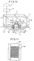
- Fig. 10 shows a liquid crystal display apparatus according to this embodiment in which the closed-system liquid crystal display apparatus of embodiment 2 is further provided with side plates 17R, 17G and 17B which are parallel to the optical axis and perpendicular to respective liquid crystal panels and polarizers.
- These side plates 17R, 17G and 17B are positioned perpendicular to respective liquid crystal panels 6R, 6G and 6B and polarizers 5R, 5G, 5B, 7R, 7G and 7B so that cooling air is sent to portions desired to be cooled of these display sections and polarizers.
- Fig. 11 is an illustration for explaining the position of each of the side plates 17R, 17G and 17B. As shown, each of the side plates 17R, 17G and 17B is positioned adjacent an imaging portion (shaded portion in Fig. 11). When the cooling ability of this arrangement was compared with that of embodiment 2, a temperature rise at each display section could be reduced by about 2°C.
- each of these side plates 17R, 17G and 17B is not limited to a plate, but may be any material which can form a side surface.
Landscapes
- Physics & Mathematics (AREA)
- Engineering & Computer Science (AREA)
- Signal Processing (AREA)
- Multimedia (AREA)
- Nonlinear Science (AREA)
- Crystallography & Structural Chemistry (AREA)
- Optics & Photonics (AREA)
- General Physics & Mathematics (AREA)
- Chemical & Material Sciences (AREA)
- Mathematical Physics (AREA)
- Liquid Crystal (AREA)
- Projection Apparatus (AREA)
- Devices For Indicating Variable Information By Combining Individual Elements (AREA)
Abstract
Description
- Red
- : 0.235 W/cm2
- Green
- : 0.251 W/cm2
- Blue
- : 0.405 W/cm2
| Arrangement of | Arrangement shown in Fig. 12 | |
| Liquid crystal panel and polarizers for red | 21.1°C | 22.7°C |
| Liquid crystal panel and polarizers for green | 20.4°C | 24.3°C |
| Liquid crystal panel and polarizers for blue | 22.3°C | 28.2°C |
Claims (9)
- A liquid crystal display apparatus comprising:a light source (1);a hermetic container (13); andliquid crystal display sections (50R, 50G, 50B) for red, green and blue, respectively, disposed within the hermetic container (13), the liquid crystal display sections each having a liquid crystal panel (6R, 6G, 6B) and a polarizer (5R, 5G, 5B, 7R, 7G, 7B),
wherein light emitted from the light source (1) is enlarged and projected,the liquid crystal display apparatus further comprising:a first blower (12) for sending cooling air to the liquid crystal display section (50B) for blue; anda second blower (11) for sending cooling air to the liquid crystal display sections (50R, 50G) for red and green,the first and second blowers (12, 11) being disposed within the hermetic container (13). - The liquid crystal display apparatus of claim 1, wherein the first and second blowers (12, 11) comprise a multiblade fan and an axial flow fan, respectively.
- The liquid crystal display apparatus of claim 1, wherein the first and second blowers (12, 11) each comprise an axial flow fan, and the second fan (11) is adapted to send cooling air to one of the liquid crystal display section for red and the liquid crystal display section for green and then to the other liquid crystal display section.
- The liquid crystal display apparatus of claim 1, wherein one of the first and second fans (12, 11) comprises an axial flow fan which is spaced apart from the hermetic container (13), and a reinforcing member (15) is provided in a portion of the hermetic container (13) which portion is opposite to the axial flow fan.
- The liquid crystal display apparatus of claim 1, wherein a side plate (17R, 17G, 17B) is provided between the liquid crystal panel (6R, 6G, 6B) and polarizer (5R, 5G, 5B, 7R, 7G, 7B) of each of the liquid crystal display sections for red, green and blue to be placed outside an image displaying portion of the liquid crystal panel and be perpendicular to the polarizer.
- The liquid crystal display apparatus of claim 2, wherein a side plate (17R, 17G, 17B) is provided between the liquid crystal panel (6R, 6G, 6B) and polarizer (5R, 5G, 5B, 7R, 7G, 7B) of each of the liquid crystal display sections for red, green and blue to be placed outside an image displaying portion of the liquid crystal panel and be perpendicular to the polarizer.
- The liquid crystal display apparatus of claim 3, wherein a side plate (17R, 17G, 17B) is provided between the liquid crystal panel (6R, 6G, 6B) and polarizer (5R, 5G, 5B, 7R, 7G, 7B) of each of the liquid crystal display sections for red, green and blue to be placed outside an image displaying portion of the liquid crystal panel and be perpendicular to the polarizer.
- The liquid crystal display apparatus of claim 4, wherein a side plate (17R, 17G, 17B) is provided between the liquid crystal panel (6R, 6G, 6B) and polarizer (5R, 5G, 5B, 7R, 7G, 7B) of each of the liquid crystal display sections for red, green and blue to be placed outside an image displaying portion of the liquid crystal panel and be perpendicular to the polarizer.
- A liquid crystal display apparatus comprising:a light source (1);a hermetic container (13); andliquid crystal display sections (50R, 50G, 50B) for red, green and blue, respectively, disposed within the hermetic container (13), the liquid crystal display sections each having a liquid crystal panel (6R, 6G, 6B) and a polarizer (5R, 5G, 5B, 7R, 7G, 7B),
wherein light emitted from the light source (1) is enlarged and projected,the liquid crystal display apparatus further comprising:blowing means for sending cooling air to the liquid crystal display sections (50R, 50G, 50B) for red, green and blue at a ratio of approximately 1 : 1 : 4, respectively.
Applications Claiming Priority (2)
| Application Number | Priority Date | Filing Date | Title |
|---|---|---|---|
| JP20573199 | 1999-07-21 | ||
| JP20573199A JP3571965B2 (en) | 1999-07-21 | 1999-07-21 | Liquid crystal display |
Publications (3)
| Publication Number | Publication Date |
|---|---|
| EP1070979A2 true EP1070979A2 (en) | 2001-01-24 |
| EP1070979A3 EP1070979A3 (en) | 2001-10-10 |
| EP1070979B1 EP1070979B1 (en) | 2003-03-19 |
Family
ID=16511747
Family Applications (1)
| Application Number | Title | Priority Date | Filing Date |
|---|---|---|---|
| EP00115659A Expired - Lifetime EP1070979B1 (en) | 1999-07-21 | 2000-07-20 | Liquid crystal projector |
Country Status (4)
| Country | Link |
|---|---|
| US (1) | US6473150B1 (en) |
| EP (1) | EP1070979B1 (en) |
| JP (1) | JP3571965B2 (en) |
| DE (1) | DE60001692T2 (en) |
Families Citing this family (43)
| Publication number | Priority date | Publication date | Assignee | Title |
|---|---|---|---|---|
| JP5388394B2 (en) * | 2001-05-31 | 2014-01-15 | キヤノン株式会社 | Projection type image display device |
| JP2003241316A (en) * | 2002-02-21 | 2003-08-27 | Sony Corp | Projection display device |
| US7073911B2 (en) * | 2003-03-14 | 2006-07-11 | Seiko Epson Corporation | Projector with improved heat radiation |
| JP4093268B2 (en) * | 2005-12-26 | 2008-06-04 | ソニー株式会社 | Optical unit device for projection display device |
| US8854595B2 (en) | 2008-03-03 | 2014-10-07 | Manufacturing Resources International, Inc. | Constricted convection cooling system for an electronic display |
| US12185512B2 (en) | 2007-11-16 | 2024-12-31 | Manufacturing Resources International, Inc. | Electronic display assembly with thermal management |
| US8654302B2 (en) | 2008-03-03 | 2014-02-18 | Manufacturing Resources International, Inc. | Heat exchanger for an electronic display |
| US9173325B2 (en) | 2008-03-26 | 2015-10-27 | Manufacturing Resources International, Inc. | Heat exchanger for back to back electronic displays |
| US8497972B2 (en) | 2009-11-13 | 2013-07-30 | Manufacturing Resources International, Inc. | Thermal plate with optional cooling loop in electronic display |
| US8773633B2 (en) | 2008-03-03 | 2014-07-08 | Manufacturing Resources International, Inc. | Expanded heat sink for electronic displays |
| US8693185B2 (en) | 2008-03-26 | 2014-04-08 | Manufacturing Resources International, Inc. | System and method for maintaining a consistent temperature gradient across an electronic display |
| US8749749B2 (en) | 2008-12-18 | 2014-06-10 | Manufacturing Resources International, Inc. | System for cooling an electronic image assembly with manifolds and ambient gas |
| US10827656B2 (en) | 2008-12-18 | 2020-11-03 | Manufacturing Resources International, Inc. | System for cooling an electronic image assembly with circulating gas and ambient gas |
| JP2011075763A (en) * | 2009-09-30 | 2011-04-14 | Sanyo Electric Co Ltd | Projection type video display device |
| US8804091B2 (en) | 2010-08-20 | 2014-08-12 | Manufacturing Resources International, Inc. | System and method for thermally controlling an electronic display with reduced noise emissions |
| EP2909829B1 (en) | 2012-10-16 | 2020-02-12 | Manufacturing Resources International, INC. | Back pan cooling assembly for electronic display |
| WO2014150036A1 (en) | 2013-03-15 | 2014-09-25 | Manufacturing Resources International, Inc. | Cooling system for an electronic display |
| WO2014149773A1 (en) | 2013-03-15 | 2014-09-25 | Manufacturing Resources International, Inc. | Heat exchange assembly for an electronic display |
| KR101894027B1 (en) | 2013-07-08 | 2018-08-31 | 매뉴팩처링 리소시스 인터내셔널 인코포레이티드 | Figure eight closed loop cooling system for electronic display |
| WO2015138609A2 (en) | 2014-03-11 | 2015-09-17 | Manufacturing Resources International, Inc. | Hybrid rear cover and mounting bracket for eletronic display |
| KR101885884B1 (en) | 2014-04-30 | 2018-08-07 | 매뉴팩처링 리소시스 인터내셔널 인코포레이티드 | Back to back electronic display assembly |
| US9613548B2 (en) | 2015-01-06 | 2017-04-04 | Manufacturing Resources International, Inc. | Advanced cooling system for electronic display |
| US9723765B2 (en) | 2015-02-17 | 2017-08-01 | Manufacturing Resources International, Inc. | Perimeter ventilation system for electronic display |
| ES2909480T3 (en) | 2016-03-04 | 2022-05-06 | Mri Inc | Cooling system for double-sided display assembly |
| US10485113B2 (en) | 2017-04-27 | 2019-11-19 | Manufacturing Resources International, Inc. | Field serviceable and replaceable display |
| JP6824440B2 (en) | 2017-04-27 | 2021-02-03 | マニュファクチャリング・リソーシズ・インターナショナル・インコーポレーテッド | Systems and methods to prevent bending deformation of the display |
| US10559965B2 (en) | 2017-09-21 | 2020-02-11 | Manufacturing Resources International, Inc. | Display assembly having multiple charging ports |
| US10602626B2 (en) | 2018-07-30 | 2020-03-24 | Manufacturing Resources International, Inc. | Housing assembly for an integrated display unit |
| US11096317B2 (en) | 2019-02-26 | 2021-08-17 | Manufacturing Resources International, Inc. | Display assembly with loopback cooling |
| US10795413B1 (en) | 2019-04-03 | 2020-10-06 | Manufacturing Resources International, Inc. | Electronic display assembly with a channel for ambient air in an access panel |
| US11477923B2 (en) | 2020-10-02 | 2022-10-18 | Manufacturing Resources International, Inc. | Field customizable airflow system for a communications box |
| US11778757B2 (en) | 2020-10-23 | 2023-10-03 | Manufacturing Resources International, Inc. | Display assemblies incorporating electric vehicle charging equipment |
| US11470749B2 (en) | 2020-10-23 | 2022-10-11 | Manufacturing Resources International, Inc. | Forced air cooling for display assemblies using centrifugal fans |
| US12408312B2 (en) | 2021-07-28 | 2025-09-02 | Manufacturing Resources International, Inc. | Display assemblies with vents |
| US11966263B2 (en) | 2021-07-28 | 2024-04-23 | Manufacturing Resources International, Inc. | Display assemblies for providing compressive forces at electronic display layers |
| US11919393B2 (en) | 2021-08-23 | 2024-03-05 | Manufacturing Resources International, Inc. | Display assemblies inducing relatively turbulent flow and integrating electric vehicle charging equipment |
| US11744054B2 (en) | 2021-08-23 | 2023-08-29 | Manufacturing Resources International, Inc. | Fan unit for providing improved airflow within display assemblies |
| US11762231B2 (en) | 2021-08-23 | 2023-09-19 | Manufacturing Resources International, Inc. | Display assemblies inducing turbulent flow |
| US11968813B2 (en) | 2021-11-23 | 2024-04-23 | Manufacturing Resources International, Inc. | Display assembly with divided interior space |
| US12072561B2 (en) | 2022-07-22 | 2024-08-27 | Manufacturing Resources International, Inc. | Self-contained electronic display assembly, mounting structure and methods for the same |
| US12010813B2 (en) | 2022-07-22 | 2024-06-11 | Manufacturing Resources International, Inc. | Self-contained electronic display assembly, mounting structure and methods for the same |
| US12035486B1 (en) | 2022-07-25 | 2024-07-09 | Manufacturing Resources International, Inc. | Electronic display assembly with fabric panel communications box |
| US12598727B2 (en) | 2024-01-09 | 2026-04-07 | Manufacturing Resources International, Inc. | Double sided display assembly with bi-directional flow through a common, partitioned heat exchanger |
Family Cites Families (7)
| Publication number | Priority date | Publication date | Assignee | Title |
|---|---|---|---|---|
| JP3273372B2 (en) * | 1991-02-22 | 2002-04-08 | セイコーエプソン株式会社 | Projection type liquid crystal projector |
| JPH06194621A (en) * | 1992-12-25 | 1994-07-15 | Sony Corp | Liquid crystal projector |
| US6007205A (en) * | 1995-03-30 | 1999-12-28 | Seiko Epson Corporation | Optical lens unit having internalized fan unit and projection apparatus housing the same |
| JPH09113998A (en) | 1995-10-18 | 1997-05-02 | Sony Corp | Liquid crystal panel unit and liquid crystal projector |
| US5892561A (en) * | 1995-10-18 | 1999-04-06 | Fujitsu Limited | LC panel with reduced defects having adhesive smoothing layer on an exterior surface of the substrate(s) |
| JP3767047B2 (en) * | 1996-04-26 | 2006-04-19 | セイコーエプソン株式会社 | Projection display |
| JP3319996B2 (en) * | 1997-10-20 | 2002-09-03 | 株式会社日立製作所 | Video display mechanism and video display device |
-
1999
- 1999-07-21 JP JP20573199A patent/JP3571965B2/en not_active Expired - Fee Related
-
2000
- 2000-07-20 EP EP00115659A patent/EP1070979B1/en not_active Expired - Lifetime
- 2000-07-20 DE DE60001692T patent/DE60001692T2/en not_active Expired - Fee Related
- 2000-07-21 US US09/624,011 patent/US6473150B1/en not_active Expired - Fee Related
Also Published As
| Publication number | Publication date |
|---|---|
| DE60001692T2 (en) | 2003-12-18 |
| DE60001692D1 (en) | 2003-04-24 |
| JP3571965B2 (en) | 2004-09-29 |
| EP1070979A3 (en) | 2001-10-10 |
| US6473150B1 (en) | 2002-10-29 |
| JP2001033750A (en) | 2001-02-09 |
| EP1070979B1 (en) | 2003-03-19 |
Similar Documents
| Publication | Publication Date | Title |
|---|---|---|
| EP1070979B1 (en) | Liquid crystal projector | |
| US7152978B2 (en) | Liquid crystal projector, and projection lens unit, optical unit and cooling system for the same | |
| US6443575B1 (en) | Projector with inlet fan, outlet fan and ventilation duct structure for cooling an optical system | |
| US11330234B2 (en) | Electronic device and projectors | |
| US7364327B2 (en) | Projection type display unit | |
| US7083286B2 (en) | Projector having improved structure for cooling optical system | |
| EP0769714A1 (en) | Liquid crystal panel and liquid crystal projector | |
| JPWO2002019027A1 (en) | Projection type video equipment | |
| JP3639271B2 (en) | Projection display device and blower | |
| KR20010078771A (en) | Projection apparatus | |
| JP2002006282A (en) | Liquid crystal display | |
| US8690346B2 (en) | Projection display apparatus including wind outlets for cooling optical part | |
| JP2001042435A (en) | Projector device | |
| US20030179591A1 (en) | Cooling Apparatus for Optical Engine Assembly | |
| JP2944354B2 (en) | LCD projector | |
| JPH0829874A (en) | LCD projector | |
| JP3807219B2 (en) | projector | |
| JP2003107582A (en) | Cooling structure of projection type liquid crystal display | |
| JP2004279778A (en) | projector | |
| KR20030025343A (en) | Projection display device | |
| US20250172861A1 (en) | Heat dissipation module and projection device | |
| JPH06189240A (en) | Liquid crystal projector device | |
| US20250093758A1 (en) | Liquid cooling module and projection device | |
| JPH07181421A (en) | Video display | |
| JPH10325982A (en) | LCD projector |
Legal Events
| Date | Code | Title | Description |
|---|---|---|---|
| PUAI | Public reference made under article 153(3) epc to a published international application that has entered the european phase |
Free format text: ORIGINAL CODE: 0009012 |
|
| AK | Designated contracting states |
Kind code of ref document: A2 Designated state(s): DE FR GB Kind code of ref document: A2 Designated state(s): AT BE CH CY DE DK ES FI FR GB GR IE IT LI LU MC NL PT SE |
|
| AX | Request for extension of the european patent |
Free format text: AL;LT;LV;MK;RO;SI |
|
| PUAL | Search report despatched |
Free format text: ORIGINAL CODE: 0009013 |
|
| RIC1 | Information provided on ipc code assigned before grant |
Free format text: 7G 02F 1/13 A, 7H 04N 9/31 B, 7G 02F 1/133 B |
|
| AK | Designated contracting states |
Kind code of ref document: A3 Designated state(s): AT BE CH CY DE DK ES FI FR GB GR IE IT LI LU MC NL PT SE |
|
| AX | Request for extension of the european patent |
Free format text: AL;LT;LV;MK;RO;SI |
|
| 17P | Request for examination filed |
Effective date: 20011227 |
|
| 17Q | First examination report despatched |
Effective date: 20020319 |
|
| AKX | Designation fees paid |
Free format text: DE FR GB |
|
| GRAH | Despatch of communication of intention to grant a patent |
Free format text: ORIGINAL CODE: EPIDOS IGRA |
|
| GRAH | Despatch of communication of intention to grant a patent |
Free format text: ORIGINAL CODE: EPIDOS IGRA |
|
| GRAA | (expected) grant |
Free format text: ORIGINAL CODE: 0009210 |
|
| AK | Designated contracting states |
Designated state(s): DE FR GB |
|
| REG | Reference to a national code |
Ref country code: GB Ref legal event code: FG4D |
|
| REF | Corresponds to: |
Ref document number: 60001692 Country of ref document: DE Date of ref document: 20030424 Kind code of ref document: P |
|
| ET | Fr: translation filed | ||
| PLBE | No opposition filed within time limit |
Free format text: ORIGINAL CODE: 0009261 |
|
| STAA | Information on the status of an ep patent application or granted ep patent |
Free format text: STATUS: NO OPPOSITION FILED WITHIN TIME LIMIT |
|
| 26N | No opposition filed |
Effective date: 20031222 |
|
| PGFP | Annual fee paid to national office [announced via postgrant information from national office to epo] |
Ref country code: DE Payment date: 20060713 Year of fee payment: 7 |
|
| PGFP | Annual fee paid to national office [announced via postgrant information from national office to epo] |
Ref country code: FR Payment date: 20060719 Year of fee payment: 7 Ref country code: GB Payment date: 20060719 Year of fee payment: 7 |
|
| GBPC | Gb: european patent ceased through non-payment of renewal fee |
Effective date: 20070720 |
|
| PG25 | Lapsed in a contracting state [announced via postgrant information from national office to epo] |
Ref country code: DE Free format text: LAPSE BECAUSE OF NON-PAYMENT OF DUE FEES Effective date: 20080201 |
|
| PG25 | Lapsed in a contracting state [announced via postgrant information from national office to epo] |
Ref country code: GB Free format text: LAPSE BECAUSE OF NON-PAYMENT OF DUE FEES Effective date: 20070720 |
|
| REG | Reference to a national code |
Ref country code: FR Ref legal event code: ST Effective date: 20080331 |
|
| PG25 | Lapsed in a contracting state [announced via postgrant information from national office to epo] |
Ref country code: FR Free format text: LAPSE BECAUSE OF NON-PAYMENT OF DUE FEES Effective date: 20070731 |