EP1070828A2 - Heave compensator - Google Patents
Heave compensator Download PDFInfo
- Publication number
- EP1070828A2 EP1070828A2 EP00202354A EP00202354A EP1070828A2 EP 1070828 A2 EP1070828 A2 EP 1070828A2 EP 00202354 A EP00202354 A EP 00202354A EP 00202354 A EP00202354 A EP 00202354A EP 1070828 A2 EP1070828 A2 EP 1070828A2
- Authority
- EP
- European Patent Office
- Prior art keywords
- winch
- cable
- wireline
- logging
- vertical motion
- Prior art date
- Legal status (The legal status is an assumption and is not a legal conclusion. Google has not performed a legal analysis and makes no representation as to the accuracy of the status listed.)
- Granted
Links
Images




Classifications
-
- B—PERFORMING OPERATIONS; TRANSPORTING
- B66—HOISTING; LIFTING; HAULING
- B66D—CAPSTANS; WINCHES; TACKLES, e.g. PULLEY BLOCKS; HOISTS
- B66D1/00—Rope, cable, or chain winding mechanisms; Capstans
- B66D1/28—Other constructional details
- B66D1/40—Control devices
- B66D1/48—Control devices automatic
- B66D1/50—Control devices automatic for maintaining predetermined rope, cable, or chain tension, e.g. in ropes or cables for towing craft, in chains for anchors; Warping or mooring winch-cable tension control
- B66D1/505—Control devices automatic for maintaining predetermined rope, cable, or chain tension, e.g. in ropes or cables for towing craft, in chains for anchors; Warping or mooring winch-cable tension control electrical
-
- E—FIXED CONSTRUCTIONS
- E21—EARTH OR ROCK DRILLING; MINING
- E21B—EARTH OR ROCK DRILLING; OBTAINING OIL, GAS, WATER, SOLUBLE OR MELTABLE MATERIALS OR A SLURRY OF MINERALS FROM WELLS
- E21B19/00—Handling rods, casings, tubes or the like outside the borehole, e.g. in the derrick; Apparatus for feeding the rods or cables
- E21B19/02—Rod or cable suspensions
-
- E—FIXED CONSTRUCTIONS
- E21—EARTH OR ROCK DRILLING; MINING
- E21B—EARTH OR ROCK DRILLING; OBTAINING OIL, GAS, WATER, SOLUBLE OR MELTABLE MATERIALS OR A SLURRY OF MINERALS FROM WELLS
- E21B19/00—Handling rods, casings, tubes or the like outside the borehole, e.g. in the derrick; Apparatus for feeding the rods or cables
- E21B19/08—Apparatus for feeding the rods or cables; Apparatus for increasing or decreasing the pressure on the drilling tool; Apparatus for counterbalancing the weight of the rods
- E21B19/09—Apparatus for feeding the rods or cables; Apparatus for increasing or decreasing the pressure on the drilling tool; Apparatus for counterbalancing the weight of the rods specially adapted for drilling underwater formations from a floating support using heave compensators supporting the drill string
-
- Y—GENERAL TAGGING OF NEW TECHNOLOGICAL DEVELOPMENTS; GENERAL TAGGING OF CROSS-SECTIONAL TECHNOLOGIES SPANNING OVER SEVERAL SECTIONS OF THE IPC; TECHNICAL SUBJECTS COVERED BY FORMER USPC CROSS-REFERENCE ART COLLECTIONS [XRACs] AND DIGESTS
- Y10—TECHNICAL SUBJECTS COVERED BY FORMER USPC
- Y10S—TECHNICAL SUBJECTS COVERED BY FORMER USPC CROSS-REFERENCE ART COLLECTIONS [XRACs] AND DIGESTS
- Y10S254/00—Implements or apparatus for applying pushing or pulling force
- Y10S254/90—Cable pulling drum having wave motion responsive actuator for operating drive or rotation retarding means
Definitions
- a device mounted close to the cable drum at the surface determines the depth at which these measurements are recorded. This device measures cable movement into and out of the well and is known as the depth system.
- the wireline well log contains the record of the series of measurements of the formations and fluids found in the wellbore with respect to the location within the borehole at which measurements are made.
- the raw measurements are often presented in the form of an x-y graph with the location where the measurement is made recorded on the y-axis and the measurement itself recorded on the x-axis.
- the location where the measurement is made is called the depth. It is a measure of the distance between a reference position, usually located somewhere on the surface above the well, and the location within the borehole following the path of the borehole.
- a fixed wireline setup such as a land drilling rig or fixed offshore platform
- the measurement of depth and cable speed is relatively straightforward. This is because the variables in the system can be measured and accounted for.
- On a land rig or fixed drilling rig there is a fixed distance between a reference point at the surface of the well itself and the winch. Because the distance is fixed, it may be automatically adjusted out of the depth calculation.
- the winch is installed on a floating vessel, which may typically be a semisubmersible rig, drill ship or barge, the movement of the rig itself due to tidal or wave motion effects is not taken into account by conventional wireline logging systems.
- an electro-mechanical compensation device can be inserted between the winch and the upper sheave wheel to be used for well logging only. Since well logging is done somewhat infrequently, this device is often idle. In both of these types of systems, no corrections are made for any errors induced by incomplete heave compensation.
- the present invention solves the problem of wave motion on wireline logging data firstly by physically compensating for vertical motion (heave) at the wireline winch and secondly, by calculating and recording any errors in that physical compensation so that the true depth at which a wireline log data measurement is made is recorded, along with the wireline well log measurement.
- Both the physical compensation system and the recording of errors in that physical compensation system utilize information on the physical movement of the rig itself, obtained from a motion reference unit (MRU).
- MRU motion reference unit
- An electrically controlled wireline winch provides for the physical heave compensation.
- the wireline winch is fixed to the rig structure itself with no external compensation system connected.
- the movement of the wireline cable due to heave is measured by the MRU and is compensated for by the winch with a corresponding change in motion and/or direction of the wireline cable. This ensures that the wireline logging data is acquired at a constant, known speed. Any error in this compensation is detected by the depth system within a data acquisition computer located at the surface, recorded and may be used to adjust the true depth at which the wireline log measurements are being recorded.
- the present invention comprises a system and method for compensating for the vertical motion of a floating vessel having a winch control means for receiving vessel vertical motion data and logging tool speed set points and a wireline winch means for raising and lowering a wireline cable within a wellbore, connected to the winch control means and comprising a winch motor for attaching to and rotatably moving a cable drum, the wireline cable having at least one logging measurement tool attached to an end of the wireline cable extending from the cable drum.
- the winch control means combines the vertical motion data and logging tool speed set points to produce a winch motor control signal for controlling the rotatable movement of the cable drum so as to cause the wireline cable to achieve movement within the wellbore at a controlled speed, which may be substantially constant, independent of vessel vertical motion.
- the system can also compensate for the vertical motion of a floating vessel using a winch control means for receiving vessel vertical motion data and logging tool tension set points and a wireline winch means for raising and lowering a wireline cable within a wellbore, connected to the winch control means and comprising a winch motor for attaching to and rotatably moving a cable drum, the wireline cable having at least one logging measurement tool attached to an end of the wireline cable extending from the cable drum.
- the winch skid 11 is able to receive a cable drum 22, which can be a large or small drum using either a heptacable or monocable setup.
- Logging tools 20 are attached to one end of the wireline cable 15.
- a wireline computer 16 interfaces with the winch controller 14.
- a cable movement measuring device 12, which measures cable speed and tension as the cable exits the cable drum 22, is gimbal mounted and located just outside the winch 10 and comprises two wheels located side by side with the wireline cable 15 running between the wheels.
- the cable movement measuring device may comprise one device or two devices. If there are two devices, one usually measures cable speed and another cable tension. As the wireline cable 15 moves, the cable movement measuring device measures the amount and direction of wheel rotation electronically.
- An upper sheave wheel 17 and lower sheave wheel 18 are used to align the wireline cable 15 with the well and the winch.
- a motion reference unit (MRU) 19 located near the wireline cable 15 provides measured vertical position, speed and acceleration of the floating rig 13 at the derrick floor and provides that information to the winch controller 14, which uses the information along with measurement data from the cable movement measuring device 12 to control the winch 10 and physically compensate for vertical motion on the wireline cable 15 by changing the speed and/or direction of the wireline cable 15 motion.
- the winch controller 14 also provides the vertical motion information to the wireline computer 16.
- the wireline computer 16 uses the vertical motion information and the measurement data from the cable movement measuring device 12 to detect any errors in the physical compensation and to record the true depth at which the wireline log measurements are taken.
- Fig. 3 is a block diagram of the physical heave compensation system and the physical correction made by the winch.
- the motion reference unit (MRU) 30 detects vertical motion of the drilling platform, which is used by the winch controller 31 and the wireline computer depth measurement processing 32. Based on the vertical motion, the winch controller 31 calculates the necessary changes in the winch motor 34 speed and direction to keep the wireline cable 37 and the wireline logging tool 36 at a constant or controlled speed while being lowered or raised in the wellbore.
- the winch controller 31 sends a command to change speed and direction to the winch motor drive 33, which in turn controls the winch motor 34.
- the cable movement measuring device (CMMD) 35 measures cable motion and tension of the wireline cable 37 as it exits the winch drum.
- CMMD cable movement measuring device
- This measurement takes into account the amount of correction physically applied to the wireline cable 37 and the measurement is sent to the wireline computer 32.
- the depth measurement system within the wireline computer detects any error in this compensation by comparing the actual vertical motion as measured by the MRU 30 with the physical correction made by the winch. Any error in the physical compensation may be used to adjust the true depth at which the measurements are being recorded.
- the winch controller 40 comprises a programmable logic controller (PLC) 41 and a winch motor drive 42, which may be a variable speed drive.
- PLC programmable logic controller
- the winch controller 40 computes the parameters for accurately controlling the motion of the wireline winch 46.
- the motion of the winch is achieved through the winch motor drive 42 and motor 43, which are connected using an electrical cable.
- the winch motor drive 42 can accurately control the winch motor 43 using the motor frequency and voltage.
- An encoder mounted on the motor shaft is connected to the winch motor drive so that increased precision may be achieved.
- the winch remote I/O 44 communicates with the PLC 41.
- the winch remote I/O 44 collects information and sends commands to ancillary systems on the winch such as the brakes, steering, oscillating, light, operator backup control panel (BCT) 48 and general alarms.
- the motion reference unit 47 provides the vertical information about the floating rig or vessel to the winch controller 40 which is forwarded to the depth measurement system 54 processing in the wireline computer 53.
- the winch controller 40 uses the vertical information (which comprises position, speed and acceleration) to calculate the necessary physical compensation in motor 43 speed and direction to keep the wireline cable 55 and the wireline logging tool 50 at a constant speed.
- the depth measuring system 54 within the wireline computer 53 accepts the measured cable speed and tension from the cable movement measuring device 49.
- the depth measuring system 54 uses the vertical position from the MRU 47, through the gateway controller computer 52, and the measured cable speed and tension, the depth measuring system 54 computes any error in the physical compensation to calculate the logging depth at which the wireline logging measurements are made, which is then recorded by the wireline logging software. This information is sent back to the winch controller 40 through the gateway controller 52 which provides the interface between the depth measurement system 54 and the PLC 41. Commands from the operator are input from a winch control panel and display human machine interface (HMI) 51, which contains operator controls and displays. The HMI 51 may also be used to control other functions for different rig processes such as drilling or pumping.
- HMI human machine interface
- the winch controller 40 processes wireline computer 53 and motion reference unit 47 information and operator commands from the HMI 51 to determine the required motor 43 speed and torque and sends this information to the winch motor drive 42 for execution.
- the winch motor drive 42 which may be a variable speed, alternating current motor drive, receives RPM/torque commands and generates the required electrical signals for controlling the winch motor 43.
- the winch motor drive 42 has its own built-in sensors for RPM (with a tachometer mounted on the motor) and torque. It exchanges the start/stop and brake on/off status with the PLC 41. The winch controller 40 then energizes the brake accordingly through the winch remote I/O 44.
- the winch devices 46 are electric and electro-pneumatic components that control braking, oscillating, spooling and other winch functions. These components are activated through the winch remote I/Os 44.
- An operator backup panel human machine interface (HMI) 48 is used for backup control and allows the operator to perform a reduced set of operator commands.
- the operator backup panel HMI 48 can be used in place of the winch control panel, when for example, the operator interface HMI 51 is being used to control other functions for different rig processes.
- the operator panel HMI 48 is linked to the winch controller via the winch remote I/Os 44.
- the depth measuring system 54 interfaces with an alarm and control display 56 for displaying alarm and control status information to an operator.
- the cable drum 45 can be a large or small drum with either heptacable or monocable.
- the cable drum 45 can have a flange diameter between about thirty inches and sixty inches and a cable length maximum capacity of about 40,000 ft. depending on the cable flange diameter and cable diameter.
- the cable drum 45 may be equipped with a one and one half inch pitch sprocket (between about 72 and 80 teeth), pillow blocks and a brake band surface on both sides of the cable drum 45.
- the winch In normal mode (not wave compensated), with a 140kVA (110kW) variable speed drive and depending upon the type and size of the cable drum, the winch allows for the delivery of a maximum cable speed of about 54,000 ft/hr and a minimum cable speed of about 42 ft/hr and a maximum pull on line of 26,100 lbs.
- the winch controller programmable logic controller (PLC) 60 communicates with the winch controller/winch motor drive 61, the gateway controller computer 62, winch remote I/O (WRIO) 63 and motion reference unit one (MRU 1) 75 and motion reference unit two (MRU 2) 76 via a communication bus 66.
- WRIO winch remote I/O
- MRU 1 motion reference unit 1
- MRU 2 motion reference unit two
- the winch motor drive 61 is connected to the winch motor located in the winch 74.
- the winch remote I/O 63 interfaces with the operator backup control panel (BCT) 72 and sends operator commands from the operator backup control panel (BCT) 72 to the winch controller PLC 60.
- the gateway computer 62 interfaces with the wireline computer 69 which contains a front end controller (FEC) 67, depth measurement system 68 and measurement processing (SEC) 70.
- the cable movement measuring device 73 sends cable speed and tension to the depth measurement system 68.
- the depth measurement system sends alarm and winch control data directly to the alarm and control display 78. The same information sent to the alarm and control display 78 is also sent to the gateway controller 62.
- the gateway controller 62 reformats this data as necessary and sends it to be displayed on the winch control panel and display HMI 77 via the winch controller programmable logic controller (PLC) 60.
- Logging tool 80 measurements are sent to the SEC 70 within the wireline computer 69.
- the SEC 70 combines the output of the depth measurement system and the wireline logging measurements and sends that information to be recorded.
- the winch controller PLC 60 is electrically connected to the electrical control room input/output 71.
- the winch controller PLC 60 communicates with the winch control panel and display HMT 77 via a communication bus 79.
- the winch 74 can be controlled from several locations including the winch control panel and display HMI 77 and the operator backup control panel (BCT) 72.
- the PLC 60 communicates with the winch control panel and display HMI 77 and sends winch control status and parameters along with error messages.
- Fig. 6 shows the layout of a typical wireline winch logging status display.
- a winch wireline cable speed display area 100 There is a winch wireline cable speed display area 100, a logging tool depth area 101, an auxiliary display area 102, a cable tension display area 103, a magnetic mark display area 104 and a menu display area 105.
- the display also contains a dialog window 106 and alarm icons 107.
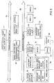
- Fig. 7 shows a hardware/software block diagram of the depth measurement processing.
- the cable movement measuring device (CMMD) 12 of Fig. 2 is gimbal mounted just outside the winch and is fixed in the roll axis.
- a wireline cable 15 is secured between two integrated depth measuring wheels 120 and 121 by means of cable guides and spring loaded rollers.
- On each wheel is a a rotary encoder 122,123 that measure the amount and direction of rotation, where two times ⁇ times the radius of each of the measuring wheels 120, 121 equals the amount of cable motion. Redundancy of measurement is provided because each of the encoders 120, 121 separately measures the amount and direction of rotation and the measurements from each CMMD measuring wheel 120, 121 are processed in parallel.
- the measurements from the measuring wheels 120, 121 comprising raw quadrature data are received by the quadrature pulse decoders 124,125 and are converted into incremental or decremental counts which are fed into motion accumulators 126,127, where one detectable motion of the measuring wheels 120, 121 corresponds to one accumulator count.
- the software begins motion processing 128, 129.
- the accumulator counts which correspond to motion increments or decrements over a sample period of time, are converted to a physical distance. Wheel correction for each wheel 128, 129, heave amount 131 (as measured by the MRU) and crank compensation 132 are applied, as necessary.
- Wheel correction 129, 130 compensates for changes in measuring wheel wear since as the measuring wheels are used the wheels wear so the radius of the wheel changes and a corresponding wheel correction must be applied. If a crank amount is pending 132, it is applied during the motion processing. Crank is a manual adjustment to the wireline cable that the winch engineer can enter to mechanically emulate a clutch assembly that was present in early winch systems. The engineer sets the amount of crank (change in the amount of wireline cable) and the electronics feed in the change to the winch uniformly and slowly over some period of cable motion. If heave compensation mode is selected, a heave measurement 131 that has been obtained from a motion reference unit is also applied. The output of the motion processing function 128, 129 is the net motion increment and cable speed.
- the net motion increment is calculated by subtracting the heave amount from the measured cable motion, where the measured cable motion is the logging tool motion plus the actual heave compensation applied by the winch control. Any cable slip detection and correction 135 is added to the net motion increment and the result is converted to depth in the encoder depth accumulators 133, 134. In the multiplexor 136, an algorithm is used to choose the best of the two estimates from both measuring wheels 120, 121 based on the measurement most advanced in direction of the wireline motion. The measured depth is then output to the logging system for recording, to the operator displays and to an alarm generation function.
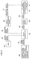
- Fig. 8 is a flowchart of the alarm generation function of the depth measurement system 150.
- An alarm is set 156 when the well logging tool is outside the transition region and the winch is not in the appropriate mode.
- a transition region is a designated length of the well in which it is safe for the heave motion compensation to be either on or off.
- the heave motion compensation is off and the tool is stopped the tool does not move with respect to the rig, but does move with respect to the well and the sea bed.
- With heave motion compensation on the tool moves with respect to the rig, but is stationary with respect to the formations in the well. Outsider of the transition region towards the surface, heave motion compensation should be turned off so that the tool may be safely handled on the rig floor.
- heave motion compensation should be turned on so that the tool motion, with respect to the formations in the well, is not affected by the rig motion. If the tool is above the transition region 151 and heave compensation is on 152, an alarm is set 156. If the tool is above the transition regions 151 and heave compensations 152 is off, the alarm is cleared 155. If the tool is below the transition region 153 and heave compensation is off 154, an alarm is set 156. If the tool is below the transition region 153 and heave compensation is active 154, the alarm is cleared 155. The alarm may then be displayed on the alarm and control display and may also be available for display on the winch control panel and display HMI.
- the winch may be operated in three modes of operation: manual mode (Fig. 9), cruise mode (Fig. 10) and heave compensated mode (Fig. 11).
- Fig. 10 shows a control flow diagram of the winch operation in cruise mode.
- the operator at the operator interface 170 inputs cable speed and cable tension commands 171.
- the measured cable speed and cable tension 172 is computed by the front end controller (FEC) within depth measurement system 173 using cable movement measuring device 179 measured cable motion and tension 180 and is transmitted to the winch controller.
- the winch controller 174 uses the cable speed and tension 171 input by the operator and the measured cable speed and tension 172, the winch controller 174 calculates and scales RPM/torque commands 175 and sends them to the winch motor drive 176, which in turn sends the RPM/torque commands to the winch motor 178.
Landscapes
- Engineering & Computer Science (AREA)
- Geology (AREA)
- Life Sciences & Earth Sciences (AREA)
- Mining & Mineral Resources (AREA)
- Mechanical Engineering (AREA)
- Environmental & Geological Engineering (AREA)
- Fluid Mechanics (AREA)
- General Life Sciences & Earth Sciences (AREA)
- Geochemistry & Mineralogy (AREA)
- Physics & Mathematics (AREA)
- Geophysics And Detection Of Objects (AREA)
- Earth Drilling (AREA)
- Electric Cable Installation (AREA)
- Vehicle Body Suspensions (AREA)
- Bridges Or Land Bridges (AREA)
- Testing Or Calibration Of Command Recording Devices (AREA)
- Excavating Of Shafts Or Tunnels (AREA)
- Control And Safety Of Cranes (AREA)
- Medicines Containing Material From Animals Or Micro-Organisms (AREA)
- Medicines Containing Plant Substances (AREA)
- Transplanting Machines (AREA)
- Details Of Flowmeters (AREA)
- Testing Of Balance (AREA)
- Length Measuring Devices With Unspecified Measuring Means (AREA)
- Devices For Conveying Motion By Means Of Endless Flexible Members (AREA)
- Pit Excavations, Shoring, Fill Or Stabilisation Of Slopes (AREA)
- Crystals, And After-Treatments Of Crystals (AREA)
Abstract
Description
- Fig. 1 is a diagram showing the heave compensated wireline logging winch system mounted on a floating vessel.
- Fig. 2 is a diagram of the winch of Fig. 1.
- Fig. 3 is a block diagram of the physical heave compensation system and the physical correction made by the winch.
- Fig. 4 is a system block diagram of the heave compensation wireline logging winch system.
- Fig. 5 is a network architecture diagram of the wireline winch controller with system and operator interfaces.
- Fig. 6 shows the layout of a typical wireline winch logging status display.
- Fig. 7 shows a hardware/software block diagram of the depth measurement processing.
- Fig. 8 is a flowchart of the alarm generation function of the depth measurement system.
- Fig. 9 shows a control flow diagram of the winch operation in manual mode.
- Fig. 10 shows a control flow diagram of the winch operation in cruise mode.
- Fig. 11 shows a flow control diagram of the winch operation in heave compensated mode.
Claims (20)
- A system for compensating for vertical motion of a floating vessel comprising:a winch control means for receiving vessel vertical motion data and logging tool speed set points;a wireline winch means for raising and lowering a wireline cable within a wellbore, connected to the winch control means and comprising a winch motor for attaching to and rotatably moving a cable drum, the wireline cable having at least one logging measurement tool attached to an end of the wireline cable extending from the cable drum; andthe winch control means for combining the vertical motion data and logging tool speed set points to produce a winch motor control signal for controlling the rotatable movement of the cable drum so as to cause the wireline cable to achieve movement within the wellbore at a controlled speed independent of vessel vertical motion.
- The system according to claim 1 further comprising the winch control means receives logging tool tension set points and combines the logging tool tension set points with the vertical motion data and logging tool speed set points to produce the winch motor control signal.
- The system according to any preceding claims further comprising:depth computing means for receiving the vessel vertical motion data and measured wireline cable motion data; andthe depth computing means for calculating a heave compensation depth error by combining the measured wireline cable motion data and the vessel vertical motion data.
- The system according to claim 4 wherein the heave compensation depth error is saved together with logging measurement tool data from the logging measurement tools.
- The system according to claim 2 wherein the vertical motion data comprises vessel vertical position, speed and acceleration.
- The system according to claim 4 further comprising an alarm generation means for producing an alarm signal.
- The system according to claim 6 wherein the alarm signal is displayed on an operator display console connected to the depth computing means.
- The system according to claim 4 wherein the operator enters the speed set point and the tension set point at an operator interface connected to the winch control means.
- The system according to claim 4 wherein the winch motor control signal comprises a RPM value and a torque value.
- The system according to claim 2 further comprising a first operator control and display means for entering operator commands, displaying winch system status and providing feedback to an operator of heave compensation status.
- The system according to claim 11 further comprising a second operator control and display means.
- A method of compensating for vertical motion of a floating vessel comprising:receiving vessel vertical motion data and logging tool speed set points by a winch control means;raising and lowering a wireline cable within a wellbore by a wireline winch means connected to the winch control means comprising a winch motor for attaching to and rotatably moving a cable drum, the wireline cable having at least one logging measurement tool attached to an end of the cable extending from the cable drum; andcombining the vertical motion data and logging tool speed set points by the winch control means to produce a winch motor control signal for controlling the rotatable movement of the cable drum so as to cause the wireline cable to achieve movement within the wellbore at a controlled speed independent of vessel vertical motion.
- The method according to claim 13 further comprising receiving logging tool tension set points and producing a winch motor control signal by combining the logging tool tension set points with the vertical motion data and logging tool speed set points.
- The method according to claim 13 or 14 further comprising:receiving vessel vertical motion data and measured wireline cable motion data at a depth computing means; andcalculating a heave compensation depth error by the depth computing means by combining the measured wireline cable motion data and the vessel vertical motion data.
- The method according to claim 15 wherein the vertical motion data comprises vessel vertical position, speed and acceleration.
- The method according to claim 15 or claim 16 further comprising saving the heave compensation depth error value together with logging measurement tool data.
- The method according to claim 17 further comprising compensating a depth measurement of the logging measurement tool data using the heave compensation depth error value.
- The method according to claim 15 wherein the receiving vertical motion data and combining the vertical motion data and logging tool speed and tension set points to produce a winch motor control signal by the winch control means occurs in real time.
- The method according to claim 15 further comprising producing an alarm signal by an alarm generation means when the logging tool is about to enter a position above the wellbore and/or about to contact a bottom of a well
- The method according to claim 16 further comprising entering operator commands, displaying winch system status and providing feedback to an operator of heave compensation status at an operator control and display means.
Applications Claiming Priority (2)
| Application Number | Priority Date | Filing Date | Title |
|---|---|---|---|
| US09/356,432 US6216789B1 (en) | 1999-07-19 | 1999-07-19 | Heave compensated wireline logging winch system and method of use |
| US356432 | 1999-07-19 |
Publications (3)
| Publication Number | Publication Date |
|---|---|
| EP1070828A2 true EP1070828A2 (en) | 2001-01-24 |
| EP1070828A3 EP1070828A3 (en) | 2002-02-27 |
| EP1070828B1 EP1070828B1 (en) | 2003-10-22 |
Family
ID=23401398
Family Applications (1)
| Application Number | Title | Priority Date | Filing Date |
|---|---|---|---|
| EP00202354A Expired - Lifetime EP1070828B1 (en) | 1999-07-19 | 2000-07-04 | Heave compensator |
Country Status (14)
| Country | Link |
|---|---|
| US (1) | US6216789B1 (en) |
| EP (1) | EP1070828B1 (en) |
| CN (1) | CN1273720C (en) |
| AT (1) | ATE252681T1 (en) |
| AU (1) | AU731132B2 (en) |
| BR (1) | BR0002943B1 (en) |
| CA (1) | CA2312515C (en) |
| CO (1) | CO5271764A1 (en) |
| DE (1) | DE60006040T2 (en) |
| DK (1) | DK1070828T3 (en) |
| EG (1) | EG22566A (en) |
| ID (1) | ID29218A (en) |
| MX (1) | MXPA00006633A (en) |
| NO (1) | NO319996B1 (en) |
Cited By (7)
| Publication number | Priority date | Publication date | Assignee | Title |
|---|---|---|---|---|
| GB2435278A (en) * | 2006-02-15 | 2007-08-22 | Schlumberger Holdings | Offshore coiled tubing heave compensation control system |
| WO2009066250A1 (en) * | 2007-11-20 | 2009-05-28 | Schlumberger Canada Limited | Electronic control for winch tension |
| NL2001656C2 (en) * | 2008-06-06 | 2009-06-08 | Itrec Bv | Hoisting device/hoisting crane for laying e.g. pipeline, on seabed during construction of e.g. underwater installation, has control unit compensating output signal of output unit based on measured joint diameter |
| WO2013101601A1 (en) * | 2011-12-29 | 2013-07-04 | Shell Oil Company | Method and system for wireline intervention in a subsea well from a floating vessel |
| EP3335977A1 (en) | 2016-12-15 | 2018-06-20 | Robert Bosch GmbH | Method and device for swell compensation |
| EP4112528A1 (en) * | 2021-07-02 | 2023-01-04 | Gilbert & Schmalriede GmbH & Co. KG | Method for regulating a cable traction of a cable winch of a watercraft and a corresponding compensator |
| CN121068255A (en) * | 2025-11-10 | 2025-12-05 | 武汉华中航空测控技术有限公司 | Marine intelligent test device |
Families Citing this family (59)
| Publication number | Priority date | Publication date | Assignee | Title |
|---|---|---|---|---|
| US7007751B2 (en) * | 2001-05-11 | 2006-03-07 | Eggleston Philip W | Apparatus for extracting oil or other fluids from a well |
| US6836707B2 (en) * | 2002-05-30 | 2004-12-28 | Honeywell International Inc. | Methods and systems for determining heave and heave rate of vessels |
| US7000903B2 (en) * | 2003-03-24 | 2006-02-21 | Oceaneering International, Inc. | Wireline subsea metering head and method of use |
| GB0406336D0 (en) * | 2004-03-19 | 2004-04-21 | Subsea 7 Uk | Apparatus and method |
| US7347256B1 (en) | 2005-08-01 | 2008-03-25 | Philip W Eggleston | Portable well fluid extraction apparatus |
| US7607478B2 (en) * | 2006-04-28 | 2009-10-27 | Schlumberger Technology Corporation | Intervention tool with operational parameter sensors |
| US8218826B2 (en) * | 2006-05-19 | 2012-07-10 | Schlumberger Technology Corporation | Integrated measurement based on an optical pattern-recognition |
| EP2054335B1 (en) * | 2006-08-15 | 2012-04-04 | Hydralift Amclyde, Inc. | Direct acting single sheave active/passiv heave compensator |
| WO2008068445A1 (en) * | 2006-12-06 | 2008-06-12 | National Oilwell Varco, L.P. | Method and apparatus for active heave compensation |
| US7688674B2 (en) * | 2007-03-05 | 2010-03-30 | Schlumberger Technology Corporation | Methods and apparatus for performing moving checkshots |
| GB0705110D0 (en) * | 2007-03-16 | 2007-04-25 | Lewis Ltd | Wireline intervention system |
| US8439109B2 (en) * | 2008-05-23 | 2013-05-14 | Schlumberger Technology Corporation | System and method for depth measurement and correction during subsea intervention operations |
| US8776711B2 (en) * | 2009-12-21 | 2014-07-15 | Eaton Corporation | Active heave compensation with active damping control |
| EP2516795A4 (en) | 2009-12-23 | 2017-03-22 | Schlumberger Technology B.V. | Hydraulic deployment of a well isolation mechanism |
| ES2426329T3 (en) * | 2010-12-20 | 2013-10-22 | Christopher Bauder | Winch to provide a predetermined length of unwound cable |
| CN102071875B (en) * | 2011-01-19 | 2013-09-04 | 中国海洋石油总公司 | Automatic control system for winch and control method of automatic control system |
| KR20140116386A (en) | 2011-12-30 | 2014-10-02 | 내셔널 오일웰 바르코 엘.피. | Deep water knuckle boom crane |
| US9528328B2 (en) * | 2012-01-31 | 2016-12-27 | Schlumberger Technology Corporation | Passive offshore tension compensator assembly |
| DE102012004803A1 (en) * | 2012-03-09 | 2013-09-12 | Liebherr-Werk Nenzing Gmbh | Crane control with drive limitation |
| DE102012004802A1 (en) * | 2012-03-09 | 2013-09-12 | Liebherr-Werk Nenzing Gmbh | Crane control with distribution of a kinematically limited size of the hoist |
| US9290362B2 (en) | 2012-12-13 | 2016-03-22 | National Oilwell Varco, L.P. | Remote heave compensation system |
| US9988248B2 (en) * | 2014-04-04 | 2018-06-05 | David R. Hall | Accurate position tracking for motorized lifting device |
| GB2530947B (en) * | 2013-09-27 | 2017-03-01 | Paradigm Tech Services B V | A tool and method for use within an elongated space |
| CA2838221C (en) | 2013-12-19 | 2022-02-22 | Rangeland Drilling Automation Inc. | Automated drilling/service rig apparatus |
| CN103696758B (en) * | 2013-12-24 | 2017-10-27 | 中国电子科技集团公司第二十二研究所 | Winch, drifting equipment and depth-logger measuring method |
| US20180297826A1 (en) * | 2014-06-20 | 2018-10-18 | Hoist All, Inc. | Portable hoist assembly system |
| GB201417272D0 (en) | 2014-09-30 | 2014-11-12 | Paradigm Technology Services B V | Measurement method and system |
| US10207905B2 (en) | 2015-02-05 | 2019-02-19 | Schlumberger Technology Corporation | Control system for winch and capstan |
| AU2016222872A1 (en) * | 2015-02-23 | 2017-10-12 | Transocean Sedco Forex Ventures Limited | Marine motion compensated draw-works real-time performance monitoring and prediction |
| WO2016148705A1 (en) * | 2015-03-17 | 2016-09-22 | Halliburton Energy Services, Inc. | Optimization of downhole logging tool data resolution |
| CN104742941B (en) * | 2015-04-08 | 2015-12-02 | 重庆广播电视大学 | Cable car target control speed arranges system |
| US11945558B2 (en) | 2015-04-16 | 2024-04-02 | Shmuel Sam Arditi | System and method for controlling motorzied boat fender deployment and retrieval systems |
| US11072402B2 (en) * | 2015-04-16 | 2021-07-27 | Shmuel Sam Arditi | Reduced-complexity fender positioning system and method |
| US9764808B2 (en) * | 2015-04-16 | 2017-09-19 | Shmuel Sam Arditi | Enhanced system and method for controlling automatic deployment of boat fenders |
| US9937985B2 (en) * | 2015-04-16 | 2018-04-10 | Shmuel Sam Arditi | System and method for planning and predetermination of fender heights and dock location information |
| CA2927822A1 (en) * | 2015-04-28 | 2016-10-28 | Option Industries Inc. | System and method for monitoring a winch |
| US9689215B2 (en) * | 2015-06-11 | 2017-06-27 | Reel Power Licensing Corp. | Self-adjusting reel assembly apparatus, system and method |
| US9714550B2 (en) * | 2015-06-11 | 2017-07-25 | Reel Power Licensing Corp. | Method for constant tension and slippage setting on a reel using proximity sensors to detect rotational direction |
| US10233705B2 (en) * | 2015-07-17 | 2019-03-19 | PATCO Machine & Fab., Inc. | Reel control systems with data logging |
| US10865068B2 (en) | 2019-04-23 | 2020-12-15 | PATCO Machine & Fab., Inc. | Electronically controlled reel systems including electric motors |
| US9206658B1 (en) | 2015-07-17 | 2015-12-08 | PATCO Machine & Fab., Inc. | Controlling cable spooling systems |
| US10268174B2 (en) | 2015-11-13 | 2019-04-23 | Hydril USA Distribution LLC | Automated reel control console |
| EP3226095A1 (en) | 2016-03-31 | 2017-10-04 | Fraunhofer-Gesellschaft zur Förderung der angewandten Forschung e.V. | System and method of navigation of an autonomously navigated submersible vehicle at entering a catch station |
| US10301892B2 (en) * | 2016-08-16 | 2019-05-28 | Baker Hughes, A Ge Company, Llc | Wireline performance profile analysis |
| CN107187963B (en) * | 2017-06-14 | 2019-08-23 | 北京中地英捷物探仪器研究所有限公司 | A kind of inserting tube for well logging is hampered monitoring system |
| US10443325B2 (en) | 2017-09-01 | 2019-10-15 | Schlumberger Technology Corporation | Method and system for pipe conveyed logging |
| US10633230B2 (en) * | 2018-04-10 | 2020-04-28 | Goodrich Corporation | Integrated hoist maintenance and method of hoist operation |
| GB2587134B (en) | 2018-04-23 | 2022-05-25 | Patco Machine & Fab Inc | Reel with power advance repositionable level wind |
| CN108897241B (en) * | 2018-06-25 | 2021-09-14 | 重庆华油实业有限公司 | Logging winch parameter acquisition and transmission system |
| WO2021072071A1 (en) * | 2019-10-08 | 2021-04-15 | Schlumberger Technology Corporation | Intelligent data acquisition for wireline logging |
| CN111305824B (en) * | 2020-03-27 | 2024-03-29 | 北京环鼎科技有限责任公司 | Depth interface panel capable of separating display and operation and application method thereof |
| CN112027952A (en) * | 2020-08-31 | 2020-12-04 | 中油国家油气钻井装备工程技术研究中心有限公司 | Oil rig winch control system with three operation modes and control method |
| US12454867B2 (en) | 2021-01-09 | 2025-10-28 | Gr Energy Services Management, Lp | Integrated wellsite processing system and wellsite monitoring system and method of using same |
| CN113093599A (en) * | 2021-03-30 | 2021-07-09 | 大庆宏测技术服务有限公司 | Intelligent control and monitoring system for logging truck |
| CN112964412B (en) * | 2021-04-15 | 2025-01-14 | 衡水市水利科学研究院 | A simple logging cable tension measurement and tension sudden change alarm device |
| MX2023008154A (en) | 2022-01-09 | 2023-07-21 | Gr Energy Services Man L P | Wellsite monitoring system with wellsite tracker and method of using same. |
| CN117092938A (en) * | 2022-05-13 | 2023-11-21 | 宝鸡宝石特种车辆有限责任公司 | Fully electric drive logging truck control system and control method |
| US12523138B2 (en) * | 2022-12-29 | 2026-01-13 | Halliburton Energy Services, Inc. | Autonomous start of pump-down operation |
| US12105481B1 (en) | 2023-03-15 | 2024-10-01 | Horizontal Wireline Services, Llc | System and method for automatic depth positioning of wire conveyed operations |
Family Cites Families (13)
| Publication number | Priority date | Publication date | Assignee | Title |
|---|---|---|---|---|
| US3001396A (en) * | 1958-02-14 | 1961-09-26 | James L Cleveland | Apparatus for maintaining proper depth correlation in well logging apparatus |
| US3259371A (en) * | 1964-09-18 | 1966-07-05 | Shell Oil Co | Wave cancellation system for a floating drilling vessel |
| GB1529331A (en) * | 1976-03-02 | 1978-10-18 | Clarke Chapman Ltd | Winding mechanism |
| US4157812A (en) * | 1977-08-15 | 1979-06-12 | Bunker Ramo Corporation | Ship motion compensator for recovery of oceanographic instrumentation |
| US4268013A (en) * | 1978-06-12 | 1981-05-19 | Nl Industries, Inc. | Crane motion compensator |
| US4349179A (en) * | 1979-06-19 | 1982-09-14 | Gec Mechanical Handling Limited | Control means for motion compensation devices |
| US4428421A (en) | 1981-09-14 | 1984-01-31 | H-G Testing Company | Wireline winch mounting system |
| US4547857A (en) * | 1983-06-23 | 1985-10-15 | Alexander George H | Apparatus and method for wave motion compensation and hoist control for marine winches |
| GB8328147D0 (en) | 1983-10-21 | 1983-11-23 | Vickers Plc | Marine heave compensating device |
| US4730677A (en) | 1986-12-22 | 1988-03-15 | Otis Engineering Corporation | Method and system for maintenance and servicing of subsea wells |
| US4932261A (en) | 1988-06-20 | 1990-06-12 | Triton Technologies, Inc. | Micro-machined accelerometer with tilt compensation |
| US4962817A (en) | 1989-04-03 | 1990-10-16 | A.R.M. Design Development | Active reference system |
| US5209302A (en) | 1991-10-04 | 1993-05-11 | Retsco, Inc. | Semi-active heave compensation system for marine vessels |
-
1999
- 1999-07-19 US US09/356,432 patent/US6216789B1/en not_active Expired - Lifetime
-
2000
- 2000-06-27 CA CA002312515A patent/CA2312515C/en not_active Expired - Lifetime
- 2000-06-27 AU AU42705/00A patent/AU731132B2/en not_active Ceased
- 2000-07-04 EP EP00202354A patent/EP1070828B1/en not_active Expired - Lifetime
- 2000-07-04 DK DK00202354T patent/DK1070828T3/en active
- 2000-07-04 AT AT00202354T patent/ATE252681T1/en not_active IP Right Cessation
- 2000-07-04 DE DE60006040T patent/DE60006040T2/en not_active Expired - Lifetime
- 2000-07-05 MX MXPA00006633A patent/MXPA00006633A/en active IP Right Grant
- 2000-07-12 ID IDP20000584D patent/ID29218A/en unknown
- 2000-07-14 CO CO00052939A patent/CO5271764A1/en not_active Application Discontinuation
- 2000-07-16 EG EG20000913A patent/EG22566A/en active
- 2000-07-18 NO NO20003672A patent/NO319996B1/en not_active IP Right Cessation
- 2000-07-18 BR BRPI0002943-2A patent/BR0002943B1/en not_active IP Right Cessation
- 2000-07-19 CN CNB001202944A patent/CN1273720C/en not_active Expired - Fee Related
Cited By (14)
| Publication number | Priority date | Publication date | Assignee | Title |
|---|---|---|---|---|
| GB2435278A (en) * | 2006-02-15 | 2007-08-22 | Schlumberger Holdings | Offshore coiled tubing heave compensation control system |
| GB2435278B (en) * | 2006-02-15 | 2009-02-18 | Schlumberger Holdings | Offshore coiled tubing heave compensation control system |
| WO2009066250A1 (en) * | 2007-11-20 | 2009-05-28 | Schlumberger Canada Limited | Electronic control for winch tension |
| US7900893B2 (en) | 2007-11-20 | 2011-03-08 | Schlumberger Technology Corporation | Electronic control for winch tension |
| NL2001656C2 (en) * | 2008-06-06 | 2009-06-08 | Itrec Bv | Hoisting device/hoisting crane for laying e.g. pipeline, on seabed during construction of e.g. underwater installation, has control unit compensating output signal of output unit based on measured joint diameter |
| GB2511450A (en) * | 2011-12-29 | 2014-09-03 | Shell Int Research | Method and system for wireline intervention in a subsea well from a floating vessel |
| WO2013101601A1 (en) * | 2011-12-29 | 2013-07-04 | Shell Oil Company | Method and system for wireline intervention in a subsea well from a floating vessel |
| AU2012362727B2 (en) * | 2011-12-29 | 2016-02-18 | Shell Internationale Research Maatschappij B.V. | Method and system for wireline intervention in a subsea well from a floating vessel |
| GB2511450B (en) * | 2011-12-29 | 2017-08-09 | Shell Int Research | Method and system for wireline intervention in a subsea well from a floating vessel |
| US10240407B2 (en) | 2011-12-29 | 2019-03-26 | Shell Oil Company | Method and system for wireline intervention in a subsea well from a floating vessel |
| EP3335977A1 (en) | 2016-12-15 | 2018-06-20 | Robert Bosch GmbH | Method and device for swell compensation |
| DE102016225093A1 (en) | 2016-12-15 | 2018-06-21 | Robert Bosch Gmbh | Method and device for wave compensation |
| EP4112528A1 (en) * | 2021-07-02 | 2023-01-04 | Gilbert & Schmalriede GmbH & Co. KG | Method for regulating a cable traction of a cable winch of a watercraft and a corresponding compensator |
| CN121068255A (en) * | 2025-11-10 | 2025-12-05 | 武汉华中航空测控技术有限公司 | Marine intelligent test device |
Also Published As
| Publication number | Publication date |
|---|---|
| AU4270500A (en) | 2001-01-25 |
| ATE252681T1 (en) | 2003-11-15 |
| NO20003672L (en) | 2001-01-22 |
| DE60006040D1 (en) | 2003-11-27 |
| CO5271764A1 (en) | 2003-04-30 |
| CA2312515C (en) | 2004-11-02 |
| EG22566A (en) | 2003-04-30 |
| NO20003672D0 (en) | 2000-07-18 |
| CA2312515A1 (en) | 2001-01-19 |
| CN1273720C (en) | 2006-09-06 |
| NO319996B1 (en) | 2005-10-10 |
| MXPA00006633A (en) | 2002-03-15 |
| BR0002943A (en) | 2001-04-03 |
| EP1070828B1 (en) | 2003-10-22 |
| AU731132B2 (en) | 2001-03-22 |
| BR0002943B1 (en) | 2011-10-04 |
| ID29218A (en) | 2001-08-16 |
| DK1070828T3 (en) | 2004-03-01 |
| DE60006040T2 (en) | 2004-07-08 |
| CN1281089A (en) | 2001-01-24 |
| EP1070828A3 (en) | 2002-02-27 |
| US6216789B1 (en) | 2001-04-17 |
Similar Documents
| Publication | Publication Date | Title |
|---|---|---|
| US6216789B1 (en) | Heave compensated wireline logging winch system and method of use | |
| US9650880B2 (en) | Waveform anti-stick slip system and method | |
| US8265811B2 (en) | Method and apparatus for active heave compensation | |
| US5107705A (en) | Video system and method for determining and monitoring the depth of a bottomhole assembly within a wellbore | |
| US20030234119A1 (en) | Well drilling control system | |
| US7363988B2 (en) | System and method for processing and transmitting information from measurements made while drilling | |
| CA2525382C (en) | Method of and system for directional drilling | |
| CA2511678C (en) | Automated control system for back-reaming | |
| US9404307B2 (en) | Method and system for directional drilling | |
| CA2578172C (en) | Offshore coiled tubing heave compensation control system | |
| MXPA05006330A (en) | Method of and apparatus for directional drilling. | |
| US5274552A (en) | Drill string motion detection for bit depth calculation | |
| AU2019210842B2 (en) | Drilling apparatus and method for the determination of formation location | |
| US4852052A (en) | Kelly-to-riser position determining system with adjustment for uncompensated heave | |
| EA010755B1 (en) | Wureline subsea metering head and method of use | |
| GB2383146A (en) | Method for correlating well logs | |
| US4951505A (en) | Block position sensor | |
| NO20110215A1 (en) | Apparatus and method for generating sector affiliation for downhole time images | |
| WO2020154052A1 (en) | System and method to determine fatigue life of drilling components | |
| CN117536570A (en) | Intelligent directional coring system | |
| US20210017848A1 (en) | Collar control system for mobile drilling machines | |
| CN221322381U (en) | Semi-submersible drilling platform logging depth compensation system | |
| AU2020205242B2 (en) | Collar control system for mobile drilling machines | |
| JP2562859B2 (en) | Weight synchronization device in absolute position measuring device for underground wall excavator | |
| CN116025329A (en) | A Direct Measurement Method of the Absolute Height of the Swimming Crane System of Drilling Rig |
Legal Events
| Date | Code | Title | Description |
|---|---|---|---|
| PUAI | Public reference made under article 153(3) epc to a published international application that has entered the european phase |
Free format text: ORIGINAL CODE: 0009012 |
|
| AK | Designated contracting states |
Kind code of ref document: A2 Designated state(s): AT BE CH CY DE DK ES FI FR GB GR IE IT LI LU MC NL PT SE |
|
| AX | Request for extension of the european patent |
Free format text: AL;LT;LV;MK;RO;SI |
|
| PUAL | Search report despatched |
Free format text: ORIGINAL CODE: 0009013 |
|
| AK | Designated contracting states |
Kind code of ref document: A3 Designated state(s): AT BE CH CY DE DK ES FI FR GB GR IE IT LI LU MC NL PT SE |
|
| AX | Request for extension of the european patent |
Free format text: AL;LT;LV;MK;RO;SI |
|
| 17P | Request for examination filed |
Effective date: 20020722 |
|
| AKX | Designation fees paid |
Free format text: AT BE CH CY DE DK ES FI FR GB GR IE IT LI LU MC NL PT SE |
|
| 17Q | First examination report despatched |
Effective date: 20021010 |
|
| GRAH | Despatch of communication of intention to grant a patent |
Free format text: ORIGINAL CODE: EPIDOS IGRA |
|
| GRAS | Grant fee paid |
Free format text: ORIGINAL CODE: EPIDOSNIGR3 |
|
| GRAA | (expected) grant |
Free format text: ORIGINAL CODE: 0009210 |
|
| AK | Designated contracting states |
Kind code of ref document: B1 Designated state(s): AT BE CH CY DE DK ES FI FR GB GR IE IT LI LU MC NL PT SE |
|
| PG25 | Lapsed in a contracting state [announced via postgrant information from national office to epo] |
Ref country code: CH Free format text: LAPSE BECAUSE OF FAILURE TO SUBMIT A TRANSLATION OF THE DESCRIPTION OR TO PAY THE FEE WITHIN THE PRESCRIBED TIME-LIMIT Effective date: 20031022 Ref country code: FI Free format text: LAPSE BECAUSE OF FAILURE TO SUBMIT A TRANSLATION OF THE DESCRIPTION OR TO PAY THE FEE WITHIN THE PRESCRIBED TIME-LIMIT Effective date: 20031022 Ref country code: CY Free format text: LAPSE BECAUSE OF FAILURE TO SUBMIT A TRANSLATION OF THE DESCRIPTION OR TO PAY THE FEE WITHIN THE PRESCRIBED TIME-LIMIT Effective date: 20031022 Ref country code: BE Free format text: LAPSE BECAUSE OF FAILURE TO SUBMIT A TRANSLATION OF THE DESCRIPTION OR TO PAY THE FEE WITHIN THE PRESCRIBED TIME-LIMIT Effective date: 20031022 Ref country code: AT Free format text: LAPSE BECAUSE OF FAILURE TO SUBMIT A TRANSLATION OF THE DESCRIPTION OR TO PAY THE FEE WITHIN THE PRESCRIBED TIME-LIMIT Effective date: 20031022 Ref country code: LI Free format text: LAPSE BECAUSE OF FAILURE TO SUBMIT A TRANSLATION OF THE DESCRIPTION OR TO PAY THE FEE WITHIN THE PRESCRIBED TIME-LIMIT Effective date: 20031022 |
|
| REG | Reference to a national code |
Ref country code: GB Ref legal event code: FG4D |
|
| REG | Reference to a national code |
Ref country code: CH Ref legal event code: EP |
|
| REG | Reference to a national code |
Ref country code: IE Ref legal event code: FG4D |
|
| REF | Corresponds to: |
Ref document number: 60006040 Country of ref document: DE Date of ref document: 20031127 Kind code of ref document: P |
|
| PG25 | Lapsed in a contracting state [announced via postgrant information from national office to epo] |
Ref country code: SE Free format text: LAPSE BECAUSE OF FAILURE TO SUBMIT A TRANSLATION OF THE DESCRIPTION OR TO PAY THE FEE WITHIN THE PRESCRIBED TIME-LIMIT Effective date: 20040122 Ref country code: GR Free format text: LAPSE BECAUSE OF FAILURE TO SUBMIT A TRANSLATION OF THE DESCRIPTION OR TO PAY THE FEE WITHIN THE PRESCRIBED TIME-LIMIT Effective date: 20040122 |
|
| PG25 | Lapsed in a contracting state [announced via postgrant information from national office to epo] |
Ref country code: ES Free format text: LAPSE BECAUSE OF FAILURE TO SUBMIT A TRANSLATION OF THE DESCRIPTION OR TO PAY THE FEE WITHIN THE PRESCRIBED TIME-LIMIT Effective date: 20040202 |
|
| REG | Reference to a national code |
Ref country code: DK Ref legal event code: T3 |
|
| REG | Reference to a national code |
Ref country code: CH Ref legal event code: PL |
|
| PG25 | Lapsed in a contracting state [announced via postgrant information from national office to epo] |
Ref country code: LU Free format text: LAPSE BECAUSE OF NON-PAYMENT OF DUE FEES Effective date: 20040704 |
|
| PG25 | Lapsed in a contracting state [announced via postgrant information from national office to epo] |
Ref country code: MC Free format text: LAPSE BECAUSE OF NON-PAYMENT OF DUE FEES Effective date: 20040731 |
|
| ET | Fr: translation filed | ||
| PLBE | No opposition filed within time limit |
Free format text: ORIGINAL CODE: 0009261 |
|
| STAA | Information on the status of an ep patent application or granted ep patent |
Free format text: STATUS: NO OPPOSITION FILED WITHIN TIME LIMIT |
|
| 26N | No opposition filed |
Effective date: 20040723 |
|
| PG25 | Lapsed in a contracting state [announced via postgrant information from national office to epo] |
Ref country code: PT Free format text: LAPSE BECAUSE OF NON-PAYMENT OF DUE FEES Effective date: 20040322 |
|
| REG | Reference to a national code |
Ref country code: FR Ref legal event code: PLFP Year of fee payment: 17 |
|
| REG | Reference to a national code |
Ref country code: FR Ref legal event code: PLFP Year of fee payment: 18 |
|
| REG | Reference to a national code |
Ref country code: FR Ref legal event code: PLFP Year of fee payment: 19 |
|
| PGFP | Annual fee paid to national office [announced via postgrant information from national office to epo] |
Ref country code: IE Payment date: 20180726 Year of fee payment: 19 Ref country code: IT Payment date: 20180725 Year of fee payment: 19 |
|
| PGFP | Annual fee paid to national office [announced via postgrant information from national office to epo] |
Ref country code: GB Payment date: 20180731 Year of fee payment: 19 Ref country code: DK Payment date: 20180725 Year of fee payment: 19 |
|
| PGFP | Annual fee paid to national office [announced via postgrant information from national office to epo] |
Ref country code: DE Payment date: 20180928 Year of fee payment: 19 |
|
| PGFP | Annual fee paid to national office [announced via postgrant information from national office to epo] |
Ref country code: NL Payment date: 20190612 Year of fee payment: 20 |
|
| PGFP | Annual fee paid to national office [announced via postgrant information from national office to epo] |
Ref country code: FR Payment date: 20190604 Year of fee payment: 20 |
|
| REG | Reference to a national code |
Ref country code: DE Ref legal event code: R119 Ref document number: 60006040 Country of ref document: DE |
|
| REG | Reference to a national code |
Ref country code: DK Ref legal event code: EBP Effective date: 20190731 |
|
| GBPC | Gb: european patent ceased through non-payment of renewal fee |
Effective date: 20190704 |
|
| PG25 | Lapsed in a contracting state [announced via postgrant information from national office to epo] |
Ref country code: GB Free format text: LAPSE BECAUSE OF NON-PAYMENT OF DUE FEES Effective date: 20190704 Ref country code: DE Free format text: LAPSE BECAUSE OF NON-PAYMENT OF DUE FEES Effective date: 20200201 |
|
| REG | Reference to a national code |
Ref country code: NL Ref legal event code: MK Effective date: 20200703 |
|
| PG25 | Lapsed in a contracting state [announced via postgrant information from national office to epo] |
Ref country code: IE Free format text: LAPSE BECAUSE OF NON-PAYMENT OF DUE FEES Effective date: 20190704 Ref country code: DK Free format text: LAPSE BECAUSE OF NON-PAYMENT OF DUE FEES Effective date: 20190731 |
|
| PG25 | Lapsed in a contracting state [announced via postgrant information from national office to epo] |
Ref country code: IT Free format text: LAPSE BECAUSE OF NON-PAYMENT OF DUE FEES Effective date: 20190704 |