EP1069475A1 - Flexographic printing element comprising an IR-ablatable layer with high sensitivity - Google Patents
Flexographic printing element comprising an IR-ablatable layer with high sensitivity Download PDFInfo
- Publication number
- EP1069475A1 EP1069475A1 EP00114256A EP00114256A EP1069475A1 EP 1069475 A1 EP1069475 A1 EP 1069475A1 EP 00114256 A EP00114256 A EP 00114256A EP 00114256 A EP00114256 A EP 00114256A EP 1069475 A1 EP1069475 A1 EP 1069475A1
- Authority
- EP
- European Patent Office
- Prior art keywords
- layer
- printing element
- ablatable layer
- ablatable
- flexographic printing
- Prior art date
- Legal status (The legal status is an assumption and is not a legal conclusion. Google has not performed a legal analysis and makes no representation as to the accuracy of the status listed.)
- Granted
Links
- 238000007639 printing Methods 0.000 title claims abstract description 67
- 230000035945 sensitivity Effects 0.000 title description 8
- 239000011230 binding agent Substances 0.000 claims abstract description 36
- -1 aliphatic diester Chemical class 0.000 claims abstract description 25
- 230000005855 radiation Effects 0.000 claims abstract description 15
- 238000005516 engineering process Methods 0.000 claims abstract description 13
- 238000000034 method Methods 0.000 claims abstract description 13
- 239000011358 absorbing material Substances 0.000 claims abstract description 12
- 239000006229 carbon black Substances 0.000 claims description 12
- 239000004615 ingredient Substances 0.000 claims description 11
- 150000001875 compounds Chemical class 0.000 claims description 4
- 239000000463 material Substances 0.000 claims description 4
- 125000002496 methyl group Chemical group [H]C([H])([H])* 0.000 claims description 4
- 229910002651 NO3 Inorganic materials 0.000 claims description 3
- 125000000217 alkyl group Chemical group 0.000 claims description 3
- 125000004432 carbon atom Chemical group C* 0.000 claims description 3
- 229920002678 cellulose Polymers 0.000 claims description 3
- 239000001913 cellulose Substances 0.000 claims description 3
- 229920003086 cellulose ether Polymers 0.000 claims description 3
- 230000001678 irradiating effect Effects 0.000 claims description 2
- 125000000449 nitro group Chemical group [O-][N+](*)=O 0.000 claims description 2
- 239000010410 layer Substances 0.000 description 110
- 235000019241 carbon black Nutrition 0.000 description 11
- 230000001681 protective effect Effects 0.000 description 10
- LYCAIKOWRPUZTN-UHFFFAOYSA-N Ethylene glycol Chemical compound OCCO LYCAIKOWRPUZTN-UHFFFAOYSA-N 0.000 description 8
- 150000005690 diesters Chemical class 0.000 description 8
- 239000006185 dispersion Substances 0.000 description 8
- 238000003384 imaging method Methods 0.000 description 8
- 229920000139 polyethylene terephthalate Polymers 0.000 description 8
- 239000005020 polyethylene terephthalate Substances 0.000 description 8
- 229920000642 polymer Polymers 0.000 description 8
- 239000011248 coating agent Substances 0.000 description 7
- 238000000576 coating method Methods 0.000 description 7
- 239000000975 dye Substances 0.000 description 7
- 239000004014 plasticizer Substances 0.000 description 7
- 239000002904 solvent Substances 0.000 description 7
- NIXOWILDQLNWCW-UHFFFAOYSA-M Acrylate Chemical compound [O-]C(=O)C=C NIXOWILDQLNWCW-UHFFFAOYSA-M 0.000 description 6
- 239000000020 Nitrocellulose Substances 0.000 description 6
- FJWGYAHXMCUOOM-QHOUIDNNSA-N [(2s,3r,4s,5r,6r)-2-[(2r,3r,4s,5r,6s)-4,5-dinitrooxy-2-(nitrooxymethyl)-6-[(2r,3r,4s,5r,6s)-4,5,6-trinitrooxy-2-(nitrooxymethyl)oxan-3-yl]oxyoxan-3-yl]oxy-3,5-dinitrooxy-6-(nitrooxymethyl)oxan-4-yl] nitrate Chemical class O([C@@H]1O[C@@H]([C@H]([C@H](O[N+]([O-])=O)[C@H]1O[N+]([O-])=O)O[C@H]1[C@@H]([C@@H](O[N+]([O-])=O)[C@H](O[N+]([O-])=O)[C@@H](CO[N+]([O-])=O)O1)O[N+]([O-])=O)CO[N+](=O)[O-])[C@@H]1[C@@H](CO[N+]([O-])=O)O[C@@H](O[N+]([O-])=O)[C@H](O[N+]([O-])=O)[C@H]1O[N+]([O-])=O FJWGYAHXMCUOOM-QHOUIDNNSA-N 0.000 description 6
- 229920001220 nitrocellulos Polymers 0.000 description 6
- OKTJSMMVPCPJKN-UHFFFAOYSA-N Carbon Chemical compound [C] OKTJSMMVPCPJKN-UHFFFAOYSA-N 0.000 description 5
- 239000004952 Polyamide Substances 0.000 description 5
- 239000000654 additive Substances 0.000 description 5
- 239000000203 mixture Substances 0.000 description 5
- 239000000178 monomer Substances 0.000 description 5
- 230000003287 optical effect Effects 0.000 description 5
- 239000000049 pigment Substances 0.000 description 5
- 229920002647 polyamide Polymers 0.000 description 5
- ZWEHNKRNPOVVGH-UHFFFAOYSA-N 2-Butanone Chemical compound CCC(C)=O ZWEHNKRNPOVVGH-UHFFFAOYSA-N 0.000 description 4
- 229920002799 BoPET Polymers 0.000 description 4
- 239000002270 dispersing agent Substances 0.000 description 4
- 239000004698 Polyethylene Substances 0.000 description 3
- 239000004793 Polystyrene Substances 0.000 description 3
- DNIAPMSPPWPWGF-UHFFFAOYSA-N Propylene glycol Chemical compound CC(O)CO DNIAPMSPPWPWGF-UHFFFAOYSA-N 0.000 description 3
- 238000002679 ablation Methods 0.000 description 3
- ISAOCJYIOMOJEB-UHFFFAOYSA-N benzoin Chemical compound C=1C=CC=CC=1C(O)C(=O)C1=CC=CC=C1 ISAOCJYIOMOJEB-UHFFFAOYSA-N 0.000 description 3
- 229920001400 block copolymer Polymers 0.000 description 3
- 229920001577 copolymer Polymers 0.000 description 3
- 125000003136 n-heptyl group Chemical group [H]C([H])([H])C([H])([H])C([H])([H])C([H])([H])C([H])([H])C([H])([H])C([H])([H])* 0.000 description 3
- 229920000573 polyethylene Polymers 0.000 description 3
- 229920002223 polystyrene Polymers 0.000 description 3
- 238000002360 preparation method Methods 0.000 description 3
- 229920002134 Carboxymethyl cellulose Polymers 0.000 description 2
- 229920002153 Hydroxypropyl cellulose Polymers 0.000 description 2
- UQSXHKLRYXJYBZ-UHFFFAOYSA-N Iron oxide Chemical compound [Fe]=O UQSXHKLRYXJYBZ-UHFFFAOYSA-N 0.000 description 2
- 239000006096 absorbing agent Substances 0.000 description 2
- 239000002253 acid Substances 0.000 description 2
- 150000001298 alcohols Chemical class 0.000 description 2
- QVGXLLKOCUKJST-UHFFFAOYSA-N atomic oxygen Chemical compound [O] QVGXLLKOCUKJST-UHFFFAOYSA-N 0.000 description 2
- 230000008901 benefit Effects 0.000 description 2
- 239000001768 carboxy methyl cellulose Substances 0.000 description 2
- 235000010948 carboxy methyl cellulose Nutrition 0.000 description 2
- 239000008112 carboxymethyl-cellulose Substances 0.000 description 2
- 239000003795 chemical substances by application Substances 0.000 description 2
- 230000000052 comparative effect Effects 0.000 description 2
- 150000001993 dienes Chemical class 0.000 description 2
- 238000009792 diffusion process Methods 0.000 description 2
- 230000032050 esterification Effects 0.000 description 2
- 238000005886 esterification reaction Methods 0.000 description 2
- 150000002148 esters Chemical class 0.000 description 2
- 230000008020 evaporation Effects 0.000 description 2
- 238000001704 evaporation Methods 0.000 description 2
- 239000001863 hydroxypropyl cellulose Substances 0.000 description 2
- 238000004519 manufacturing process Methods 0.000 description 2
- 150000002734 metacrylic acid derivatives Chemical class 0.000 description 2
- 125000000740 n-pentyl group Chemical group [H]C([H])([H])C([H])([H])C([H])([H])C([H])([H])C([H])([H])* 0.000 description 2
- 150000002823 nitrates Chemical class 0.000 description 2
- 229910052760 oxygen Inorganic materials 0.000 description 2
- 239000001301 oxygen Substances 0.000 description 2
- 239000002245 particle Substances 0.000 description 2
- 229920003207 poly(ethylene-2,6-naphthalate) Polymers 0.000 description 2
- 229920000058 polyacrylate Polymers 0.000 description 2
- 239000011112 polyethylene naphthalate Substances 0.000 description 2
- 239000002356 single layer Substances 0.000 description 2
- 239000004094 surface-active agent Substances 0.000 description 2
- RKJGQMJOEDIVQQ-UHFFFAOYSA-N (2,4-dinitrophenyl) prop-2-enoate Chemical compound [O-][N+](=O)C1=CC=C(OC(=O)C=C)C([N+]([O-])=O)=C1 RKJGQMJOEDIVQQ-UHFFFAOYSA-N 0.000 description 1
- PSRGGEQXKSZPRF-UHFFFAOYSA-N (4-nitrophenyl) prop-2-enoate Chemical compound [O-][N+](=O)C1=CC=C(OC(=O)C=C)C=C1 PSRGGEQXKSZPRF-UHFFFAOYSA-N 0.000 description 1
- QGKMIGUHVLGJBR-UHFFFAOYSA-M (4z)-1-(3-methylbutyl)-4-[[1-(3-methylbutyl)quinolin-1-ium-4-yl]methylidene]quinoline;iodide Chemical class [I-].C12=CC=CC=C2N(CCC(C)C)C=CC1=CC1=CC=[N+](CCC(C)C)C2=CC=CC=C12 QGKMIGUHVLGJBR-UHFFFAOYSA-M 0.000 description 1
- UCTWMZQNUQWSLP-VIFPVBQESA-N (R)-adrenaline Chemical compound CNC[C@H](O)C1=CC=C(O)C(O)=C1 UCTWMZQNUQWSLP-VIFPVBQESA-N 0.000 description 1
- JSOGDEOQBIUNTR-UHFFFAOYSA-N 2-(azidomethyl)oxirane Chemical compound [N-]=[N+]=NCC1CO1 JSOGDEOQBIUNTR-UHFFFAOYSA-N 0.000 description 1
- WPMUZECMAFLDQO-UHFFFAOYSA-N 2-[2-(2-hexanoyloxyethoxy)ethoxy]ethyl hexanoate Chemical compound CCCCCC(=O)OCCOCCOCCOC(=O)CCCCC WPMUZECMAFLDQO-UHFFFAOYSA-N 0.000 description 1
- YJGHMLJGPSVSLF-UHFFFAOYSA-N 2-[2-(2-octanoyloxyethoxy)ethoxy]ethyl octanoate Chemical compound CCCCCCCC(=O)OCCOCCOCCOC(=O)CCCCCCC YJGHMLJGPSVSLF-UHFFFAOYSA-N 0.000 description 1
- CWSZBVAUYPTXTG-UHFFFAOYSA-N 5-[6-[[3,4-dihydroxy-6-(hydroxymethyl)-5-methoxyoxan-2-yl]oxymethyl]-3,4-dihydroxy-5-[4-hydroxy-3-(2-hydroxyethoxy)-6-(hydroxymethyl)-5-methoxyoxan-2-yl]oxyoxan-2-yl]oxy-6-(hydroxymethyl)-2-methyloxane-3,4-diol Chemical compound O1C(CO)C(OC)C(O)C(O)C1OCC1C(OC2C(C(O)C(OC)C(CO)O2)OCCO)C(O)C(O)C(OC2C(OC(C)C(O)C2O)CO)O1 CWSZBVAUYPTXTG-UHFFFAOYSA-N 0.000 description 1
- 229920002126 Acrylic acid copolymer Polymers 0.000 description 1
- 239000004801 Chlorinated PVC Substances 0.000 description 1
- LFQSCWFLJHTTHZ-UHFFFAOYSA-N Ethanol Chemical compound CCO LFQSCWFLJHTTHZ-UHFFFAOYSA-N 0.000 description 1
- 239000001856 Ethyl cellulose Substances 0.000 description 1
- ZZSNKZQZMQGXPY-UHFFFAOYSA-N Ethyl cellulose Chemical compound CCOCC1OC(OC)C(OCC)C(OCC)C1OC1C(O)C(O)C(OC)C(CO)O1 ZZSNKZQZMQGXPY-UHFFFAOYSA-N 0.000 description 1
- 239000004716 Ethylene/acrylic acid copolymer Substances 0.000 description 1
- WHNWPMSKXPGLAX-UHFFFAOYSA-N N-Vinyl-2-pyrrolidone Chemical compound C=CN1CCCC1=O WHNWPMSKXPGLAX-UHFFFAOYSA-N 0.000 description 1
- 244000028419 Styrax benzoin Species 0.000 description 1
- 235000000126 Styrax benzoin Nutrition 0.000 description 1
- 235000008411 Sumatra benzointree Nutrition 0.000 description 1
- WGLPBDUCMAPZCE-UHFFFAOYSA-N Trioxochromium Chemical compound O=[Cr](=O)=O WGLPBDUCMAPZCE-UHFFFAOYSA-N 0.000 description 1
- QYKIQEUNHZKYBP-UHFFFAOYSA-N Vinyl ether Chemical class C=COC=C QYKIQEUNHZKYBP-UHFFFAOYSA-N 0.000 description 1
- 238000010521 absorption reaction Methods 0.000 description 1
- 239000000619 acesulfame-K Substances 0.000 description 1
- 150000001252 acrylic acid derivatives Chemical class 0.000 description 1
- 239000012790 adhesive layer Substances 0.000 description 1
- 239000002390 adhesive tape Substances 0.000 description 1
- 230000002411 adverse Effects 0.000 description 1
- 239000003963 antioxidant agent Substances 0.000 description 1
- 239000003125 aqueous solvent Substances 0.000 description 1
- 238000005452 bending Methods 0.000 description 1
- 229960002130 benzoin Drugs 0.000 description 1
- 239000003738 black carbon Substances 0.000 description 1
- 125000000484 butyl group Chemical group [H]C([*])([H])C([H])([H])C([H])([H])C([H])([H])[H] 0.000 description 1
- 229910000423 chromium oxide Inorganic materials 0.000 description 1
- 238000002485 combustion reaction Methods 0.000 description 1
- 239000000470 constituent Substances 0.000 description 1
- 238000007796 conventional method Methods 0.000 description 1
- IPHJYJHJDIGARM-UHFFFAOYSA-M copper phthalocyaninesulfonic acid, dioctadecyldimethylammonium salt Chemical compound [Cu+2].CCCCCCCCCCCCCCCCCC[N+](C)(C)CCCCCCCCCCCCCCCCCC.C=1C(S(=O)(=O)[O-])=CC=C(C(=NC2=NC(C3=CC=CC=C32)=N2)[N-]3)C=1C3=NC([C]1C=CC=CC1=1)=NC=1N=C1[C]3C=CC=CC3=C2[N-]1 IPHJYJHJDIGARM-UHFFFAOYSA-M 0.000 description 1
- 125000003438 dodecyl group Chemical group [H]C([H])([H])C([H])([H])C([H])([H])C([H])([H])C([H])([H])C([H])([H])C([H])([H])C([H])([H])C([H])([H])C([H])([H])C([H])([H])C([H])([H])* 0.000 description 1
- 238000001035 drying Methods 0.000 description 1
- 230000002708 enhancing effect Effects 0.000 description 1
- HQQADJVZYDDRJT-UHFFFAOYSA-N ethene;prop-1-ene Chemical group C=C.CC=C HQQADJVZYDDRJT-UHFFFAOYSA-N 0.000 description 1
- HSOOVEKLGOIEFF-UHFFFAOYSA-N ethenyl nitrate Chemical compound [O-][N+](=O)OC=C HSOOVEKLGOIEFF-UHFFFAOYSA-N 0.000 description 1
- 125000001495 ethyl group Chemical group [H]C([H])([H])C([H])([H])* 0.000 description 1
- 235000010944 ethyl methyl cellulose Nutrition 0.000 description 1
- 230000007717 exclusion Effects 0.000 description 1
- 239000000945 filler Substances 0.000 description 1
- 229920000578 graft copolymer Polymers 0.000 description 1
- 229910002804 graphite Inorganic materials 0.000 description 1
- 239000010439 graphite Substances 0.000 description 1
- 235000019382 gum benzoic Nutrition 0.000 description 1
- 229930195733 hydrocarbon Natural products 0.000 description 1
- 150000002430 hydrocarbons Chemical class 0.000 description 1
- WGCNASOHLSPBMP-UHFFFAOYSA-N hydroxyacetaldehyde Natural products OCC=O WGCNASOHLSPBMP-UHFFFAOYSA-N 0.000 description 1
- 235000019447 hydroxyethyl cellulose Nutrition 0.000 description 1
- 235000010977 hydroxypropyl cellulose Nutrition 0.000 description 1
- 239000003112 inhibitor Substances 0.000 description 1
- 239000001023 inorganic pigment Substances 0.000 description 1
- 125000000959 isobutyl group Chemical group [H]C([H])([H])C([H])(C([H])([H])[H])C([H])([H])* 0.000 description 1
- 125000001449 isopropyl group Chemical group [H]C([H])([H])C([H])(*)C([H])([H])[H] 0.000 description 1
- 238000003475 lamination Methods 0.000 description 1
- 238000002844 melting Methods 0.000 description 1
- 230000008018 melting Effects 0.000 description 1
- DZVCFNFOPIZQKX-LTHRDKTGSA-M merocyanine Chemical compound [Na+].O=C1N(CCCC)C(=O)N(CCCC)C(=O)C1=C\C=C\C=C/1N(CCCS([O-])(=O)=O)C2=CC=CC=C2O\1 DZVCFNFOPIZQKX-LTHRDKTGSA-M 0.000 description 1
- FQPSGWSUVKBHSU-UHFFFAOYSA-N methacrylamide Chemical class CC(=C)C(N)=O FQPSGWSUVKBHSU-UHFFFAOYSA-N 0.000 description 1
- 229920000609 methyl cellulose Polymers 0.000 description 1
- 239000001923 methylcellulose Substances 0.000 description 1
- 235000010981 methylcellulose Nutrition 0.000 description 1
- 229920003087 methylethyl cellulose Polymers 0.000 description 1
- 125000004108 n-butyl group Chemical group [H]C([H])([H])C([H])([H])C([H])([H])C([H])([H])* 0.000 description 1
- 125000001280 n-hexyl group Chemical group C(CCCCC)* 0.000 description 1
- 125000004123 n-propyl group Chemical group [H]C([H])([H])C([H])([H])C([H])([H])* 0.000 description 1
- 150000002828 nitro derivatives Chemical class 0.000 description 1
- 150000002894 organic compounds Chemical class 0.000 description 1
- 239000003960 organic solvent Substances 0.000 description 1
- ADZAAKGRMMGJKM-UHFFFAOYSA-N oxiran-2-ylmethyl nitrate Chemical compound [O-][N+](=O)OCC1CO1 ADZAAKGRMMGJKM-UHFFFAOYSA-N 0.000 description 1
- IEQIEDJGQAUEQZ-UHFFFAOYSA-N phthalocyanine Chemical class N1C(N=C2C3=CC=CC=C3C(N=C3C4=CC=CC=C4C(=N4)N3)=N2)=C(C=CC=C2)C2=C1N=C1C2=CC=CC=C2C4=N1 IEQIEDJGQAUEQZ-UHFFFAOYSA-N 0.000 description 1
- 229920000191 poly(N-vinyl pyrrolidone) Polymers 0.000 description 1
- 229920003229 poly(methyl methacrylate) Polymers 0.000 description 1
- 229920001707 polybutylene terephthalate Polymers 0.000 description 1
- 229920000515 polycarbonate Polymers 0.000 description 1
- 239000004417 polycarbonate Substances 0.000 description 1
- 238000006116 polymerization reaction Methods 0.000 description 1
- 229920000193 polymethacrylate Polymers 0.000 description 1
- 229920002451 polyvinyl alcohol Polymers 0.000 description 1
- 229920000036 polyvinylpyrrolidone Polymers 0.000 description 1
- 235000013855 polyvinylpyrrolidone Nutrition 0.000 description 1
- 239000003380 propellant Substances 0.000 description 1
- 150000003384 small molecules Chemical class 0.000 description 1
- 159000000000 sodium salts Chemical class 0.000 description 1
- 239000011877 solvent mixture Substances 0.000 description 1
- 238000006467 substitution reaction Methods 0.000 description 1
- 239000000758 substrate Substances 0.000 description 1
- 125000000999 tert-butyl group Chemical group [H]C([H])([H])C(*)(C([H])([H])[H])C([H])([H])[H] 0.000 description 1
- 238000012719 thermal polymerization Methods 0.000 description 1
- 229920001567 vinyl ester resin Polymers 0.000 description 1
- 125000000391 vinyl group Chemical group [H]C([*])=C([H])[H] 0.000 description 1
- 229920002554 vinyl polymer Polymers 0.000 description 1
- XLYOFNOQVPJJNP-UHFFFAOYSA-N water Substances O XLYOFNOQVPJJNP-UHFFFAOYSA-N 0.000 description 1
- 239000001993 wax Substances 0.000 description 1
Classifications
-
- G—PHYSICS
- G03—PHOTOGRAPHY; CINEMATOGRAPHY; ANALOGOUS TECHNIQUES USING WAVES OTHER THAN OPTICAL WAVES; ELECTROGRAPHY; HOLOGRAPHY
- G03F—PHOTOMECHANICAL PRODUCTION OF TEXTURED OR PATTERNED SURFACES, e.g. FOR PRINTING, FOR PROCESSING OF SEMICONDUCTOR DEVICES; MATERIALS THEREFOR; ORIGINALS THEREFOR; APPARATUS SPECIALLY ADAPTED THEREFOR
- G03F7/00—Photomechanical, e.g. photolithographic, production of textured or patterned surfaces, e.g. printing surfaces; Materials therefor, e.g. comprising photoresists; Apparatus specially adapted therefor
- G03F7/20—Exposure; Apparatus therefor
- G03F7/2002—Exposure; Apparatus therefor with visible light or UV light, through an original having an opaque pattern on a transparent support, e.g. film printing, projection printing; by reflection of visible or UV light from an original such as a printed image
- G03F7/2014—Contact or film exposure of light sensitive plates such as lithographic plates or circuit boards, e.g. in a vacuum frame
- G03F7/2016—Contact mask being integral part of the photosensitive element and subject to destructive removal during post-exposure processing
- G03F7/202—Masking pattern being obtained by thermal means, e.g. laser ablation
-
- B—PERFORMING OPERATIONS; TRANSPORTING
- B41—PRINTING; LINING MACHINES; TYPEWRITERS; STAMPS
- B41C—PROCESSES FOR THE MANUFACTURE OR REPRODUCTION OF PRINTING SURFACES
- B41C1/00—Forme preparation
- B41C1/02—Engraving; Heads therefor
- B41C1/04—Engraving; Heads therefor using heads controlled by an electric information signal
- B41C1/05—Heat-generating engraving heads, e.g. laser beam, electron beam
Definitions
- This invention relates to a photosensitive printing element used for preparing flexographic printing plates via computer-to-plate technology with a support, a photopolymerizable layer and an IR-ablatable layer substantially opaque to actinic radiation which comprises at least one heat-combustible polymeric binder, at least one IR-absorbing material and at least one aliphatic diester. Furthermore, this invention relates to a process for making a flexographic printing plate using such an element.
- CtP technology In the field of flexographic printing, computer-to-plate-technology (CtP technology), also known as digital imaging technology, is becoming extremely popular.
- CtP technology the photographic mask used in conventional techniques to cover such areas of a photopolymeric printing plate which should not polymerize is substituted by a mask integrated within the printing plate.
- IR-ablatable layer which is substantially opaque to actinic radiation and imaging such a mask with an IR laser.
- Such an IR-ablatable layer usually contains carbon black.
- Photopolymeric printing plates with such IR-ablatable layers are known in the art and disclosed for instance in EP-A 654 150 or EP-A 767 407.
- the black layer is evaporated at this location and the photopolymeric layer below is bared.
- the laser apparatus is directly coupled with the lay-out computer system. Using this technique an image can be generated directly on the plate, which in the next step is irradiated with actinic radiation.
- CtP technology not only avoids having to make separate photomasks and working with photochemicals, but also gives a much higher resolution.
- the crucial step in the process of making a flexographic printing plate using a photopolymeric printing element with IR-ablatable layer is the step of irradiating .the element with the IR-laser.
- the IR-ablatable layer has to fulfil several requirements in order to obtain good results. For economic reasons the time for imaging the IR-ablating layer should be as short as possible. Therefore, its sensitivity to IR radiation should be as high as possible.
- the common technology nowadays for imaging uses a laser apparatus with a rotary drum.
- the photopolymeric flexographic element is mounted on the cylindrical drum and irradiated with the laser beam while the drum rotates at up to 2000 rpm.
- the IR-ablatable layer of the flexographic printing element also has to be of an elastomeric character in order to permit bending the flexographic printing element without the IR-ablatable layer wrinkling or ruptering.
- EP-A 654 150 discloses a photopolymeric flexographic printing element with an IR-ablatable layer.
- the IR-ablative layer disclosed comprises an IR-absorbing material. Furthermore, it optionally comprises a polymeric binder and a wide variety of other ingredients such as dispersants for pigments, surfactants, plasticizers, or coating aids.
- the above mentioned publication does not teach anything about the sensitivity of the IR-ablatable layer. Particularly, it does not teach how to improve the sensitivity of the IR-ablatable layer and simultaneously also to improve its flexibility in order to mount it on cylindrical drums without problems.
- EP-A 767 407 discloses photopolymeric printing elements with an IR-ablatable layer comprising an elastomeric, film-forming binder and carbon black.
- binders polyamides (e.g. Macromelt®) or polyvinyl/alcohol/polyethylene/glycol graftpolymers (e.g. Mowiol®) are mentioned. Although such binders permit mounting the flexographic printing elements on the cylindrical drums without problems the velocity of the imaging process is insufficient.
- this invention relates to a photosensitive printing element used for preparing flexographic printing plates via computer-to-plate technology comprising
- this invention relates to a process for making a flexographic printing plate using such an element.
- Suitable supports for the photosensitive elements of the present invention are flexible but dimensionally stable materials such as films of polyethylene terephthalate, polyethylene naphthalate, polybutylene terephthalate or polycarbonate that have a sufficiently high modulus of elasticity for use as a dimensionally stable support material.
- the photopolymerizable layer comprises at least one elastomeric binder, at least one polymerizable compound, and at least one photoinitiator or photoinitiator system.
- photopolymerizable layers are well known in the flexographic printing art and are disclosed for instance in EP-A 767 407. Although the photopolymerizable layer is referred to herein as a single layer, it will be understood that two or more different photopolymerizable layers can be used.
- the elastomeric binder can be a single polymer or a mixture of polymers.
- suitable binders are vinylaromatic/diene copolymers or block copolymers such as conventional S-B-S- or S-I-S- block copolymers, diene/acrylonitrilecopolymers, ethylene/propylene/diene-copolymers, ethylene/acrylic acid copolymers or diene/acrylate/acrylic acid copolymers.
- Suitable polymerizable compounds are conventional photopolymerizable ethylenically monounsaturated or polyunsaturated organic compounds as are used for producing photopolymeric printing plates and are compatible with the elastomeric binder.
- Suitable monomers are conventional acrylates or methacrylates of mono- or polyfunctional alcohols, acryl- or methacrylamides, vinyl ethers, or vinyl esters.
- suitable monomers are butyl(meth)acrylate, 2-ethylhexyl(meth)acrylate, lauryl (meth)acrylate, butanedioldi(meth)acrylate, hexanediol-di(meth)crylate, ethylene glycol di(meth)acrylate or polyethylene oxide-di(methacrylates).
- suitable photoinitiators are aromatic keto compounds such as benzoin or benzoin derivatives.
- the photopolymerizable layer may additionally comprise further additives such as plasticizers, thermal polymerization inhibitors, dyes or antioxidants.
- the skilled artisan can make the photopolymerizable layer soluble or dispersible in aqueous, semi-aqueous or organic developers, depending on the solubility properties desired.
- the essential constituent of the photopolymeric flexographic printing element according to the present invention is its novel IR-ablatable layer on top of the photopolymerizable layer comprising at least one heat-combustible polymeric binder, at least one IR-absorbing material and at least one aliphatic diester.
- the IR-ablatable layer is substantially opaque to actinic radiation.
- its optical density for actinic radiation is greater than 2.5, preferably greater than 3.5. Said optical density is obtained at the wavelength or in the wavelength range of the actinic light used for flood exposure of the photopolymerizable element through the imaged IR-ablatable layer.
- the IR-ablatable layer is referred to herein as a single layer, it will be understood that two or more different IR-ablatable layers can be used.
- the polymeric binder can be effectively removed by the heat generated by the IR-absorbing material when the layer is exposed to IR-laser radiation.
- heat-combustible means that the binder decomposes, depolymerizes or evaporates without a preceding melting step. Therefore, the respective elements of the image have very steep edges, resulting in high resolution.
- the heat-combustible binder comprises nitro or nitrate ester groups.
- Suitable binders within the scope of this invention are especially such polymeric materials which are usually known as components of propellants.
- binders examples include poly (glycidyl azide), poly (glycidyl nitrate) or poly (vinyl nitrate).
- Further examples include nitro derivatives of polystyrene, such as polymers comprising nitro-, dinitro- or trinitrostyrene-groups. The polystyrene may additionally be nitro-substituted in the main chain or only nitro-substituted in the main chain.
- Other examples comprise derivatives of polyacrylates or polymethacrylates such as polymers comprising 2,4-dinitrophenyl acrylate or p-nitrophenylacrylate as monomers.
- binders Of special interest as heat-combustible binders are nitrate esters of cellulose or cellulose derivatives such as cellulose ethers. Such binders are preferred within the scope of the present invention.
- Cellulose nitrate esters also known as nitrocellulose, are commercially available (e.g. Hercules or Wolff-Walsrode) with different degrees of esterification up to the maximum substitution degree of 3 nitrate ester groups per monomer. The degree of esterification not only influences the combustion properties of cellulose nitrate ester but also its solubility properties.
- the skilled artisan may choose types which are readily soluble in esters and hydrocarbons or types which are readily soluble in alcohols.
- nitrate esters derived from cellulose ethers such as methyl cellulose, ethyl cellulose and especially 2-hydroxyethyl cellulose, 2-hydroxypropyl cellulose, or carboxymethyl cellulose.
- Nitrated carboxymethyl cellulose might also be used as sodium salt, enhancing the water solubility of the binder.
- mixtures of two or more heat-combustible binders In general, the amount of the heat-combustible binder in the IR-ablatable layer is 20 - 80 %, preferably 30-70 %, by weight based on the total amount of all ingredients of the IR-ablatable layer.
- the IR-ablatable layer according to the present invention contains an aliphatic diester of the general formula R 1 (CO) [O-CHR 3 -CH 2 ] n O(CO)R 2 .
- the esters function as plasticizers. Without such plasticizers it is not possible to obtain IR-ablatable layers with elastomeric properties which can be bent without wrinkling or rupturing.
- the diesters are derived from ethylene glycol, propylene glycol, their oligomers and polymers; R 3 can be H or the methyl group.
- the polymerization number n can be between 1 and 30, preferably n is between 1 and 10 and most preferably between 2 and 6.
- R 1 and R 2 are straight-chain or branched alkyl chains with 1 - 20, preferably 5 -11 carbon atoms.
- the two groups can be equal, giving a symmetrical diester, or different giving an asymmetrical diester.
- examples for R 1 and R 2 are methyl, ethyl, n-propyl, isopropyl, n-butyl, isobutyl, t-butyl, n-pentyl, n-heptyl, n-hexyl, 2-ethylhexyl, n-heptyl, n-octyl, n-nonyl, n-decyl or n-undecyl groups.
- diesters comprise n-pentyl or n-heptyl groups; triethyleneglycol-hexanonic acid diester, triethylenglycol-2-ethyl-hexanoic acid diester and triethyleneglycol-octanonic acid diester are particularly preferred. It is also possible to use mixtures of two or more diesters.
- the amount of diester in the IR-ablatable layer is 1 - 30 %, preferably 5 to 20 %, by weight based on the total amount of all ingredients of the IR-ablatable layer.
- the IR-ablatable layer comprises at least one IR-absorbing material evenly distributed within the layer which should have a strong absorption between 750 and 20000 nm.
- Suitable IR-absorbing materials include IR-absorbing dyes such as phthalocyanines and substituted phthalocyanine derivatives, cyanine dyes, merocyanine dyes and polymethine dyes or intensely colored inorganic pigments such as carbon black, graphite, iron oxide or chromium oxide. It is preferred to use carbon black. Carbon black also ensures that the IR-ablatable layer is opaque to actinic radiation, so that is not absolutely necessary to add an additional UV-absorbing dye. It is desirable to use small particles for maximum color strength.
- the amount of the IR-absorbing material in the IR-ablatable layer is 1 - 60 % by weight based on the total amount of all ingredients of the IR-ablatable layer. It is preferred to use 10 - 50 %, and particularly preferred in the 25 - 50 % range.
- the IR-ablatable layer may optionally contain additional components and additives.
- additional polymeric binders which need not be heat-combustible, dispersants for pigments, fillers, surfactants or coating aids.
- Such additives can be chosen by the skilled artisan according to the desired properties of the layer, provided, however, that they do not adversely affect the imaging properties of the IR-ablatable layer.
- Suitable as dispersants for carbon blacks are especially polyoxyalkylene derivatives such as Solperse®grades (Zeneca) or block copolymers such as Disperbyk®-grades (Byk). It is also possible to use as additives UV-absorbing materials, or dyes which absorb in the UV .
- UV-absorbing materials frequently is advantageous also with carbon black as IR absorber, with other IR absorbers it might be unavoidable. Although not restricted to that number, it is preferred for the amount of such additives no to exceed 20%, preferably 10%, by weight based on the total weight of all ingredients of the IR-ablatable layer.
- the ingredients of the IR-ablatable layer are chosen such that the IR-ablatable layer is soluble or at least swellable also in the developer solution for the photopolymeric layer although the invention is not restricted to that embodiment.
- binders for this purpose include certain polymethylmethacrylates such as Plexigum®, vinylacetate-crotonic acid copolymers, hydroxypropylcellulose, polyvinylpyrrolidones such as Luviskol®, polystyrenes such as Supranol®, chlorinated PVC, methylphenylsilicones or polyethylene waxes.
- the photopolymeric flexographic printing element may also comprise optionally one or more additional layers between the above-mentioned layers.
- additional layers are well known in the art and include adhesive layers, especially between the support and the photopolymerizable layer, intermediate layers between the photopolymerizable layer and the IR-ablatable layer, to prevent diffusion of monomers or other small molecules from diffusion from one layer into the other one, or detackifying layers.
- the photosensitive flexographic printing element according to the present invention is generally manufactured by first preparing the photopolymerizable and optionally additional layers on the support and then applying the IR-ablatable layer by coating or by lamination techniques. It is also possible to use a commercially available photopolymerizable flexographic printing plate, to peel off its protective film and then to apply the IR-ablatable layer in the same manner as mentioned above.
- a first step of manufacturing photosensitive flexographic printing elements with an IR-ablatable layer all ingredients of the IR-ablatable layer are dissolved in an appropriate solvent or, alternatively when a pigment such as carbon black is used, a dispersion of the pigment in an appropriate solvent and the other ingredients is prepared. In the latter case the use of a dispersant is frequently recommendable.
- a solution or dispersion can be directly coated on the photopolymerizable layer followed by evaporation of the solvent.
- the solution or dispersion can be coated on a support, such as a PET sheet, followed by evaporation of the solvent.
- the coated support is laminated together under pressure and/or heat with the photopolymerizable layer of the printing element such that the photopolymerizable layer is adjacent to the IR-ablatable layer.
- the support for the IR-ablatable layer now serves as protective film for the entire photopolymeric printing element.
- the process for preparing a flexographic printing plate using the photosensitive printing element of the present invention involves removing - if present - the protective film from the photosensitive printing element. Thereafter, the IR-ablatable layer is imagewise irradiated by means of an IR laser to form a mask on the photopolymerizable layer.
- suitable IR lasers are Nd/YAG lasers (1064 nm) or diode lasers (e.g. 830 nm).
- Suitable laser systems for computer-to-plate-technology are commercially available, for instance the diode laser system OmniSetter® (Fa.
- Misomex wavelength of the laser: 830 nm, working width 1800 mm) or the Nd/YAG laser system digilas® (Fa. Schepers) each comprising a rotatable cylindrical drum on which the photosensitive flexographic printing elements with IR-ablatable layer are mounted.
- the image information is directly transferred from the layout computer system to the laser apparatus.
- the photosensitive printing element After writing in a mask into the IR-ablatable layer the photosensitive printing element is overall exposed to actinic radiation through the mask.
- this can be done directly on the laser cylinder.
- the plate is removed from the laser apparatus and irradiated in a conventional flat bed irradiation unit.
- the photosensitive layer polymerizes in such areas which had be bared in the foregoing ablation step whereas no photopolymerization takes place in such areas which are still covered by the IR-ablative layer opaque to radiation.
- EP-A 767 407 it is advantageous to perform the irradiation with actinic light in the presence of atmospheric oxygen though irradiation with exclusion of oxygen under a conventional vacuum frame also is possible.
- the development step can be performed in conventional development units. Depending on the nature of the plate, aqueous or organic solvent or solvents mixtures may be used. In the course of the development step the non-polymerized areas of the photosensitive layer and the residues of the IR-ablatable layer are removed. It is also possible to remove the residues of the IR-ablatable layer with one solvent or solvent mixture first and to develop the photosensitive layer with another developer. After the development step the printing plates obtained are dried. Typical conditions for elements with PET base film are 1 - 4 h at 45 - 65°C.
- Elements with PEN base films can be dried at temperatures even higher than 65°C without loss of dimensional stability, resulting in shorter drying times.
- Aftertreatment operations might be applied in addition, such as irradiation with UV/-C light or treatment with Br 2 in order to detakkify the printing plate.
- the photosensitive flexographic printing elements according to the present invention show excellent flexibility. They can be bent without the IR-ablatable layer wrinkling or rupturing, which means that the elements can be mounted on laser drums without problems. Furthermore, they are by far more sensitive to IR laser radiation than conventional printing elements, permitting accelerated imaging of the plate.
- a dispersion of carbon black, nitrocellulose and a plasticizer was prepared using the following ingredients: component amount weight % except MEK Special Schwarz 2.3 g 33.3 % carbon black pigment Nitrocellulose 3.6 g 52.2 % E 950, Wolff Walsrode (Germany) Solsperse 5000 0.05 g 0.7 % dispersion agent, Zeneca Ltd. Solsperse 28000 0.025 g 3.6 % dispersion agent, Zeneca Ltd. Plasthall 4141 0.7 g 10.2 % Plasticizer comprising triethylene glycol dihexanoate and triethylene glycol dioctanoate (C.P. Hall, Chicago IL) Methylethylketone 93,1 g -
- the dispersion was applied to a PET film (thickness 125 ⁇ m) by means of a 50 ⁇ m coating knife and the solvent allowed to evaporate yielding an even and tack-free coating with a specific coating weight of 3 g/m 2 and an optical density in the actinic region of 3.7.
- the PET protective film of a photopolymeric flexographic printing plate (Nyloflex® FAR 284 (BASF)) composed of a PET support, a photopolymerizable layer and a polyamide layer, and the said PET protective film was peeled off.
- the polyamide layer was removed from the photopolymerizable layer using a conventional adhesive tape.
- the IR-ablative layer as prepared in example 1 and the flexographic printing plate were laminated together in a Codor LPP650 laminator at a temperature of about 40°C, giving a plate which comprises a PET support, a photopolymerizable layer and an IR-ablatable layer.
- the PET film on which the dispersion of example 1 had been coated now serves as a new protective film.
- the PET protective film was peeled off from the photopolymeric plate obtained in example 2.
- the black IR-ablatable layer remained completely on the photopolymeric layer.
- the plate could be bent repeatedly to an angle of 90° without the IR-ablatable layer wrinkling or rupturing.
- the plate was imaged with a NdYLF laser emitting at 1064 nm.
- the image plane power was set between 200 and 450 mW maximum respectively with intervals of 50 mW.
- a spot size of 22 ⁇ m was used together with a pitch of 11 ⁇ m and a scan speed of 4 m/s.
- a digital image was formed on the plate. Table 1 lists the results of the exposed sample.
- the entire photopolymeric flexographic printing plate covered with a digitally imaged mask as obtained in example 6 was irradiated with actinic light for 15 min and thereafter developed in conventional manner in a drum brush washer using the commercially available developer solution nylosolv II®. During the development step the residues of the IR-ablatable layer and the non-irradiated areas of the photopolymerizable layer were removed, leaving the irradiated areas. After development the flexographic printing plate was dried for 2 h at 60°C, irradiated with UV-C light to detackify it and finally post-irradiated with actinic light for 10 min.
- the protective film and the polyamide substrate layer of a commercially available photopolymeric flexographic printing plate (Nyloflex® FAR 284 (BASF)) were removed. On the surface of the plate an IR-ablatable layer according to example 1 was laminated.
- the photopolymeric plate covered with an IR-ablatable layer was mounted on the rotary drum of a Nd-YAG laser apparatus (Schepers digilas®, 60W). No wrinkling or rupturing was observed.
- the plate was digitally imaged while rotating the drum at 1600 rpm.
- the laser power was increased from 20 % to 80 % in 5 % steps. A power of 30% turned out to be sufficient to correctly form all test elements on the printing plate, i.e. the black IR-ablatable layer was completely removed at those locations hit by the laser beam.
- Example 1 The procedure of example 1 was repeated, but a conventional IR-ablatable layer with an optical density of 3.5, prepared from 35 weight % black carbon and 65 weight % of an elastomeric polyamide binder (Makromelt® 6900) was used. No wrinkling or rupturing was observed, but the laser power necessary to correctly form all test elements was 60%.
- a conventional IR-ablatable layer with an optical density of 3.5 prepared from 35 weight % black carbon and 65 weight % of an elastomeric polyamide binder (Makromelt® 6900) was used. No wrinkling or rupturing was observed, but the laser power necessary to correctly form all test elements was 60%.
- Example 8 and Comparative Example 1 show that the IR-ablatable layers according to the present invention have a sensitivity twice as high as in conventional systems at a comparable optical density.
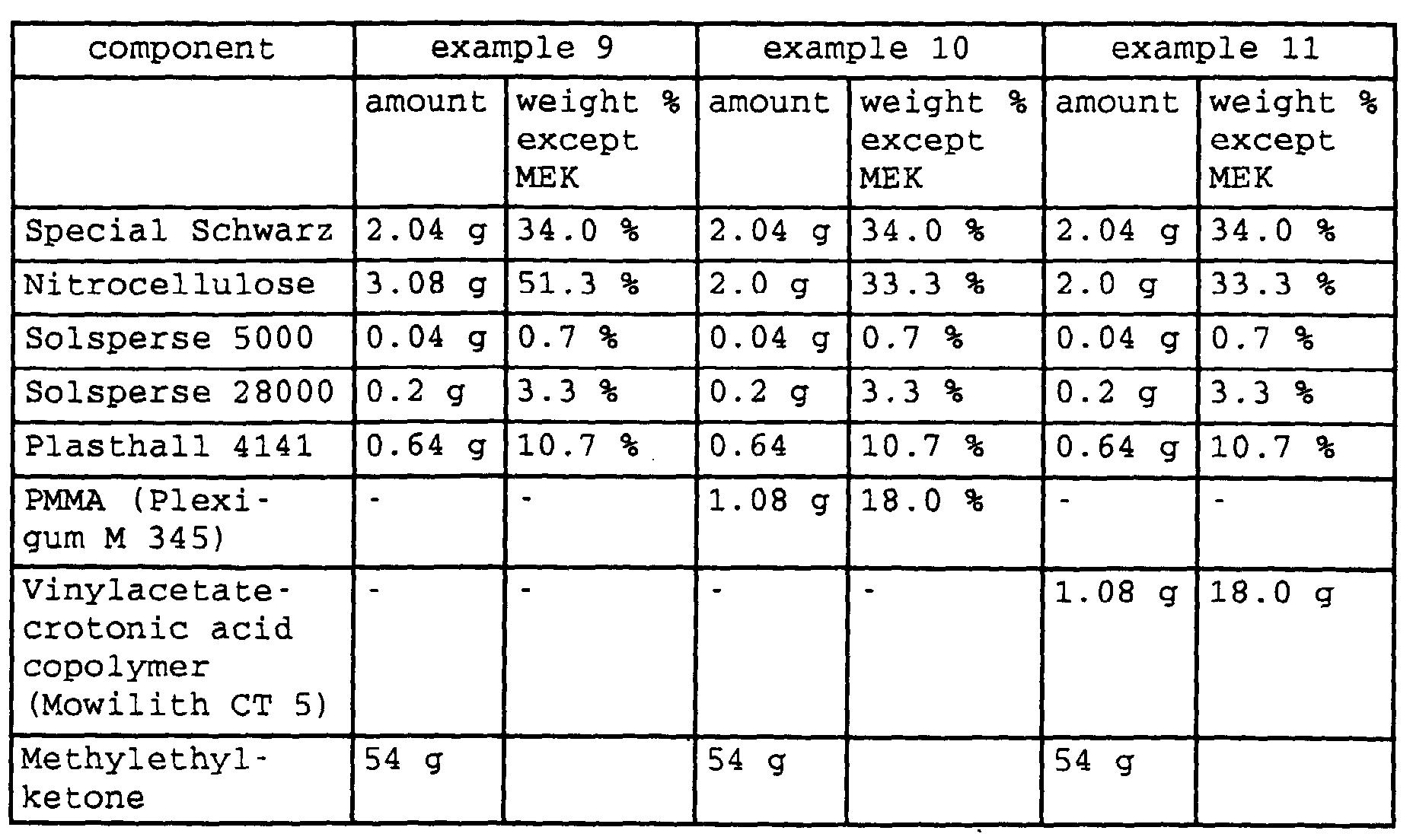
- IR-ablatabe layers were prepared using the procedures as described in example 1 and using the compositions of table 2. In examples 10 and 11 respectively, around 35 % of the nitrocellulose has been substituted by release improving polymers respectively.
- IR-ablatable layers were used for preparing flexographic printing elements according to the procedures described in example 2 and IR-ablated according to example 3.
- Examples 9 - 11 demonstrate that substituting around 35 % of nitrocellulose by release improving polymers does not impart the sensitivity of the IR-ablatable layer to ablation significantly. The release of the protective PET-film on top of the flexographic printing element is significantly improved.
Landscapes
- Physics & Mathematics (AREA)
- Optics & Photonics (AREA)
- Engineering & Computer Science (AREA)
- General Physics & Mathematics (AREA)
- Plasma & Fusion (AREA)
- Manufacturing & Machinery (AREA)
- Photosensitive Polymer And Photoresist Processing (AREA)
- Materials For Photolithography (AREA)
Abstract
Description
- a support,
- a photopolymerizable layer comprising at least one elastomeric binder, at least one polymerizable compound, and at least one photoinitiator or photoinitiator system,
- an IR-ablatable layer which is substantially opaque to actinic radiation, and
- optionally a peelable flexible coversheet,
| component | amount | weight % except MEK | |
| Special Schwarz | 2.3 g | 33.3 % | carbon black pigment |
| Nitrocellulose | 3.6 g | 52.2 % | E 950, Wolff Walsrode (Germany) |
| Solsperse 5000 | 0.05 g | 0.7 % | dispersion agent, Zeneca Ltd. |
| Solsperse 28000 | 0.025 g | 3.6 % | dispersion agent, Zeneca Ltd. |
| Plasthall 4141 | 0.7 g | 10.2 % | Plasticizer comprising triethylene glycol dihexanoate and triethylene glycol dioctanoate (C.P. Hall, Chicago IL) |
| Methylethylketone | 93,1 g | - |


Claims (9)
- Photosensitive printing element used for preparing flexographic printing plates via computer-to-plate technology comprisingwherein the IR-ablatable layer comprises at least one heat-combustible polymeric binder, at least one IR-absorbing material and at least one aliphatic diester of the general formula R1(CO) [O-CHR3-CH2]nO(CO)R2 where n = 1 - 30, R1 and R2 are straight-chain or branched alkyl chains with 1 - 20 carbon atoms, and R3 is H or methyl.a support,a photopolymerizable layer comprising at least one elastomeric binder, at least one polymerizable compound, and at least one photoinitiator or photoinitiator system,an IR-ablatable layer which is substantially opaque to actinic radiation, andoptionally a peelable flexible coversheet,
- Photosensitive printing element according to claim 1 wherein the heat-combustible polymeric binder comprises nitro or nitrate-ester-groups.
- Photosensitive printing element according to claim 1 wherein the heat-combustible polymeric binder is a nitrate ester of cellulose or a cellulose ether.
- Photosensitive printing element according to any of claims 1 to 3 wherein the IR-aborbing material is carbon black.
- Photosensitive printing element according to any one of claims 1 to 4 wherein the aliphatic diester is at least one selected from the group of triethyleneglycol-hexanoic acid diester, triethylenglycol-2-ethyl-hexanoic acid diester and triethyleneglycol-octanonic acid-diester.
- Photosensitive printing element according to any one of claims 1 to 5 wherein the IR-ablatable layer comprises at least one additional polymeric binder.
- Photosensitive printing element according to claim 6 wherein the additional binder is present in an amount of less than 20 % by weight based on the total of all ingredients of the IR-ablatable layer.
- Process for making a flexographic printing plate using the element of any one of claims 1 - 7 comprising(a) optionally removing the peelable flexible coversheet,(b) imagewise irradiating the IR-ablatable layer with an IR-laser to form a mask,(c) overall exposing the photosensitive element to actinic radiation through the mask,(d) treating the product of step (c) with at least one developer solution to remove the residues of the IR-ablatable layer which were not removed during step (b) and to develop the photopolymerizable layer.
- Process according to claim 8 wherein for step (b) a laser apparatus with a rotary drum is used and for irradiation with the IR-laser the flexographic printing element is mounted on the cylindrical surface of the drum.
Priority Applications (1)
| Application Number | Priority Date | Filing Date | Title |
|---|---|---|---|
| EP20000114256 EP1069475B1 (en) | 1999-07-13 | 2000-07-04 | Flexographic printing element comprising an IR-ablatable layer with high sensitivity |
Applications Claiming Priority (3)
| Application Number | Priority Date | Filing Date | Title |
|---|---|---|---|
| EP99113770 | 1999-07-13 | ||
| EP99113770 | 1999-07-13 | ||
| EP20000114256 EP1069475B1 (en) | 1999-07-13 | 2000-07-04 | Flexographic printing element comprising an IR-ablatable layer with high sensitivity |
Publications (2)
| Publication Number | Publication Date |
|---|---|
| EP1069475A1 true EP1069475A1 (en) | 2001-01-17 |
| EP1069475B1 EP1069475B1 (en) | 2002-09-18 |
Family
ID=26071119
Family Applications (1)
| Application Number | Title | Priority Date | Filing Date |
|---|---|---|---|
| EP20000114256 Expired - Lifetime EP1069475B1 (en) | 1999-07-13 | 2000-07-04 | Flexographic printing element comprising an IR-ablatable layer with high sensitivity |
Country Status (1)
| Country | Link |
|---|---|
| EP (1) | EP1069475B1 (en) |
Cited By (20)
| Publication number | Priority date | Publication date | Assignee | Title |
|---|---|---|---|---|
| WO2002085625A1 (en) * | 2001-04-19 | 2002-10-31 | Innovative Elastics Limited | Flexographic printing formes |
| US6599679B2 (en) * | 2000-12-07 | 2003-07-29 | Basf Drucksysteme Gmbh | Photosensitive flexographic printing element having an IR-ablative layer comprising polyether-polyurethanes |
| DE102007006378A1 (en) | 2007-02-08 | 2008-08-14 | Flint Group Germany Gmbh | Photopolymerizable cylindrical endless seamless flexographic printing elements and hard flexographic printing plates made therefrom |
| DE102008024214A1 (en) | 2008-05-19 | 2009-11-26 | Flint Group Germany Gmbh | Photopolymerizable flexographic printing elements for printing with UV inks |
| EP2275870A1 (en) | 2009-07-14 | 2011-01-19 | Flint Group Germany GmbH | Method of manufacturing cylinder-shaped flexographic plates using digital images |
| US8007984B2 (en) | 2003-11-17 | 2011-08-30 | Xsys Print Solutions Deutschland Gmbh | Method for producing flexographic printing forms by thermal development |
| US8066837B2 (en) | 2004-10-14 | 2011-11-29 | Flint Group Germany Gmbh | Processes and apparatus for producing photopolymerizable, cylindrical, continuous, seamless flexographic printing elements |
| DE102010031527A1 (en) | 2010-07-19 | 2012-01-19 | Flint Group Germany Gmbh | Process for the preparation of flexographic printing plates comprising the irradiation with UV LEDs |
| WO2015007667A1 (en) | 2013-07-15 | 2015-01-22 | Flint Group Germany Gmbh | Process of manufacturing flexographic printing forms |
| WO2016030450A1 (en) | 2014-08-28 | 2016-03-03 | Flint Group Germany Gmbh | Apparatus and method for producing flexographic printing plates |
| EP3035123A1 (en) | 2014-12-17 | 2016-06-22 | Flint Group Germany GmbH | Method for producing flexographic printing forms by multiple exposure using UV LEDs |
| EP3054352A1 (en) | 2015-02-06 | 2016-08-10 | Flint Group Germany GmbH | Automated uv-led exposure of flexographic printing plates |
| WO2016188981A1 (en) | 2015-05-28 | 2016-12-01 | Flint Group Germany Gmbh | Digitally imageable flexo-printing plate with integrated barrier layer |
| US9599902B2 (en) | 2006-06-22 | 2017-03-21 | Flint Group Germany Gmbh | Photopolymerisable layered composite for producing flexo printing elements |
| US9671696B2 (en) | 2013-06-14 | 2017-06-06 | Flint Group Germany Gmbh | Flexographic printing element which can be digitally imaged and has a polar, ultra-thin barrier layer |
| US9789679B2 (en) | 2013-09-18 | 2017-10-17 | Flint Group Germany Gmbh | Digitally exposable flexographic printing element and method for producing flexographic printing plates |
| US9937703B2 (en) | 2013-09-30 | 2018-04-10 | Flint Group Germany Gmbh | Device and method for the in-line production of flexographic printing plates |
| WO2018096144A1 (en) | 2016-11-28 | 2018-05-31 | Flint Group Germany Gmbh | Light exposure device and method for exposing plate-shaped materials to light |
| WO2018177500A1 (en) | 2017-03-27 | 2018-10-04 | Flint Group Germany Gmbh | Method for producing pictorial relief structures |
| US10953648B2 (en) | 2013-06-14 | 2021-03-23 | Flint Group Germany Gmbh | Method for producing cylindrical flexo printing elements |
Citations (4)
| Publication number | Priority date | Publication date | Assignee | Title |
|---|---|---|---|---|
| EP0741330A1 (en) * | 1995-05-01 | 1996-11-06 | E.I. Du Pont De Nemours And Company | Flexographic element having an infrared ablatable layer and process for making a flexographic printing plate |
| DE19536805A1 (en) * | 1995-10-02 | 1997-04-03 | Basf Lacke & Farben | Multi-layer recording element suitable for the production of flexographic printing plates by digital information transmission |
| EP0803770A1 (en) * | 1996-04-23 | 1997-10-29 | Agfa-Gevaert N.V. | An imaging element and a method for producing a lithographic plate therewith |
| US5719009A (en) * | 1992-08-07 | 1998-02-17 | E. I. Du Pont De Nemours And Company | Laser ablatable photosensitive elements utilized to make flexographic printing plates |
-
2000
- 2000-07-04 EP EP20000114256 patent/EP1069475B1/en not_active Expired - Lifetime
Patent Citations (4)
| Publication number | Priority date | Publication date | Assignee | Title |
|---|---|---|---|---|
| US5719009A (en) * | 1992-08-07 | 1998-02-17 | E. I. Du Pont De Nemours And Company | Laser ablatable photosensitive elements utilized to make flexographic printing plates |
| EP0741330A1 (en) * | 1995-05-01 | 1996-11-06 | E.I. Du Pont De Nemours And Company | Flexographic element having an infrared ablatable layer and process for making a flexographic printing plate |
| DE19536805A1 (en) * | 1995-10-02 | 1997-04-03 | Basf Lacke & Farben | Multi-layer recording element suitable for the production of flexographic printing plates by digital information transmission |
| EP0803770A1 (en) * | 1996-04-23 | 1997-10-29 | Agfa-Gevaert N.V. | An imaging element and a method for producing a lithographic plate therewith |
Cited By (35)
| Publication number | Priority date | Publication date | Assignee | Title |
|---|---|---|---|---|
| US6599679B2 (en) * | 2000-12-07 | 2003-07-29 | Basf Drucksysteme Gmbh | Photosensitive flexographic printing element having an IR-ablative layer comprising polyether-polyurethanes |
| WO2002085625A1 (en) * | 2001-04-19 | 2002-10-31 | Innovative Elastics Limited | Flexographic printing formes |
| US8007984B2 (en) | 2003-11-17 | 2011-08-30 | Xsys Print Solutions Deutschland Gmbh | Method for producing flexographic printing forms by thermal development |
| US8066837B2 (en) | 2004-10-14 | 2011-11-29 | Flint Group Germany Gmbh | Processes and apparatus for producing photopolymerizable, cylindrical, continuous, seamless flexographic printing elements |
| US9599902B2 (en) | 2006-06-22 | 2017-03-21 | Flint Group Germany Gmbh | Photopolymerisable layered composite for producing flexo printing elements |
| DE102007006378A1 (en) | 2007-02-08 | 2008-08-14 | Flint Group Germany Gmbh | Photopolymerizable cylindrical endless seamless flexographic printing elements and hard flexographic printing plates made therefrom |
| US8288080B2 (en) | 2007-02-08 | 2012-10-16 | Flint Group Germany Gmbh | Photopolymerizable flexographic printing elements and hard flexographic printing formes which are produced therefrom |
| DE102008024214A1 (en) | 2008-05-19 | 2009-11-26 | Flint Group Germany Gmbh | Photopolymerizable flexographic printing elements for printing with UV inks |
| US9939726B2 (en) | 2008-05-19 | 2018-04-10 | Flint Group Germany Gmbh | Photopolymerizable flexographic printing elements for printing with UV inks |
| US8685624B2 (en) | 2008-05-19 | 2014-04-01 | Flint Group Germany Gmbh | Photopolymerizable flexographic printing elements for printing with UV inks |
| EP2275870A1 (en) | 2009-07-14 | 2011-01-19 | Flint Group Germany GmbH | Method of manufacturing cylinder-shaped flexographic plates using digital images |
| WO2012010459A1 (en) | 2010-07-19 | 2012-01-26 | Flint Group Germany Gmbh | Method for producing flexographic printing plates using uv-led irradiation |
| DE102010031527A1 (en) | 2010-07-19 | 2012-01-19 | Flint Group Germany Gmbh | Process for the preparation of flexographic printing plates comprising the irradiation with UV LEDs |
| US10730283B2 (en) | 2010-07-19 | 2020-08-04 | Flint Group Germany Gmbh | Method for producing flexographic printing plates using UV-LED irradiation |
| US10112381B2 (en) | 2010-07-19 | 2018-10-30 | Jens Schadebrodt | Method for producing flexographic printing plates using UV-LED irradiation |
| US10953648B2 (en) | 2013-06-14 | 2021-03-23 | Flint Group Germany Gmbh | Method for producing cylindrical flexo printing elements |
| US9671696B2 (en) | 2013-06-14 | 2017-06-06 | Flint Group Germany Gmbh | Flexographic printing element which can be digitally imaged and has a polar, ultra-thin barrier layer |
| WO2015007667A1 (en) | 2013-07-15 | 2015-01-22 | Flint Group Germany Gmbh | Process of manufacturing flexographic printing forms |
| US9671695B2 (en) | 2013-07-15 | 2017-06-06 | Flint Group Germany Gmbh | Process of manufacturing flexographic printing forms |
| US9789679B2 (en) | 2013-09-18 | 2017-10-17 | Flint Group Germany Gmbh | Digitally exposable flexographic printing element and method for producing flexographic printing plates |
| US9937703B2 (en) | 2013-09-30 | 2018-04-10 | Flint Group Germany Gmbh | Device and method for the in-line production of flexographic printing plates |
| WO2016030450A1 (en) | 2014-08-28 | 2016-03-03 | Flint Group Germany Gmbh | Apparatus and method for producing flexographic printing plates |
| US10691021B2 (en) | 2014-08-28 | 2020-06-23 | Flint Group Germany Gmbh | Apparatus and method for producing flexographic printing plates |
| EP3035123A1 (en) | 2014-12-17 | 2016-06-22 | Flint Group Germany GmbH | Method for producing flexographic printing forms by multiple exposure using UV LEDs |
| US10175580B2 (en) | 2014-12-17 | 2019-01-08 | Flint Group Germany Gmbh | Method for producing a flexographic printing frame through multiple exposures using UV LEDS |
| US10632733B2 (en) | 2015-02-06 | 2020-04-28 | Flint Group Germany Gmbh | Automated UV-LED exposure of flexographic printing plates |
| EP3054352A1 (en) | 2015-02-06 | 2016-08-10 | Flint Group Germany GmbH | Automated uv-led exposure of flexographic printing plates |
| US9889640B2 (en) | 2015-02-06 | 2018-02-13 | Flint Group Germany Gmbh | Automated UV-LED exposure of flexographic printing plates |
| EP3633454A1 (en) | 2015-05-28 | 2020-04-08 | Flint Group Germany GmbH | Method for producing a flexographic printing mould from a digitally imageable photopolymerizable flexographic element with integral barrier layer |
| WO2016188981A1 (en) | 2015-05-28 | 2016-12-01 | Flint Group Germany Gmbh | Digitally imageable flexo-printing plate with integrated barrier layer |
| EP4722812A2 (en) | 2015-05-28 | 2026-04-08 | XSYS Germany GmbH | Method for producing a flexographic printing form from a digitally imageable photopolymerizable flexographic printing element having an integral barrier layer |
| WO2018096144A1 (en) | 2016-11-28 | 2018-05-31 | Flint Group Germany Gmbh | Light exposure device and method for exposing plate-shaped materials to light |
| US11007767B2 (en) | 2016-11-28 | 2021-05-18 | Flint Group Germany Gmbh | Light exposure device and method for exposing plate-shaped materials to light |
| WO2018177500A1 (en) | 2017-03-27 | 2018-10-04 | Flint Group Germany Gmbh | Method for producing pictorial relief structures |
| US11325368B2 (en) | 2017-03-27 | 2022-05-10 | Flint Group Germany Gmbh | Method for producing pictorial relief structures |
Also Published As
| Publication number | Publication date |
|---|---|
| EP1069475B1 (en) | 2002-09-18 |
Similar Documents
| Publication | Publication Date | Title |
|---|---|---|
| US6521390B1 (en) | Flexographic printing element comprising an IR-ablatable layer with improved sensitivity | |
| EP1069475B1 (en) | Flexographic printing element comprising an IR-ablatable layer with high sensitivity | |
| US6037102A (en) | Multilayer recording element suitable for the production of flexographic printing plates by digital information transfer | |
| JP3429634B2 (en) | Method for producing letterpress printing plate using photosensitive polymer and letterpress printing plate obtained thereby | |
| JP3423300B2 (en) | Photosensitive flexographic printing element having at least two IR ablation layers | |
| DE60205005T2 (en) | Photosensitive resin laminate | |
| JP5691274B2 (en) | Photosensitive resin printing plate precursor | |
| US6190832B1 (en) | Preparation of photopolymeric gravure printing plates | |
| JPH07506201A (en) | Photosensitive printing elements used to prepare flexographic printing plates and methods for making flexographic printing plates | |
| JP2009300588A (en) | Photosensitive flexographic printing original plate | |
| JP3511022B2 (en) | Photosensitive flexographic printing element having an IR ablation layer containing polyether-polyurethane | |
| CN110520797A (en) | The mixture of radiation-curable containing low functionalized partly-hydrolysed polyvinyl acetate | |
| JP2025186224A (en) | Flexographic printing plate precursors, imaging assemblies and uses | |
| AU2003275582A1 (en) | Photosensitive resin printing plate original, process for producing the same and process for producing resin relief printing plate therewith | |
| JPH06186743A (en) | Use of alkali-soluble photopolymer in colorproofing structure | |
| US7998659B2 (en) | Photosensitive laminated original printing plate for letterpress printing and process for producing letterpress printing plate using the photosensitive laminated original printing plate | |
| JP2007114255A (en) | Photosensitive resin printing plate precursor and method for producing the same | |
| CN1472597A (en) | Laminating body for IR burning | |
| JP2000128994A (en) | Method for producing crosslinkable water-soluble or water-dispersible composition, composition obtained by the method, and radiation-sensitive mixture | |
| JP2001022059A (en) | Pattern forming composition, image recording material using same and production of recording material | |
| JP2003035954A (en) | Photosensitive printing original plate | |
| JP3781188B2 (en) | Photosensitive resin laminate | |
| JP2003035955A (en) | Photosensitive printing original plate | |
| JP4051604B2 (en) | Photosensitive printing master | |
| JP2004358960A (en) | Plate for lithographic printing |
Legal Events
| Date | Code | Title | Description |
|---|---|---|---|
| PUAI | Public reference made under article 153(3) epc to a published international application that has entered the european phase |
Free format text: ORIGINAL CODE: 0009012 |
|
| AK | Designated contracting states |
Kind code of ref document: A1 Designated state(s): BE DE FR GB IT |
|
| AX | Request for extension of the european patent |
Free format text: AL;LT;LV;MK;RO;SI |
|
| 17P | Request for examination filed |
Effective date: 20010111 |
|
| AKX | Designation fees paid |
Free format text: BE DE FR GB IT |
|
| GRAG | Despatch of communication of intention to grant |
Free format text: ORIGINAL CODE: EPIDOS AGRA |
|
| RAP1 | Party data changed (applicant data changed or rights of an application transferred) |
Owner name: BASF DRUCKSYSTEME GMBH Owner name: AGFA-GEVAERT |
|
| 17Q | First examination report despatched |
Effective date: 20020131 |
|
| GRAG | Despatch of communication of intention to grant |
Free format text: ORIGINAL CODE: EPIDOS AGRA |
|
| GRAG | Despatch of communication of intention to grant |
Free format text: ORIGINAL CODE: EPIDOS AGRA |
|
| GRAH | Despatch of communication of intention to grant a patent |
Free format text: ORIGINAL CODE: EPIDOS IGRA |
|
| GRAH | Despatch of communication of intention to grant a patent |
Free format text: ORIGINAL CODE: EPIDOS IGRA |
|
| GRAA | (expected) grant |
Free format text: ORIGINAL CODE: 0009210 |
|
| AK | Designated contracting states |
Kind code of ref document: B1 Designated state(s): BE DE FR GB IT |
|
| REG | Reference to a national code |
Ref country code: GB Ref legal event code: FG4D |
|
| REF | Corresponds to: |
Ref document number: 60000470 Country of ref document: DE Date of ref document: 20021024 |
|
| ET | Fr: translation filed | ||
| PLBE | No opposition filed within time limit |
Free format text: ORIGINAL CODE: 0009261 |
|
| STAA | Information on the status of an ep patent application or granted ep patent |
Free format text: STATUS: NO OPPOSITION FILED WITHIN TIME LIMIT |
|
| 26N | No opposition filed |
Effective date: 20030619 |
|
| PGFP | Annual fee paid to national office [announced via postgrant information from national office to epo] |
Ref country code: BE Payment date: 20040910 Year of fee payment: 5 |
|
| PG25 | Lapsed in a contracting state [announced via postgrant information from national office to epo] |
Ref country code: IT Free format text: LAPSE BECAUSE OF NON-PAYMENT OF DUE FEES Effective date: 20050704 |
|
| PG25 | Lapsed in a contracting state [announced via postgrant information from national office to epo] |
Ref country code: BE Free format text: LAPSE BECAUSE OF NON-PAYMENT OF DUE FEES Effective date: 20050731 |
|
| PGFP | Annual fee paid to national office [announced via postgrant information from national office to epo] |
Ref country code: FR Payment date: 20050922 Year of fee payment: 6 |
|
| PGFP | Annual fee paid to national office [announced via postgrant information from national office to epo] |
Ref country code: DE Payment date: 20050926 Year of fee payment: 6 Ref country code: GB Payment date: 20050926 Year of fee payment: 6 |
|
| PG25 | Lapsed in a contracting state [announced via postgrant information from national office to epo] |
Ref country code: FR Free format text: LAPSE BECAUSE OF NON-PAYMENT OF DUE FEES Effective date: 20060331 |
|
| REG | Reference to a national code |
Ref country code: FR Ref legal event code: ST Effective date: 20060331 |
|
| PG25 | Lapsed in a contracting state [announced via postgrant information from national office to epo] |
Ref country code: GB Free format text: LAPSE BECAUSE OF NON-PAYMENT OF DUE FEES Effective date: 20060704 |
|
| REG | Reference to a national code |
Ref country code: FR Ref legal event code: TP |
|
| PG25 | Lapsed in a contracting state [announced via postgrant information from national office to epo] |
Ref country code: DE Free format text: LAPSE BECAUSE OF NON-PAYMENT OF DUE FEES Effective date: 20070201 |
|
| GBPC | Gb: european patent ceased through non-payment of renewal fee |
Effective date: 20060704 |
|
| BERE | Be: lapsed |
Owner name: *BASF DRUCKSYSTEME G.M.B.H. Effective date: 20050731 Owner name: *AGFA-GEVAERT Effective date: 20050731 |