EP1069032B1 - Chain for forming tracks - Google Patents
Chain for forming tracks Download PDFInfo
- Publication number
- EP1069032B1 EP1069032B1 EP00114125A EP00114125A EP1069032B1 EP 1069032 B1 EP1069032 B1 EP 1069032B1 EP 00114125 A EP00114125 A EP 00114125A EP 00114125 A EP00114125 A EP 00114125A EP 1069032 B1 EP1069032 B1 EP 1069032B1
- Authority
- EP
- European Patent Office
- Prior art keywords
- collars
- sleeve
- chain
- pivot
- supported
- Prior art date
- Legal status (The legal status is an assumption and is not a legal conclusion. Google has not performed a legal analysis and makes no representation as to the accuracy of the status listed.)
- Expired - Lifetime
Links
- 238000007789 sealing Methods 0.000 claims description 5
- 239000000314 lubricant Substances 0.000 claims description 4
- 125000006850 spacer group Chemical group 0.000 claims description 2
- 238000005461 lubrication Methods 0.000 description 3
- 239000004519 grease Substances 0.000 description 2
- 230000000670 limiting effect Effects 0.000 description 2
- 230000000717 retained effect Effects 0.000 description 2
- 238000005299 abrasion Methods 0.000 description 1
- 230000000295 complement effect Effects 0.000 description 1
- 239000000428 dust Substances 0.000 description 1
- 230000007613 environmental effect Effects 0.000 description 1
- 239000012530 fluid Substances 0.000 description 1
- 230000004048 modification Effects 0.000 description 1
- 238000012986 modification Methods 0.000 description 1
- 230000035515 penetration Effects 0.000 description 1
- 239000004576 sand Substances 0.000 description 1
- 239000002689 soil Substances 0.000 description 1
Images

Classifications
-
- B—PERFORMING OPERATIONS; TRANSPORTING
- B62—LAND VEHICLES FOR TRAVELLING OTHERWISE THAN ON RAILS
- B62D—MOTOR VEHICLES; TRAILERS
- B62D55/00—Endless track vehicles
- B62D55/08—Endless track units; Parts thereof
- B62D55/18—Tracks
- B62D55/20—Tracks of articulated type, e.g. chains
- B62D55/205—Connections between track links
- B62D55/21—Links connected by transverse pivot pins
-
- F—MECHANICAL ENGINEERING; LIGHTING; HEATING; WEAPONS; BLASTING
- F16—ENGINEERING ELEMENTS AND UNITS; GENERAL MEASURES FOR PRODUCING AND MAINTAINING EFFECTIVE FUNCTIONING OF MACHINES OR INSTALLATIONS; THERMAL INSULATION IN GENERAL
- F16H—GEARING
- F16H7/00—Gearings for conveying rotary motion by endless flexible members
- F16H7/06—Gearings for conveying rotary motion by endless flexible members with chains
-
- B—PERFORMING OPERATIONS; TRANSPORTING
- B62—LAND VEHICLES FOR TRAVELLING OTHERWISE THAN ON RAILS
- B62D—MOTOR VEHICLES; TRAILERS
- B62D55/00—Endless track vehicles
- B62D55/08—Endless track units; Parts thereof
- B62D55/18—Tracks
- B62D55/20—Tracks of articulated type, e.g. chains
- B62D55/205—Connections between track links
- B62D55/215—Resilient connections between links
Definitions
- the present invention relates to a chain for forming tracks, particularly for earth-moving vehicles.
- tracks for earth-moving vehicles comprise an articulated chain to which plates or shoes for grip are fixed.
- An articulated chain for forming tracks as defined in the pre-characterizing part of claim 1 is known from WO-A- 98 25 809.
- the aim of the present invention is to provide a chain whose articulation of the links is designed so as to reduce friction forces and therefore reduce the external abrasion of the bushings and of the sprocket wheels meshing with the links.
- 1 generally designates a chain according to the invention.
- the chain is composed of a plurality of links 2 articulated about axes perpendicular to the longitudinal central plane P of the chain.
- Each link 2 is composed of a pair of plates 3 and 4 which are mirror-symmetrical with respect to the plane P.
- Ends 5,6 respectively of plates 3 and 4 are spaced with respect to the plane P and ends 7 and 8 respectively of plates 3,4 are closer than the spaced ends 5 and 6.
- the ends 5-8 are constituted by collars: the ones that form the spaced ends 5 and 6 are thicker than the ones that form the closer ends 7 and 8.
- the collars are designated by the same reference numerals as the ends 5-8.
- the collars 5 and 6, which correspond to the spaced ends, are termed outer collars and form respective circular seats 9 and 10, while the collars 7 and 8, which correspond to the closer ends, are termed inner collars and form circular seats 11 and 12.
- a pivot 13 The opposite ends of a pivot 13 are inserted in the seats 9 and 10, and the pivot is crossed axially by a dead hole 14 which is closed on one side by means of a plug 15 and is connected to the outside by means of a radial hole 16 which lies proximate to the central plane P.
- the dead hole 14 constitutes a vessel for containing a lubricant (oil or grease) which can flow out through the radial hole 16 in order to lubricate the parts that are in sliding contact with the pivot 13, as explained hereinafter.
- a lubricant oil or grease
- the pivot 13 is retained in the seats 9 and 10 by interference forcing or by providing, at the seats 9 and 10, annular slots on the pivot 13 which are engaged by protrusions of the collars formed by deformation.
- the seats 9 and 10 have, on the faces adjacent to the inner collars 7 and 8, respective annular wider portions which form slots 17 and 18 together with the pivot 13.
- the slots 17 and 18 accommodate sealing rings 19 and 20 which are in front contact on the opposite ends of a sleeve 21 superimposed on the pivot 13.
- the sleeve 21 is centered between the collars 5 and 6 by means of spacers 22 and 23 inserted in the slots 17 and 18.
- the length and outside diameter of the sleeve 21 are such that its opposite ends substantially close the slots 17 and 18 without making contact with the outer collars 5 and 6.
- the inner collars 7 and 8 of the plates 3 and 4 that belong to the adjacent link are superimposed on the sleeve 21, adjacent to the outer collars 5 and 6 and inside them.
- the inner collars 7 and 8 also are locked by interference fit on the sleeve 21, so that said sleeve can turn only about the pivot 13.
- the bushing 24 has chamfered opposite ends and an outside diameter which is complementary to the diameter of the tooth spaces of the sprocket wheels around which the chain is wound.
- the vessel 14 by being hydraulically closed by the sleeve 21 and by the sealing rings 19 and 20, allows to differentiate the type of lubrication of the sleeve 21 from the type of lubrication of the bushing 24.
- the vessel 14 can in fact contain a more fluid lubricant, for example oil, to lubricate the region between the sleeve 21 and the pivot 13, while grease can be used to lubricate the region between the bushing 24 and the sleeve 21.
- Figure 3 shows an embodiment in which sealing rings 25 and 26 are interposed between the chamfered ends of the bushing 24 and the inner collars 7 and 8.
- the rings 25 and 26, in addition to preventing the escape of the lubricant from the sliding region between the bushing and the sleeve, prevent the penetration of dust or other dirt in said region, reducing wear.
- Another advantage of the invention is also the possibility to provide a chain which can meet the quality requirements entailed by use in tracked vehicles, also by virtue of the reduced number of parts, which is smaller than that of chains according to other conventional embodiments.
Landscapes
- Engineering & Computer Science (AREA)
- Mechanical Engineering (AREA)
- Chemical & Material Sciences (AREA)
- Combustion & Propulsion (AREA)
- Transportation (AREA)
- General Engineering & Computer Science (AREA)
- General Details Of Gearings (AREA)
- Chain Conveyers (AREA)
- Devices For Conveying Motion By Means Of Endless Flexible Members (AREA)
- Supports For Plants (AREA)
- Recording Or Reproducing By Magnetic Means (AREA)
- Accessory Devices And Overall Control Thereof (AREA)
- Magnetic Heads (AREA)
- Lubrication Of Internal Combustion Engines (AREA)
- Polishing Bodies And Polishing Tools (AREA)
- Transmission Devices (AREA)
- Automatic Tool Replacement In Machine Tools (AREA)
- Sawing (AREA)
- Electric Cable Arrangement Between Relatively Moving Parts (AREA)
Abstract
Description
- The present invention relates to a chain for forming tracks, particularly for earth-moving vehicles.
- It is known that tracks for earth-moving vehicles comprise an articulated chain to which plates or shoes for grip are fixed.
- An articulated chain for forming tracks as defined in the pre-characterizing part of
claim 1 is known from WO-A- 98 25 809. - Due to the extreme environmental conditions in which tracks have to operate, the moving parts and particularly the pivots and the bushings forming the articulations of the chain, are subjected to intense wear.
- Considerable progress has been made in limiting the wear between the bushings and the pivots by introducing sealed-lubrication chains. However, this progress has not allowed to appreciably reduce external wear of the bushings caused by their friction between the teeth of the sprocket wheels around which the chain is wound. This wear is particularly increased by the fact that the bushings and sprocket wheels tend to soil with sand or other abrasive dirt and by the intense pressures with which the bushings are pushed into the tooth spaces by the traction force applied to the chain by the driving wheels.
- The aim of the present invention is to provide a chain whose articulation of the links is designed so as to reduce friction forces and therefore reduce the external abrasion of the bushings and of the sprocket wheels meshing with the links.
- This aim is achieved with a chain for forming tracks, according to
claim 1. - Further characteristics and advantages of the present invention will become better apparent from the following description of a preferred embodiment, illustrated only by way of non-limitative example in the accompanying drawings, wherein:
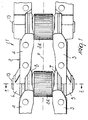
- Figure 1 is a plan view of a link of chain for the track of a tracked vehicle, according to the present invention;
- Figure 2 is a sectional view, taken along the line II-II of Figure 1;
- Figure 3 is a sectional view of another embodiment of the link according to the present invention.
- With reference to the above figures, 1 generally designates a chain according to the invention. The chain is composed of a plurality of links 2 articulated about axes perpendicular to the longitudinal central plane P of the chain.
- Each link 2 is composed of a pair of
plates - Ends 5,6 respectively of
plates ends plates spaced ends - The ends 5-8 are constituted by collars: the ones that form the
spaced ends closer ends collars circular seats collars circular seats 11 and 12. - The opposite ends of a
pivot 13 are inserted in theseats dead hole 14 which is closed on one side by means of aplug 15 and is connected to the outside by means of aradial hole 16 which lies proximate to the central plane P. - The
dead hole 14 constitutes a vessel for containing a lubricant (oil or grease) which can flow out through theradial hole 16 in order to lubricate the parts that are in sliding contact with thepivot 13, as explained hereinafter. Thepivot 13 is retained in theseats seats pivot 13 which are engaged by protrusions of the collars formed by deformation. - The
seats inner collars slots pivot 13. Theslots sealing rings 19 and 20 which are in front contact on the opposite ends of asleeve 21 superimposed on thepivot 13. - The
sleeve 21 is centered between thecollars spacers slots sleeve 21 are such that its opposite ends substantially close theslots outer collars - The
inner collars plates sleeve 21, adjacent to theouter collars inner collars sleeve 21, so that said sleeve can turn only about thepivot 13. - The described articulation is completed by a bushing 24 which is rotatably supported on the
sleeve 20 and is axially retained between theinner collars - The
bushing 24 has chamfered opposite ends and an outside diameter which is complementary to the diameter of the tooth spaces of the sprocket wheels around which the chain is wound. - The operation of the described articulation is evident from the above description. In particular, it should be noted that since the
bushing 24 can rotate on thesleeve 21, it can remain stationary with respect to the sprocket wheels, allowing to reduce sliding friction and therefore reduce wear on said sprocket wheels. - It is particularly important that the
vessel 14, by being hydraulically closed by thesleeve 21 and by thesealing rings 19 and 20, allows to differentiate the type of lubrication of thesleeve 21 from the type of lubrication of thebushing 24. Thevessel 14 can in fact contain a more fluid lubricant, for example oil, to lubricate the region between thesleeve 21 and thepivot 13, while grease can be used to lubricate the region between thebushing 24 and thesleeve 21. - The same inventive concept can of course also be applied to chains of the non-lubricated type, i.e., chains which do not have the
hole 14 and thesealing rings 19 and 20. - The described invention is susceptible of numerous modifications and variations, all of which are within the scope of the appended claims.
- Figure 3 shows an embodiment in which
sealing rings bushing 24 and theinner collars rings - Another advantage of the invention is also the possibility to provide a chain which can meet the quality requirements entailed by use in tracked vehicles, also by virtue of the reduced number of parts, which is smaller than that of chains according to other conventional embodiments.
- Where technical features mentioned in any claim are followed by reference signs, those reference signs have been included for the sole purpose of increasing the intelligibility of the claims and accordingly, such reference signs do not have any limiting effect on the interpretation of each element identified by way of example by such reference signs.
Claims (4)
- A chain for forming tracks, composed of a plurality of links articulated about axes perpendicular to a longitudinal extension of the chain, each link being composed of two plates (3, 4) having two spaced ends and two closer ends, said ends forming collars (5, 6) supported on articulation pivots (13) so that the closer ends of one link form collars (7, 8) which lie internally with respect to the spaced ends of an adjacent link that are supported on the same pivot, the chain further comprising a sleeve (21) supported on said pivot and arranged between said spaced ends, and a bushing (24) which is supported on said sleeve (21) between said closer ends characterized in that:said inner collars (7, 8) are fitted on said sleeve (21); andsaid bushing (24) has chamfered ends opposite said inner collars (7, 8).
- The chain according to claim 1, characterized in that sealing rings (25, 26) are interposed between said inner collars (7, 8) and opposite the chamfered ends of said bushing (24).
- The chain according to claim 1, characterized in that said pivot (13) is crossed by an axial hole (14) which is connected to a region where said sleeve (21) slides on said pivot (13), said hole (14) constituting a vessel for containing a lubricant.
- The chain according to claim 1, characterized in that said spaced and closer ends form respective outer collars (5, 6) and inner collars (7, 8), the outer collars (5, 6), which form said spaced ends, being thicker than the inner collars, which form said closer ends, and having engagement seats (9, 10) for opposite ends of said pivot (13), respective slots (17, 18) being provided on internal faces of said outer collars (5, 6) and around said pivot (13), said slots accommodating rings (19, 20) in front hermetic contact on the opposite ends of said sleeve (21), said sleeve (21) being arranged between said outer collars (5, 6) by means of spacers (22, 23) inserted in said slots (17, 18).
Applications Claiming Priority (2)
| Application Number | Priority Date | Filing Date | Title |
|---|---|---|---|
| ITBO990395 | 1999-07-14 | ||
| IT1999BO000395A IT1309336B1 (en) | 1999-07-14 | 1999-07-14 | CHAIN FOR THE CREATION OF TRACKS. |
Publications (4)
| Publication Number | Publication Date |
|---|---|
| EP1069032A2 EP1069032A2 (en) | 2001-01-17 |
| EP1069032A3 EP1069032A3 (en) | 2002-04-03 |
| EP1069032B1 true EP1069032B1 (en) | 2006-11-29 |
| EP1069032B8 EP1069032B8 (en) | 2007-01-24 |
Family
ID=11344124
Family Applications (1)
| Application Number | Title | Priority Date | Filing Date |
|---|---|---|---|
| EP00114125A Expired - Lifetime EP1069032B8 (en) | 1999-07-14 | 2000-07-11 | Chain for forming tracks |
Country Status (6)
| Country | Link |
|---|---|
| EP (1) | EP1069032B8 (en) |
| KR (1) | KR20010015293A (en) |
| AT (1) | ATE346785T1 (en) |
| BR (1) | BR0002799A (en) |
| DE (1) | DE60032065T2 (en) |
| IT (1) | IT1309336B1 (en) |
Cited By (1)
| Publication number | Priority date | Publication date | Assignee | Title |
|---|---|---|---|---|
| CN108778914A (en) * | 2016-03-14 | 2018-11-09 | 卡特彼勒公司 | Track pin communication system and method |
Families Citing this family (6)
| Publication number | Priority date | Publication date | Assignee | Title |
|---|---|---|---|---|
| EP1591350A3 (en) | 2004-04-27 | 2006-08-09 | Intertractor GmbH | Track for tracklaying vehicles |
| US9505453B2 (en) | 2013-08-29 | 2016-11-29 | Caterpillar Inc. | Track joint assemblies |
| US9604681B2 (en) | 2013-08-29 | 2017-03-28 | Caterpillar Inc. | Track joint assemblies |
| US9623920B2 (en) | 2013-08-29 | 2017-04-18 | Caterpillar Inc. | Track joint assemblies |
| US9434425B2 (en) | 2013-08-29 | 2016-09-06 | Caterpillar Inc. | Track joint assemblies |
| USD1122009S1 (en) * | 2024-08-13 | 2026-04-14 | TP Design LLC | Reception table |
Family Cites Families (2)
| Publication number | Priority date | Publication date | Assignee | Title |
|---|---|---|---|---|
| JP3683060B2 (en) * | 1996-12-13 | 2005-08-17 | 株式会社小松製作所 | Tracked vehicle tracked vehicle |
| DE19752391C1 (en) * | 1997-11-26 | 1999-05-27 | Intertractor Zweigniederlassun | Track for endless track vehicle |
-
1999
- 1999-07-14 IT IT1999BO000395A patent/IT1309336B1/en active
-
2000
- 2000-07-11 DE DE60032065T patent/DE60032065T2/en not_active Expired - Lifetime
- 2000-07-11 EP EP00114125A patent/EP1069032B8/en not_active Expired - Lifetime
- 2000-07-11 AT AT00114125T patent/ATE346785T1/en not_active IP Right Cessation
- 2000-07-12 KR KR1020000039808A patent/KR20010015293A/en not_active Ceased
- 2000-07-14 BR BR0002799-5A patent/BR0002799A/en not_active IP Right Cessation
Cited By (1)
| Publication number | Priority date | Publication date | Assignee | Title |
|---|---|---|---|---|
| CN108778914A (en) * | 2016-03-14 | 2018-11-09 | 卡特彼勒公司 | Track pin communication system and method |
Also Published As
| Publication number | Publication date |
|---|---|
| ITBO990395A1 (en) | 2001-01-14 |
| ITBO990395A0 (en) | 1999-07-14 |
| BR0002799A (en) | 2001-03-13 |
| DE60032065D1 (en) | 2007-01-11 |
| DE60032065T2 (en) | 2007-06-28 |
| IT1309336B1 (en) | 2002-01-22 |
| EP1069032A3 (en) | 2002-04-03 |
| ATE346785T1 (en) | 2006-12-15 |
| KR20010015293A (en) | 2001-02-26 |
| EP1069032B8 (en) | 2007-01-24 |
| EP1069032A2 (en) | 2001-01-17 |
Similar Documents
| Publication | Publication Date | Title |
|---|---|---|
| RU2392164C2 (en) | Cartridge assembly for caterpillar track of caterpillar working device and working device using said cartridge assembly | |
| JP3356777B2 (en) | Endless track chain for track type vehicles | |
| US6206491B1 (en) | Crawler device for crawler vehicle | |
| EP0549109B1 (en) | Method and apparatus for retaining a track chain joint | |
| US5069509A (en) | Endless track chain with rotatable sleeve | |
| KR101650288B1 (en) | Dual-bushing track chain cartridge | |
| US5887958A (en) | Track link assembly having positive pin retention | |
| US6866351B2 (en) | Rotary bushing type crawler track | |
| AU2020211907B2 (en) | Sealing system for a track | |
| CN102421661A (en) | Tracks with swivel bushings for tracked vehicles | |
| JPH08230729A (en) | Truck roller assembly | |
| EP1069032A2 (en) | Chain for forming tracks | |
| KR101160397B1 (en) | Roller chain | |
| US3801163A (en) | Track chain seal | |
| JP2023505793A (en) | A track joint assembly for a ground engaging track with a track pin having an enlarged central section | |
| EP3947121B1 (en) | Coupling for links of tracks | |
| AU2004279689B2 (en) | Pin assembly of track roller bogie in crawler type traveling apparatus and crawler type traveling apparatus with the assembly | |
| JP4541532B2 (en) | Seal chain | |
| CN111806584B (en) | A locking unit, track and walking device | |
| GB2390411A (en) | A roller chain | |
| WO2025034356A9 (en) | Track link assembly, track system and construction machine | |
| SU766947A1 (en) | Elastic track for vehicle | |
| EP0016279A1 (en) | Link chain | |
| JP2002302075A (en) | Crawler belt device for crawler vehicle |
Legal Events
| Date | Code | Title | Description |
|---|---|---|---|
| PUAI | Public reference made under article 153(3) epc to a published international application that has entered the european phase |
Free format text: ORIGINAL CODE: 0009012 |
|
| AK | Designated contracting states |
Kind code of ref document: A2 Designated state(s): AT BE CH CY DE DK ES FI FR GB GR IE IT LI LU MC NL PT SE |
|
| AX | Request for extension of the european patent |
Free format text: AL;LT;LV;MK;RO;SI |
|
| PUAL | Search report despatched |
Free format text: ORIGINAL CODE: 0009013 |
|
| AK | Designated contracting states |
Kind code of ref document: A3 Designated state(s): AT BE CH CY DE DK ES FI FR GB GR IE IT LI LU MC NL PT SE |
|
| AX | Request for extension of the european patent |
Free format text: AL;LT;LV;MK;RO;SI |
|
| 17P | Request for examination filed |
Effective date: 20020927 |
|
| AKX | Designation fees paid |
Free format text: AT BE CH CY DE DK ES FI FR GB GR IE IT LI LU MC NL PT SE |
|
| 17Q | First examination report despatched |
Effective date: 20040730 |
|
| GRAP | Despatch of communication of intention to grant a patent |
Free format text: ORIGINAL CODE: EPIDOSNIGR1 |
|
| RAP1 | Party data changed (applicant data changed or rights of an application transferred) |
Owner name: ITALTRACTOR I.T.M. S.P.A. |
|
| GRAS | Grant fee paid |
Free format text: ORIGINAL CODE: EPIDOSNIGR3 |
|
| GRAA | (expected) grant |
Free format text: ORIGINAL CODE: 0009210 |
|
| AK | Designated contracting states |
Kind code of ref document: B1 Designated state(s): AT BE CH CY DE DK ES FI FR GB GR IE IT LI LU MC NL PT SE |
|
| PG25 | Lapsed in a contracting state [announced via postgrant information from national office to epo] |
Ref country code: NL Free format text: LAPSE BECAUSE OF FAILURE TO SUBMIT A TRANSLATION OF THE DESCRIPTION OR TO PAY THE FEE WITHIN THE PRESCRIBED TIME-LIMIT Effective date: 20061129 Ref country code: CH Free format text: LAPSE BECAUSE OF FAILURE TO SUBMIT A TRANSLATION OF THE DESCRIPTION OR TO PAY THE FEE WITHIN THE PRESCRIBED TIME-LIMIT Effective date: 20061129 Ref country code: LI Free format text: LAPSE BECAUSE OF FAILURE TO SUBMIT A TRANSLATION OF THE DESCRIPTION OR TO PAY THE FEE WITHIN THE PRESCRIBED TIME-LIMIT Effective date: 20061129 Ref country code: AT Free format text: LAPSE BECAUSE OF FAILURE TO SUBMIT A TRANSLATION OF THE DESCRIPTION OR TO PAY THE FEE WITHIN THE PRESCRIBED TIME-LIMIT Effective date: 20061129 Ref country code: FI Free format text: LAPSE BECAUSE OF FAILURE TO SUBMIT A TRANSLATION OF THE DESCRIPTION OR TO PAY THE FEE WITHIN THE PRESCRIBED TIME-LIMIT Effective date: 20061129 Ref country code: BE Free format text: LAPSE BECAUSE OF FAILURE TO SUBMIT A TRANSLATION OF THE DESCRIPTION OR TO PAY THE FEE WITHIN THE PRESCRIBED TIME-LIMIT Effective date: 20061129 |
|
| REG | Reference to a national code |
Ref country code: GB Ref legal event code: FG4D |
|
| REG | Reference to a national code |
Ref country code: CH Ref legal event code: EP Ref country code: IE Ref legal event code: FG4D |
|
| REG | Reference to a national code |
Ref country code: IE Ref legal event code: FG4D |
|
| REF | Corresponds to: |
Ref document number: 60032065 Country of ref document: DE Date of ref document: 20070111 Kind code of ref document: P |
|
| PG25 | Lapsed in a contracting state [announced via postgrant information from national office to epo] |
Ref country code: SE Free format text: LAPSE BECAUSE OF FAILURE TO SUBMIT A TRANSLATION OF THE DESCRIPTION OR TO PAY THE FEE WITHIN THE PRESCRIBED TIME-LIMIT Effective date: 20070228 Ref country code: DK Free format text: LAPSE BECAUSE OF FAILURE TO SUBMIT A TRANSLATION OF THE DESCRIPTION OR TO PAY THE FEE WITHIN THE PRESCRIBED TIME-LIMIT Effective date: 20070228 |
|
| PG25 | Lapsed in a contracting state [announced via postgrant information from national office to epo] |
Ref country code: ES Free format text: LAPSE BECAUSE OF FAILURE TO SUBMIT A TRANSLATION OF THE DESCRIPTION OR TO PAY THE FEE WITHIN THE PRESCRIBED TIME-LIMIT Effective date: 20070312 |
|
| PG25 | Lapsed in a contracting state [announced via postgrant information from national office to epo] |
Ref country code: PT Free format text: LAPSE BECAUSE OF FAILURE TO SUBMIT A TRANSLATION OF THE DESCRIPTION OR TO PAY THE FEE WITHIN THE PRESCRIBED TIME-LIMIT Effective date: 20070430 |
|
| NLV1 | Nl: lapsed or annulled due to failure to fulfill the requirements of art. 29p and 29m of the patents act | ||
| EN | Fr: translation not filed | ||
| PLBE | No opposition filed within time limit |
Free format text: ORIGINAL CODE: 0009261 |
|
| STAA | Information on the status of an ep patent application or granted ep patent |
Free format text: STATUS: NO OPPOSITION FILED WITHIN TIME LIMIT |
|
| 26N | No opposition filed |
Effective date: 20070830 |
|
| GBPC | Gb: european patent ceased through non-payment of renewal fee |
Effective date: 20070711 |
|
| PG25 | Lapsed in a contracting state [announced via postgrant information from national office to epo] |
Ref country code: MC Free format text: LAPSE BECAUSE OF NON-PAYMENT OF DUE FEES Effective date: 20070731 Ref country code: FR Free format text: LAPSE BECAUSE OF FAILURE TO SUBMIT A TRANSLATION OF THE DESCRIPTION OR TO PAY THE FEE WITHIN THE PRESCRIBED TIME-LIMIT Effective date: 20070720 Ref country code: GR Free format text: LAPSE BECAUSE OF FAILURE TO SUBMIT A TRANSLATION OF THE DESCRIPTION OR TO PAY THE FEE WITHIN THE PRESCRIBED TIME-LIMIT Effective date: 20070301 |
|
| PG25 | Lapsed in a contracting state [announced via postgrant information from national office to epo] |
Ref country code: GB Free format text: LAPSE BECAUSE OF NON-PAYMENT OF DUE FEES Effective date: 20070711 |
|
| PG25 | Lapsed in a contracting state [announced via postgrant information from national office to epo] |
Ref country code: IE Free format text: LAPSE BECAUSE OF NON-PAYMENT OF DUE FEES Effective date: 20070711 |
|
| PG25 | Lapsed in a contracting state [announced via postgrant information from national office to epo] |
Ref country code: FR Free format text: LAPSE BECAUSE OF FAILURE TO SUBMIT A TRANSLATION OF THE DESCRIPTION OR TO PAY THE FEE WITHIN THE PRESCRIBED TIME-LIMIT Effective date: 20061129 |
|
| PG25 | Lapsed in a contracting state [announced via postgrant information from national office to epo] |
Ref country code: CY Free format text: LAPSE BECAUSE OF FAILURE TO SUBMIT A TRANSLATION OF THE DESCRIPTION OR TO PAY THE FEE WITHIN THE PRESCRIBED TIME-LIMIT Effective date: 20061129 Ref country code: LU Free format text: LAPSE BECAUSE OF NON-PAYMENT OF DUE FEES Effective date: 20070711 |
|
| PGFP | Annual fee paid to national office [announced via postgrant information from national office to epo] |
Ref country code: DE Payment date: 20190628 Year of fee payment: 20 Ref country code: IT Payment date: 20190717 Year of fee payment: 20 |
|
| REG | Reference to a national code |
Ref country code: DE Ref legal event code: R071 Ref document number: 60032065 Country of ref document: DE |