EP1068950A1 - Printing apparatus and printing method therefor - Google Patents
Printing apparatus and printing method therefor Download PDFInfo
- Publication number
- EP1068950A1 EP1068950A1 EP00114169A EP00114169A EP1068950A1 EP 1068950 A1 EP1068950 A1 EP 1068950A1 EP 00114169 A EP00114169 A EP 00114169A EP 00114169 A EP00114169 A EP 00114169A EP 1068950 A1 EP1068950 A1 EP 1068950A1
- Authority
- EP
- European Patent Office
- Prior art keywords
- negative electrodes
- fluid
- ink
- positive electrode
- rotation
- Prior art date
- Legal status (The legal status is an assumption and is not a legal conclusion. Google has not performed a legal analysis and makes no representation as to the accuracy of the status listed.)
- Granted
Links
Images



Classifications
-
- B—PERFORMING OPERATIONS; TRANSPORTING
- B41—PRINTING; LINING MACHINES; TYPEWRITERS; STAMPS
- B41C—PROCESSES FOR THE MANUFACTURE OR REPRODUCTION OF PRINTING SURFACES
- B41C1/00—Forme preparation
- B41C1/10—Forme preparation for lithographic printing; Master sheets for transferring a lithographic image to the forme
- B41C1/105—Forme preparation for lithographic printing; Master sheets for transferring a lithographic image to the forme by electrocoagulation, by electro-adhesion or by electro-releasing of material, e.g. a liquid from a gel
Definitions
- the present invention relates to a printing apparatus, and more particularly to a printing apparatus for forming a desired image by coagulating a portion of liquid ink by electrical energizing, and transferring this to a printing object such as paper, to thereby affect printing, and to a printing method therefor.
- This type of printing apparatuses is applicable to many kinds of low volume printing, and is disclosed for example in Published Japanese translation No. Hei 4-504688 of PCT (WO 09011897).
- This apparatus comprises: a rotation drum with a circumferential surface functioning as a positive electrode; a plurality of negative electrodes arranged at a predetermined spacing in an axial direction of the rotation drum and facing the circumferential surface of the rotation drum with a predetermined space; an injector for injecting and replenishing liquid ink from a rotation input side to the space between the negative electrodes and the circumferential surface of the rotation drum; a coating unit arranged on the rotation input side of the injector for coating an olefinic substance containing a metallic oxide onto the circumferential surface of the rotation drum; an energizer for energizing selected negative electrodes of the plurality of negative electrodes in a condition with ink disposed between the negative electrodes and the positive electrode, to thereby coagulate and adhere part of the ink onto the circumferential surface of the rotation drum to
- the present invention is aimed at dealing with the abovementioned problems, with the object of suppressing the adherence of coagulated ink to the negative terminal surface and the surroundings thereof.
- the invention is characterized in that in the abovementioned printing apparatus, on the rotation input side of the plurality of negative electrodes there is provided a discharge port whereby a fluid can be discharged towards the negative electrode surface and the surroundings thereof, and there is provided a fluid supply device for supplying a fluid (which may be a liquid or a gas) to the discharge port.
- a fluid is supplied from the fluid supply device to the discharge port, and the fluid flows from the discharge port to the negative electrode surface and the surroundings thereof. Therefore, the adhering of ink which has been coagulated by energizing, to the negative electrode surface and the surroundings thereof can be suppressed, or the coagulated ink adhered to the negative electrode surface and the surroundings thereof can be washed off.
- the operation frequency for removing coagulated ink from the surface of the negative electrode and the surroundings thereof, with a removal device such as a rotating brush can be reduced (or eliminated). Therefore the number of printing interruptions can be reduced (or eliminated) and printing efficiency thus increased.
- a solution layer of electrolyte can be continuously formed on the negative electrode side in the space between the electrodes.
- a solution layer of ink can be continuously formed on the positive electrode side. Consequently, as well as preventing the adherence of ink to the negative electrode surface and the surroundings thereof by means of the solution layer of electrolyte, energizing between electrodes can be performed through the solution layer of electrolyte and the solution layer of ink. Hence extended continuous printing or repetitive printing becomes possible, enabling an improvement in printing efficiency.
- the fluid supplied to the discharge port is a washing fluid (for example tap water, or a washing liquid containing a solvent, a surface active agent, or the like)
- the fluid supply device is configured for momentarily supply the washing fluid at high pressure
- this same ink can be removed by momentarily supplying the washing fluid at high pressure at a timing such as a pause in the printing during printing.
- the negative electrode surface and the surroundings thereof can also be cooled by the fluid supplied from the discharge port. Hence the coagulation of ink by energizing can be suppressed at the negative electrode surface and the surroundings thereof.
- FIG. 1 schematically shows an electrocoagulation printing apparatus according to the present invention.
- This printing apparatus has a known construction such as disclosed in Published Japanese translation No. Hei 4-504688, comprising a rotation drum 10, negative electrodes 20, an injector 30, a coating unit 40, an energizer 50, a removal device 60, a transfer device 70, and a washing device 80.
- this comprises a novel construction in the form of discharge ports 90 and a fluid supply device 100.
- the cylindrical surface functions as a positive electrode 11, and is rotatably supported in a frame (omitted from the figure) so as to be rotatably driven in a counterclockwise direction as shown in the figure by a drive unit (omitted from the figure).
- the negative electrodes 20, as shown partially enlarged in FIG. 2 and FIG. 3, are metal electrodes of square section (with one side approximately 30 ⁇ m) embedded in an insulating resin 21, and are multiply arranged in a line at a predetermined spacing D (approximately 60 ⁇ m) in the axial direction of the rotation drum 10. Moreover, these are attached to the frame so as to face the circumferential surface of the rotation drum 10 with a predetermined space S (approximately 30 ⁇ 100 ⁇ m).
- the injector 30 injects and replenishes liquid ink A from the rotation input side to the space between the plurality of negative electrodes 20 and the circumferential surface of the rotation drum 10, and is attached to the frame.
- the coating unit 40 is arranged on the rotation input side of the injector 30, and attached to the frame, for continuously coating an olefinic substance containing a metallic oxide onto the circumferential surface of the rotation drum 10.
- the energizer 50 is for energizing selected negative electrodes of the plurality of negative electrodes 20 in a condition with ink A disposed between the negative electrodes 20 and the positive electrode 11 of the rotation drum 10, to thereby coagulate and adhere a part A1 (refer to FIG. 2) of the ink onto the circumferential surface of the rotation drum 10 to form a desired image.
- Energizing signals are sent to the energizer 50 from a control unit (not shown in the figure) via a cable 51.
- the removal device 60 is arranged on the rotation output side of the space 6 between the electrodes, and has a flexible rubber spatula 61 for removing residual non-coagulated ink from the circumferential surface of the rotation drum 10. The removed ink is then recycled.
- the transfer device 70 is arranged on the rotation output side of the removal device 60 for transferring a desired image which has been coagulated and adhered to the circumferential surface of the rotation drum 10, onto an object to be printed B such as paper, and incorporates a press roller 71 which rotates in the clockwise direction in the figure.
- the washing device 80 is arranged on the rotation output side of the transfer device 70 for continuously washing the circumferential surface of the rotation drum 10.
- the discharge ports 90 as shown in FIG. 3, are formed in a circular shape (approximately 30 ⁇ m diameter) and are respectively provided in an insulating resin 21 so as to correspond to the respective negative electrodes 20, and on the rotation input side (ink inflow side) thereof.
- the discharge ports 90 are located at a position separated by a predetermined distance L (which can be appropriately set) from the respective negative electrodes 20, so that an electrolyte C can flow towards the surface of the respective electrodes 20 and the surroundings thereof.
- aqueous solutions of salts such as potassium chloride.
- the fluid supply device 100 continuously supplies at a predetermined pressure (low pressure), the electrolyte C to the respective discharge ports 90 when liquid ink A is injected from the injection device 30 towards the space S between the electrodes.
- the fluid supply device 100 comprises; a supply pipe 102 with a supply pump 101 disposed therein, a communicating path 103 provided in the insulating resin 21 with one end connected to the supply pipe 102, a plurality of branch paths 104 provided in the insulating resin-21 each with one end connected to the communicating path 103 and the other end connected to the respective discharge ports 90, a return pipe 105 connected to the other end of the communicating path 103 for returning the surplus electrolyte C to a tank 107, and a control valve 106 disposed in the return pipe 105 for controlling the flow quantity of electrolyte C supplied to the respective discharge ports 90 through the respective branch paths 104.
- desired printing onto the object to be printed B is performed by realizing: a coating process for coating an olefinic substance containing a metallic oxide onto the circumferential surface of the rotation drum 10 with the coating unit 40; an ink replenishing process for injecting and replenishing liquid ink A into the space S between electrodes, by the injector 30; a coagulation process and a process for supplying electrolyte C, for forming a desired image by energizing at a facing portion of the circumferential surface of the rotation drum 10 and the negative electrodes 20 and the rotation input side thereof; a removal process for removing residual non-coagulated ink from the circumferential surface of the rotation drum 10 by means of the removal device 60; a transfer process for transferring a desired image from the circumferential surface of the rotation drum 10 onto the object to be printed B by means of the transfer device 70; and a washing process for washing the circumferential surface of the rotation drum 10 by means of the washing device 80.
- a coagulation process and a process for supplying electrolyte C, for forming a desired image by energizing at a facing portion of the circumferential surface of the rotation drum 10 and the negative electrodes 20 and the rotation input side thereof Furthermore, a solution layer of electrolyte C can be continuously formed on the negative electrodes 20 side in the space S between the electrodes as shown in FIG. 2. Moreover a solution layer of ink A can be continuously formed on the positive electrode 11 side.
- the fluid supply device 100 incorporates a function for cooling the electrolyte C which is collectively supplied to the discharge ports 90. Therefore the surface of the negative electrodes 20 and the surroundings thereof can be cooled by the electrolyte C supplied from the discharge ports 90. Hence coagulation of the ink A at the surface of the negative electrodes 20 and the surroundings thereof due to energizing can be suppressed.
- the abovementioned embodiment is effected by adopting the fluid supply device 100 which continuously supplies at a low pressure, the electrolyte C to the respective discharge ports 90 when the liquid ink A is injected from the injection device 30 towards the space S between the electrodes.
- the timing for supplying the fluid to the respective discharge ports can be suitably set, and for example the fluid supply device rather than being limited to the abovementioned embodiment, can momentarily supply a washing fluid (for example tap water, or a washing liquid containing a solvent, a surface active agent, or the like, or a suitable gas) at high pressure, then the invention can be effected by supplying the washing fluid at high pressure at a timing such as a pause in the printing during printing.
- this is effected by providing the discharge ports 90, and the communicating path 103 and the branch paths 104 of the fluid supply device 100 in the insulating resin 21 which retains the negative electrodes 20.
- this may also be effected by providing parts corresponding to the discharge ports 90 and the communicating path 103 and the branch paths 104 of the fluid supply device 100 in a different member to the insulating resin 21 which retains the negative electrodes 20.
- the discharge ports 90 are formed in a circular shape and are provided separated by a predetermined distance L from the negative electrodes 20 on the upstream side.
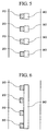
- the shape of the discharge ports and the arrangement positions may be appropriately set. For example as shown in FIG. 5, this may be effected by forming the discharge ports 90 in a square shape and providing these respectively adjacent to the respective negative electrodes 20.
- this may be effected by forming the discharge ports 90 in a strip form and providing this adjacent to the respective negative electrodes 20.
- this may be effected by forming the discharge ports 90 in a U-shape and providing these surrounding the respective negative electrodes 20 from the upstream side.
- the electrolyte C is circulated in the fluid supply device 100 and naturally cooled.
- the invention may also be effected by providing a separate forced cooling device and forcefully cooling the electrolyte C by means of this forced cooling device.
- the invention may also be effected by adopting a fluid supply device which does not incorporate a cooling function, for the fluid supply device for supplying fluid to the discharge port.
- the invention relates to a printing apparatus comprising: a rotation drum (10) with a surface functioning as a positive electrode (11); a plurality of negative electrodes (20); an injector (30) for injecting liquid ink; an energizer (50) for energizing selected negative electrodes of the plurality of negative electrodes; and a removal device (60) for removing residual non-coagulated ink from the surface of said rotation drum.
Landscapes
- Chemical & Material Sciences (AREA)
- Dispersion Chemistry (AREA)
- Engineering & Computer Science (AREA)
- Manufacturing & Machinery (AREA)
- Printers Or Recording Devices Using Electromagnetic And Radiation Means (AREA)
- Ink Jet (AREA)
- Printing Methods (AREA)
Abstract
Description
- The present invention relates to a printing apparatus, and more particularly to a printing apparatus for forming a desired image by coagulating a portion of liquid ink by electrical energizing, and transferring this to a printing object such as paper, to thereby affect printing, and to a printing method therefor.
- This type of printing apparatuses is applicable to many kinds of low volume printing, and is disclosed for example in Published Japanese translation No. Hei 4-504688 of PCT (WO 09011897). This apparatus comprises: a rotation drum with a circumferential surface functioning as a positive electrode; a plurality of negative electrodes arranged at a predetermined spacing in an axial direction of the rotation drum and facing the circumferential surface of the rotation drum with a predetermined space; an injector for injecting and replenishing liquid ink from a rotation input side to the space between the negative electrodes and the circumferential surface of the rotation drum; a coating unit arranged on the rotation input side of the injector for coating an olefinic substance containing a metallic oxide onto the circumferential surface of the rotation drum; an energizer for energizing selected negative electrodes of the plurality of negative electrodes in a condition with ink disposed between the negative electrodes and the positive electrode, to thereby coagulate and adhere part of the ink onto the circumferential surface of the rotation drum to form a desired image; a removal device arranged on a rotation output side of the space, for removing residual non-coagulated ink from the circumferential surface of the rotation drum; a transfer device arranged on the rotation output side of the removal device for transferring a desired image which has been coagulated and adhered to the circumferential surface of the rotation drum, onto an object to be printed; and a washing device arranged on the rotation output side of the transfer device, for washing the circumferential surface of the rotation drum.
- With this type of printing apparatus, a portion of the liquid ink filled into the space between the electrodes is coagulated by energizing between the electrodes, and adhered to the circumferential surface of the rotation drum. The ink which has been coagulated by energizing is also adhered to the surroundings of the negative electrode, so that the negative electrode surface is covered. Due to this, energizing is impaired (printing is impaired). This energizing impairment is solved, as disclosed in the beforementioned publication, by washing the negative electrode surface and the surroundings thereof with a rotating brush or the like. At this time, the printing must be interrupted, thus inviting a drop in printing efficiency.
- The present invention is aimed at dealing with the abovementioned problems, with the object of suppressing the adherence of coagulated ink to the negative terminal surface and the surroundings thereof. The invention is characterized in that in the abovementioned printing apparatus, on the rotation input side of the plurality of negative electrodes there is provided a discharge port whereby a fluid can be discharged towards the negative electrode surface and the surroundings thereof, and there is provided a fluid supply device for supplying a fluid (which may be a liquid or a gas) to the discharge port.
- In the printing apparatus according to the present invention, a fluid is supplied from the fluid supply device to the discharge port, and the fluid flows from the discharge port to the negative electrode surface and the surroundings thereof. Therefore, the adhering of ink which has been coagulated by energizing, to the negative electrode surface and the surroundings thereof can be suppressed, or the coagulated ink adhered to the negative electrode surface and the surroundings thereof can be washed off. Hence the operation frequency for removing coagulated ink from the surface of the negative electrode and the surroundings thereof, with a removal device such as a rotating brush can be reduced (or eliminated). Therefore the number of printing interruptions can be reduced (or eliminated) and printing efficiency thus increased.
- Furthermore, at the time of executing the present invention, in the case where the fluid supplied to the discharge port is an electrolyte containing practically no coagulating component, and the fluid supply device is configured for continually supplying the fluid, then a solution layer of electrolyte can be continuously formed on the negative electrode side in the space between the electrodes. Moreover a solution layer of ink can be continuously formed on the positive electrode side. Consequently, as well as preventing the adherence of ink to the negative electrode surface and the surroundings thereof by means of the solution layer of electrolyte, energizing between electrodes can be performed through the solution layer of electrolyte and the solution layer of ink. Hence extended continuous printing or repetitive printing becomes possible, enabling an improvement in printing efficiency.
- Moreover, at the time of executing the present invention, in the case where the fluid supplied to the discharge port is a washing fluid (for example tap water, or a washing liquid containing a solvent, a surface active agent, or the like), and the fluid supply device is configured for momentarily supply the washing fluid at high pressure, then even if the ink which has been coagulated by energizing between the electrodes, is adhered to the negative electrode surface and the surroundings thereof, this same ink can be removed by momentarily supplying the washing fluid at high pressure at a timing such as a pause in the printing during printing. Hence extended continuous printing or repetitive printing becomes possible, enabling an improvement in printing efficiency.
- Furthermore, at the time of executing the present invention, in the case where the fluid supply device incorporates a function for cooling the fluid supplied to the discharge port, the negative electrode surface and the surroundings thereof can also be cooled by the fluid supplied from the discharge port. Hence the coagulation of ink by energizing can be suppressed at the negative electrode surface and the surroundings thereof.
-
- FIG. 1 is an overall structural diagram schematically illustrating an embodiment of an electrocoagulation printing apparatus according to the present invention;
- FIG. 2 is an enlarged view of an essential part of FIG. 1;
- FIG. 3 is a bottom view showing a relation between negative electrodes and discharge ports shown in FIG. 2;
- FIG. 4 is an enlarged view of a main part, for explaining a modified embodiment of the present invention;
- FIG. 5 is a view corresponding to FIG. 3, showing a first modified example of outlet ports provided corresponding to the negative electrodes;
- FIG. 6 is a view corresponding to FIG. 3, showing a second modified example of outlet ports provided corresponding to the negative electrodes; and
- FIG. 7 is a view corresponding to FIG. 3, showing a third modified example of outlet ports provided corresponding to the negative electrodes.
-
- Hereunder is a description based on the drawings of a first embodiment of the present invention. FIG. 1 schematically shows an electrocoagulation printing apparatus according to the present invention. This printing apparatus has a known construction such as disclosed in Published Japanese translation No. Hei 4-504688, comprising a
rotation drum 10,negative electrodes 20, aninjector 30, acoating unit 40, anenergizer 50, aremoval device 60, atransfer device 70, and awashing device 80. Moreover this comprises a novel construction in the form ofdischarge ports 90 and afluid supply device 100. - With the
rotation drum 10, the cylindrical surface functions as apositive electrode 11, and is rotatably supported in a frame (omitted from the figure) so as to be rotatably driven in a counterclockwise direction as shown in the figure by a drive unit (omitted from the figure). Thenegative electrodes 20, as shown partially enlarged in FIG. 2 and FIG. 3, are metal electrodes of square section (with one side approximately 30 µm) embedded in aninsulating resin 21, and are multiply arranged in a line at a predetermined spacing D (approximately 60 µm) in the axial direction of therotation drum 10. Moreover, these are attached to the frame so as to face the circumferential surface of therotation drum 10 with a predetermined space S (approximately 30∼100 µm). - The
injector 30 injects and replenishes liquid ink A from the rotation input side to the space between the plurality ofnegative electrodes 20 and the circumferential surface of therotation drum 10, and is attached to the frame. Thecoating unit 40 is arranged on the rotation input side of theinjector 30, and attached to the frame, for continuously coating an olefinic substance containing a metallic oxide onto the circumferential surface of therotation drum 10. - The
energizer 50 is for energizing selected negative electrodes of the plurality ofnegative electrodes 20 in a condition with ink A disposed between thenegative electrodes 20 and thepositive electrode 11 of therotation drum 10, to thereby coagulate and adhere a part A1 (refer to FIG. 2) of the ink onto the circumferential surface of therotation drum 10 to form a desired image. Energizing signals are sent to theenergizer 50 from a control unit (not shown in the figure) via acable 51. - The
removal device 60 is arranged on the rotation output side of the space 6 between the electrodes, and has aflexible rubber spatula 61 for removing residual non-coagulated ink from the circumferential surface of therotation drum 10. The removed ink is then recycled. Thetransfer device 70 is arranged on the rotation output side of theremoval device 60 for transferring a desired image which has been coagulated and adhered to the circumferential surface of therotation drum 10, onto an object to be printed B such as paper, and incorporates apress roller 71 which rotates in the clockwise direction in the figure. Thewashing device 80 is arranged on the rotation output side of thetransfer device 70 for continuously washing the circumferential surface of therotation drum 10. - The
discharge ports 90 as shown in FIG. 3, are formed in a circular shape (approximately 30 µm diameter) and are respectively provided in aninsulating resin 21 so as to correspond to the respectivenegative electrodes 20, and on the rotation input side (ink inflow side) thereof. Thedischarge ports 90 are located at a position separated by a predetermined distance L (which can be appropriately set) from the respectivenegative electrodes 20, so that an electrolyte C can flow towards the surface of therespective electrodes 20 and the surroundings thereof. As examples of the electrolyte, there are aqueous solutions of salts such as potassium chloride. - The
fluid supply device 100 continuously supplies at a predetermined pressure (low pressure), the electrolyte C to therespective discharge ports 90 when liquid ink A is injected from theinjection device 30 towards the space S between the electrodes. Thefluid supply device 100 comprises; asupply pipe 102 with asupply pump 101 disposed therein, a communicatingpath 103 provided in theinsulating resin 21 with one end connected to thesupply pipe 102, a plurality ofbranch paths 104 provided in the insulating resin-21 each with one end connected to the communicatingpath 103 and the other end connected to therespective discharge ports 90, areturn pipe 105 connected to the other end of the communicatingpath 103 for returning the surplus electrolyte C to atank 107, and acontrol valve 106 disposed in thereturn pipe 105 for controlling the flow quantity of electrolyte C supplied to therespective discharge ports 90 through therespective branch paths 104. By returning the electrolyte C to thetank 107, the electrolyte C is naturally cooled. - In the electrocoagulation printing apparatus of the present embodiment constructed as described above, desired printing onto the object to be printed B is performed by realizing: a coating process for coating an olefinic substance containing a metallic oxide onto the circumferential surface of the
rotation drum 10 with thecoating unit 40; an ink replenishing process for injecting and replenishing liquid ink A into the space S between electrodes, by theinjector 30; a coagulation process and a process for supplying electrolyte C, for forming a desired image by energizing at a facing portion of the circumferential surface of therotation drum 10 and thenegative electrodes 20 and the rotation input side thereof; a removal process for removing residual non-coagulated ink from the circumferential surface of therotation drum 10 by means of theremoval device 60; a transfer process for transferring a desired image from the circumferential surface of therotation drum 10 onto the object to be printed B by means of thetransfer device 70; and a washing process for washing the circumferential surface of therotation drum 10 by means of thewashing device 80. - Incidentally, in the electrocoagulation printing apparatus of this embodiment, as mentioned above, there is realized a coagulation process and a process for supplying electrolyte C, for forming a desired image by energizing at a facing portion of the circumferential surface of the
rotation drum 10 and thenegative electrodes 20 and the rotation input side thereof. Furthermore, a solution layer of electrolyte C can be continuously formed on thenegative electrodes 20 side in the space S between the electrodes as shown in FIG. 2. Moreover a solution layer of ink A can be continuously formed on thepositive electrode 11 side. - Consequently, as well as preventing the adherence of the ink A to the surface of the
negative electrodes 20 and the surroundings thereof by means of the solution layer of electrolyte C, energizing between electrodes can be performed through the solution layer of the electrolyte C and the solution layer of the ink A. Moreover, the operation frequency for removing coagulated ink from the surface of thenegative electrodes 20 and the surroundings thereof with a removal device such as a rotating brush can be reduced or eliminated. Hence extended continuous printing or repetitive printing becomes possible, enabling an improvement in printing efficiency. - Furthermore, according to the electrocoagulation printing apparatus of the present embodiment, the
fluid supply device 100 incorporates a function for cooling the electrolyte C which is collectively supplied to thedischarge ports 90. Therefore the surface of thenegative electrodes 20 and the surroundings thereof can be cooled by the electrolyte C supplied from thedischarge ports 90. Hence coagulation of the ink A at the surface of thenegative electrodes 20 and the surroundings thereof due to energizing can be suppressed. - The abovementioned embodiment is effected by adopting the
fluid supply device 100 which continuously supplies at a low pressure, the electrolyte C to therespective discharge ports 90 when the liquid ink A is injected from theinjection device 30 towards the space S between the electrodes. However with a construction where the timing for supplying the fluid to the respective discharge ports can be suitably set, and for example the fluid supply device rather than being limited to the abovementioned embodiment, can momentarily supply a washing fluid (for example tap water, or a washing liquid containing a solvent, a surface active agent, or the like, or a suitable gas) at high pressure, then the invention can be effected by supplying the washing fluid at high pressure at a timing such as a pause in the printing during printing. - In a related modified embodiment, as shown in FIG. 4, even if the ink A1 which has been coagulated by energizing between the electrodes, is adhered to the surroundings of the
negative electrodes 20, this same ink A1 can be removed (washed off) by momentarily supplying a washing fluid F at high pressure from thedischarge ports 90 in the direction of the arrow at a timing such as a pause in the printing during printing. Hence extended continuous printing or repetitive printing becomes possible, enabling an improvement in printing efficiency. - Furthermore, in the abovementioned embodiment and in the modified embodiment, as shown in FIG. 1 through FIG. 3 and in FIG. 4, this is effected by providing the
discharge ports 90, and the communicatingpath 103 and thebranch paths 104 of thefluid supply device 100 in the insulatingresin 21 which retains thenegative electrodes 20. However this may also be effected by providing parts corresponding to thedischarge ports 90 and the communicatingpath 103 and thebranch paths 104 of thefluid supply device 100 in a different member to the insulatingresin 21 which retains thenegative electrodes 20. - Moreover, in the abovementioned embodiment, as shown in FIG. 3, the
discharge ports 90 are formed in a circular shape and are provided separated by a predetermined distance L from thenegative electrodes 20 on the upstream side. However the shape of the discharge ports and the arrangement positions may be appropriately set. For example as shown in FIG. 5, this may be effected by forming thedischarge ports 90 in a square shape and providing these respectively adjacent to the respectivenegative electrodes 20. Furthermore, as shown in FIG. 6, this may be effected by forming thedischarge ports 90 in a strip form and providing this adjacent to the respectivenegative electrodes 20. Moreover, as shown in FIG. 7, this may be effected by forming thedischarge ports 90 in a U-shape and providing these surrounding the respectivenegative electrodes 20 from the upstream side. - Furthermore, in the abovementioned embodiments, the electrolyte C is circulated in the
fluid supply device 100 and naturally cooled. However the invention may also be effected by providing a separate forced cooling device and forcefully cooling the electrolyte C by means of this forced cooling device. The invention may also be effected by adopting a fluid supply device which does not incorporate a cooling function, for the fluid supply device for supplying fluid to the discharge port. - According to its broadest aspect the invention relates to a printing apparatus comprising: a rotation drum (10) with a surface functioning as a positive electrode (11); a plurality of negative electrodes (20); an injector (30) for injecting liquid ink; an energizer (50) for energizing selected negative electrodes of the plurality of negative electrodes; and a removal device (60) for removing residual non-coagulated ink from the surface of said rotation drum.
-
- 1. A printing apparatus comprising:
- a rotation drum(10) with a surface functioning as a positive electrode(11);
- a plurality of negative electrodes(20) arranged in an axial direction of said rotation drum and above the surface of said rotation drum with a predetermined distance;
- an injector(30) for injecting liquid ink from a rotation input side to a space between said negative electrodes and the surface of said rotation drum;
- an energizer(50) for energizing selected negative electrodes of the plurality of negative electrodes for coagulating and accreting part of the ink onto the surface of said rotation drum;
- a removal device(60) arranged on a rotation output side of said space, for removing residual non-coagulated ink from the surface of said rotation drum;
- a transfer device(70) arranged on the rotation output side of said removal device for transferring ink which has been coagulated and accreted to the surface of said rotation drum, onto an object to be printed; and
- a discharge port(90) arranged on the rotation input side of said plurality of negative electrodes whereby a fluid can be discharged towards said negative electrode surface and the surroundings thereof.
- 2. A printing apparatus wherein the fluid is an electrolyte.
- 3. A printing apparatus wherein the fluid is a washing fluid.
- 4. A printing apparatus further comprising a coating unit(40) arranged on the rotation input side of said injector for coating an olefinic substance containing a metallic oxide onto the surface of said rotation drum.
- 5. A printing apparatus further comprising a washing device(80) arranged on the rotation output side of said transfer device, for washing the surface of said rotation drum.
- 6. A printing apparatus further comprising a fluid supply device(100) for supplying a fluid to said discharge port.
- 7. A printing apparatus further comprising a fluid supply device, configured for momentarily supply the washing fluid at high pressure.
- 8. A printing apparatus said fluid supply device is configured for continually supplying the fluid.
- 9. A printing apparatus wherein said fluid supply device incorporates a function for cooling the fluid supplied to said discharge port.
- 10. A printing apparatus wherein said fluid supply device incorporates a function for cooling the fluid supplied to said discharge port.
- 11. A printing apparatus wherein said fluid supply device incorporates a function for cooling the fluid supplied to said discharge port.
- 12. An electro coagulation printing apparatus comprising:
- a positive electrode;
- a plurality of negative electrodes arranged above said positive electrode;
- a liquid ink injector, the injecting port of which faces toward a space between said positive electrode and said negative electrodes;
- an energizer which is connected to said negative electrodes;
- a non-coagulated ink removal device arranged on said positive electrode;
- a coagulated ink transferring device arranged on said positive electrode; and
- an electrolyte discharging device arranged between said negative electrodes and said injecting port of said liquid ink injector, wherein said positive electrode rotates from said negative electrodes toward said non-coagulated ink removal device and said coagulated ink transferring device in this order.
- 13. A printing method comprising the steps of:
- (a)preparing a positive electrode and a negative electrode array consisting a plurality of negative electrodes, wherein said positive electrode and said negative electrode array are arranged apart from each other;
- (b)injecting liquid ink, which is coagulatable by electrical energizing, into a space between said positive electrode and said negative electrode array;
- (c)discharging a fluid onto said negative electrode array;
- (d)forming a laminate layer consisting of said liquid ink and said fluid between said positive electrode and said negative electrode array;
- (e)selecting negative electrodes according to an image to be printed;
- (f)energizing selected negative electrodes to coagulate part of said liquid ink and to form coagulated ink on said positive electrode;
- (g)removing liquid ink which is not coagulated; and
- (h)transferring said coagulated ink onto an object to be printed.
- 14. A printing method wherein said fluid is an electrolyte.
-
Claims (10)
- A printing apparatus comprising:a rotation drum(10) with a surface functioning as a positive electrode(11);a plurality of negative electrodes(20) arranged in an axial direction of said rotation drum and above the surface of said rotation drum with a predetermined distance;an injector(30) for injecting liquid ink from a rotation input side to a space between said negative electrodes and the surface of said rotation drum;an energizer(50) for energizing selected negative electrodes of the plurality of negative electrodes for coagulating and accreting part of the ink onto the surface of said rotation drum;a removal device(60) arranged on a rotation output side of said space, for removing residual non-coagulated ink from the surface of said rotation drum;a transfer device(70) arranged on the rotation output side of said removal device for transferring ink which has been coagulated and accreted to the surface of said rotation drum, onto an object to be printed; anda discharge port(90) arranged on the rotation input side of said plurality of negative electrodes whereby a fluid can be discharged towards said negative electrode surface and the surroundings thereof.
- A printing apparatus according to claim 1, wherein the fluid is an electrolyte.
- A printing apparatus according to claim 1, wherein the fluid is a washing fluid.
- A printing apparatus according to claim 1, further comprising a coating unit(40) arranged on the rotation input side of said injector for coating an olefinic substance containing a metallic oxide onto the surface of said rotation drum.
- A printing apparatus according to claim 1, further comprising a washing device(80) arranged on the rotation output side of said transfer device, for washing the surface of said rotation drum.
- A printing apparatus according to any of the preceding claims further comprising a fluid supply device (100) for supplying a fluid to said discharge port,and/or further preferably comprising a fluid supply device , configured for momentarily supply the washing fluid at high pressure,and/or wherein preferably said fluid supply device is configured for continually supplying the fluid,and/or wherein preferably said fluid supply device incorporates a function for cooling the fluid supplied to said discharge port,and/or wherein preferably said fluid supply device incorporates a function for cooling the fluid supplied to said discharge port,and/or wherein preferably said fluid supply device incorporates a function for cooling the fluid supplied to said discharge port.
- An electro coagulation printing apparatus comprising:a positive electrode;a plurality of negative electrodes arranged above said positive electrode;a liquid ink injector, the injecting port of which faces toward a space between said positive electrode and said negative electrodes;an energizer which is connected to said negative electrodes;a non-coagulated ink removal device arranged on said positive electrode;a coagulated ink transferring device arranged on said positive electrode; andan electrolyte discharging device arranged between said negative electrodes and said injecting port of said liquid ink injector, wherein said positive electrode rotates from said negative electrodes toward said non-coagulated ink removal device and said coagulated ink transferring device in this order.
- A printing method comprising the steps of:(a)preparing a positive electrode and a negative electrode array consisting a plurality of negative electrodes, wherein said positive electrode and said negative electrode array are arranged apart from each other;(b)injecting liquid ink, which is coagulatable by electrical energizing, into a space between said positive electrode and said negative electrode array;(c)discharging a fluid onto said negative electrode array;(d)forming a laminate layer consisting of said liquid ink and said fluid between said positive electrode and said negative electrode array;(e)selecting negative electrodes according to an image to be printed;(f)energizing selected negative electrodes to coagulate part of said liquid ink and to form coagulated ink on said positive electrode;(g)removing liquid ink which is not coagulated; and(h)transferring said coagulated ink onto an object to be printed.
- A printing method according to any of the preceding claims wherein said fluid is an electrolyte.
- A printing apparatus comprising:a rotation drum (10) with a surface functioning as a positive electrode (11);a plurality of negative electrodes (20);an injector (30) for injecting liquid ink;an energizer (50) for energizing selected negative electrodes of the plurality of negative electrodes; anda removal device (60) for removing residual non-coagulated ink from the surface of said rotation drum.
Applications Claiming Priority (2)
| Application Number | Priority Date | Filing Date | Title |
|---|---|---|---|
| JP19762799 | 1999-07-12 | ||
| JP11197627A JP3067771B1 (en) | 1999-07-12 | 1999-07-12 | Printing equipment |
Publications (2)
| Publication Number | Publication Date |
|---|---|
| EP1068950A1 true EP1068950A1 (en) | 2001-01-17 |
| EP1068950B1 EP1068950B1 (en) | 2003-10-01 |
Family
ID=16377639
Family Applications (1)
| Application Number | Title | Priority Date | Filing Date |
|---|---|---|---|
| EP00114169A Expired - Lifetime EP1068950B1 (en) | 1999-07-12 | 2000-07-12 | Printing apparatus and printing method therefor |
Country Status (5)
| Country | Link |
|---|---|
| US (1) | US6386683B1 (en) |
| EP (1) | EP1068950B1 (en) |
| JP (1) | JP3067771B1 (en) |
| CA (1) | CA2313856C (en) |
| DE (1) | DE60005608T2 (en) |
Families Citing this family (8)
| Publication number | Priority date | Publication date | Assignee | Title |
|---|---|---|---|---|
| EP1320462B1 (en) * | 2000-09-28 | 2004-10-06 | Creo IL.Ltd. | Method of printing variable information |
| JP4006386B2 (en) * | 2003-11-20 | 2007-11-14 | キヤノン株式会社 | Image forming method and image forming apparatus |
| US7677716B2 (en) * | 2005-01-26 | 2010-03-16 | Hewlett-Packard Development Company, L.P. | Latent inkjet printing, to avoid drying and liquid-loading problems, and provide sharper imaging |
| US8011781B2 (en) * | 2006-06-15 | 2011-09-06 | Canon Kabushiki Kaisha | Method of producing recorded product (printed product) and image forming apparatus |
| US7675298B2 (en) * | 2007-06-15 | 2010-03-09 | Hewlett-Packard Development Company, L.P. | Determining fluid characteristics |
| DK2218917T3 (en) * | 2009-02-12 | 2013-07-08 | Ebm Papst Mulfingen Gmbh & Co | Radial or diagonal fan wheels |
| JP2013129184A (en) * | 2011-11-21 | 2013-07-04 | Ricoh Co Ltd | Image forming apparatus |
| US10012236B2 (en) | 2013-03-15 | 2018-07-03 | Regal Beloit America, Inc. | Fan |
Citations (5)
| Publication number | Priority date | Publication date | Assignee | Title |
|---|---|---|---|---|
| EP0253358A2 (en) * | 1986-07-18 | 1988-01-20 | ELCORSY, Inc. | Method of preventing undesirable gas generation between electrodes of an electroco-agulation printing system |
| US4895629A (en) * | 1989-04-12 | 1990-01-23 | Elcorsy Inc. | Speed electrocoagulation printing method and apparatus |
| GB2245866A (en) * | 1990-07-07 | 1992-01-15 | Heidelberger Druckmasch Ag | Printing machine print image formation system |
| EP0822462A1 (en) * | 1996-02-16 | 1998-02-04 | Toyo Ink Manufacturing Co., Ltd. | Electrical coagulation printing method and electrical coagulation printing apparatus |
| US6045674A (en) * | 1999-10-29 | 2000-04-04 | Elcorsy Technology Inc. | Intermittent electrocoagulation printing method and apparatus |
Family Cites Families (1)
| Publication number | Priority date | Publication date | Assignee | Title |
|---|---|---|---|---|
| JPS5896573A (en) | 1981-12-04 | 1983-06-08 | Matsushita Electric Ind Co Ltd | Magnetofluid recording device |
-
1999
- 1999-07-12 JP JP11197627A patent/JP3067771B1/en not_active Expired - Fee Related
-
2000
- 2000-07-07 US US09/611,911 patent/US6386683B1/en not_active Expired - Fee Related
- 2000-07-11 CA CA002313856A patent/CA2313856C/en not_active Expired - Fee Related
- 2000-07-12 EP EP00114169A patent/EP1068950B1/en not_active Expired - Lifetime
- 2000-07-12 DE DE60005608T patent/DE60005608T2/en not_active Expired - Fee Related
Patent Citations (5)
| Publication number | Priority date | Publication date | Assignee | Title |
|---|---|---|---|---|
| EP0253358A2 (en) * | 1986-07-18 | 1988-01-20 | ELCORSY, Inc. | Method of preventing undesirable gas generation between electrodes of an electroco-agulation printing system |
| US4895629A (en) * | 1989-04-12 | 1990-01-23 | Elcorsy Inc. | Speed electrocoagulation printing method and apparatus |
| GB2245866A (en) * | 1990-07-07 | 1992-01-15 | Heidelberger Druckmasch Ag | Printing machine print image formation system |
| EP0822462A1 (en) * | 1996-02-16 | 1998-02-04 | Toyo Ink Manufacturing Co., Ltd. | Electrical coagulation printing method and electrical coagulation printing apparatus |
| US6045674A (en) * | 1999-10-29 | 2000-04-04 | Elcorsy Technology Inc. | Intermittent electrocoagulation printing method and apparatus |
Also Published As
| Publication number | Publication date |
|---|---|
| JP3067771B1 (en) | 2000-07-24 |
| DE60005608D1 (en) | 2003-11-06 |
| CA2313856A1 (en) | 2001-01-12 |
| EP1068950B1 (en) | 2003-10-01 |
| JP2001018438A (en) | 2001-01-23 |
| DE60005608T2 (en) | 2004-08-05 |
| CA2313856C (en) | 2003-08-12 |
| US6386683B1 (en) | 2002-05-14 |
Similar Documents
| Publication | Publication Date | Title |
|---|---|---|
| KR100849746B1 (en) | Circuit board for ink jet head, ink jet head having the same, method for cleaning the head and ink jet printing apparatus using the head | |
| EP1068950B1 (en) | Printing apparatus and printing method therefor | |
| US6928927B2 (en) | Intaglio printing press | |
| EP2082810B1 (en) | Liquid application apparatus and printing apparatus | |
| CN102555455B (en) | Liquid ejection apparatus and storage medium storing program | |
| JP3303873B2 (en) | Printing equipment | |
| US6348938B1 (en) | Electro-coagulation printer | |
| JP2021094834A (en) | Recording device, control method, and program | |
| US5211113A (en) | Printing machine with an electrochemically changeable printing form, and method of operation | |
| EP0931666B1 (en) | Electric coagulation printing method and apparatus | |
| CA2214300C (en) | Multicolor electrocoagulation printing method and apparatus | |
| JP2516390B2 (en) | Paint switching device for multi-color electrostatic coating machine | |
| JP3380619B2 (en) | Print varnishing equipment | |
| US20020005350A1 (en) | Double line electrode unit for electro-coagulation printer and method of making it | |
| JP2009012347A (en) | Liquid ejecting apparatus and method for controlling liquid ejecting apparatus | |
| AU703802B2 (en) | Multicolor dynamic printing method and apparatus | |
| CN112428688A (en) | Anilox roll assembly and cleaning method thereof | |
| JP2002210913A (en) | Wetting water supplier and printing device | |
| JP2002321341A (en) | Rotary printing press | |
| JP2006088398A (en) | Inkjet printer and printing system using the printer | |
| KR0150297B1 (en) | Ink jetting device of ink jet printer head | |
| JPWO1998029253A1 (en) | Electrocoagulation printing method and device | |
| JPH11314352A (en) | Ink supplying device for printer | |
| JP2011177971A (en) | Inkjet recording device | |
| JPH09150530A (en) | Ink jet recording device |
Legal Events
| Date | Code | Title | Description |
|---|---|---|---|
| PUAI | Public reference made under article 153(3) epc to a published international application that has entered the european phase |
Free format text: ORIGINAL CODE: 0009012 |
|
| AK | Designated contracting states |
Kind code of ref document: A1 Designated state(s): DE GB |
|
| AX | Request for extension of the european patent |
Free format text: AL;LT;LV;MK;RO;SI |
|
| 17P | Request for examination filed |
Effective date: 20010119 |
|
| AKX | Designation fees paid |
Free format text: DE GB |
|
| GRAH | Despatch of communication of intention to grant a patent |
Free format text: ORIGINAL CODE: EPIDOS IGRA |
|
| RAP1 | Party data changed (applicant data changed or rights of an application transferred) |
Owner name: TOKYO INK MFG. CO. LTD. |
|
| RAP3 | Party data changed (applicant data changed or rights of an application transferred) |
Owner name: TOYO INK MFG. CO. LTD. |
|
| GRAS | Grant fee paid |
Free format text: ORIGINAL CODE: EPIDOSNIGR3 |
|
| GRAA | (expected) grant |
Free format text: ORIGINAL CODE: 0009210 |
|
| AK | Designated contracting states |
Kind code of ref document: B1 Designated state(s): DE GB |
|
| REG | Reference to a national code |
Ref country code: GB Ref legal event code: FG4D |
|
| REF | Corresponds to: |
Ref document number: 60005608 Country of ref document: DE Date of ref document: 20031106 Kind code of ref document: P |
|
| PG25 | Lapsed in a contracting state [announced via postgrant information from national office to epo] |
Ref country code: GB Free format text: LAPSE BECAUSE OF NON-PAYMENT OF DUE FEES Effective date: 20040712 |
|
| PLBE | No opposition filed within time limit |
Free format text: ORIGINAL CODE: 0009261 |
|
| STAA | Information on the status of an ep patent application or granted ep patent |
Free format text: STATUS: NO OPPOSITION FILED WITHIN TIME LIMIT |
|
| 26N | No opposition filed |
Effective date: 20040702 |
|
| PG25 | Lapsed in a contracting state [announced via postgrant information from national office to epo] |
Ref country code: DE Free format text: LAPSE BECAUSE OF NON-PAYMENT OF DUE FEES Effective date: 20050201 |
|
| GBPC | Gb: european patent ceased through non-payment of renewal fee |
Effective date: 20040712 |