EP1068472B1 - Support arm for surgical light apparatus - Google Patents
Support arm for surgical light apparatus Download PDFInfo
- Publication number
- EP1068472B1 EP1068472B1 EP99916145A EP99916145A EP1068472B1 EP 1068472 B1 EP1068472 B1 EP 1068472B1 EP 99916145 A EP99916145 A EP 99916145A EP 99916145 A EP99916145 A EP 99916145A EP 1068472 B1 EP1068472 B1 EP 1068472B1
- Authority
- EP
- European Patent Office
- Prior art keywords
- arm
- clevis
- link
- flanges
- rod
- Prior art date
- Legal status (The legal status is an assumption and is not a legal conclusion. Google has not performed a legal analysis and makes no representation as to the accuracy of the status listed.)
- Expired - Lifetime
Links
- 239000000945 filler Substances 0.000 claims description 33
- 230000008878 coupling Effects 0.000 claims description 4
- 238000010168 coupling process Methods 0.000 claims description 4
- 238000005859 coupling reaction Methods 0.000 claims description 4
- 230000006835 compression Effects 0.000 claims description 2
- 238000007906 compression Methods 0.000 claims description 2
- 230000001154 acute effect Effects 0.000 claims 1
- 230000007246 mechanism Effects 0.000 description 29
- 239000000463 material Substances 0.000 description 9
- 230000000712 assembly Effects 0.000 description 5
- 238000000429 assembly Methods 0.000 description 5
- 239000007787 solid Substances 0.000 description 4
- 230000005484 gravity Effects 0.000 description 3
- 238000011109 contamination Methods 0.000 description 2
- 229910001350 4130 steel Inorganic materials 0.000 description 1
- 229910001104 4140 steel Inorganic materials 0.000 description 1
- VYZAMTAEIAYCRO-UHFFFAOYSA-N Chromium Chemical compound [Cr] VYZAMTAEIAYCRO-UHFFFAOYSA-N 0.000 description 1
- XUIMIQQOPSSXEZ-UHFFFAOYSA-N Silicon Chemical compound [Si] XUIMIQQOPSSXEZ-UHFFFAOYSA-N 0.000 description 1
- XAGFODPZIPBFFR-UHFFFAOYSA-N aluminium Chemical compound [Al] XAGFODPZIPBFFR-UHFFFAOYSA-N 0.000 description 1
- 229910052782 aluminium Inorganic materials 0.000 description 1
- 230000003466 anti-cipated effect Effects 0.000 description 1
- 238000001816 cooling Methods 0.000 description 1
- 239000002537 cosmetic Substances 0.000 description 1
- 230000007423 decrease Effects 0.000 description 1
- 230000001419 dependent effect Effects 0.000 description 1
- 239000011521 glass Substances 0.000 description 1
- 230000003760 hair shine Effects 0.000 description 1
- 229910052736 halogen Inorganic materials 0.000 description 1
- 238000003780 insertion Methods 0.000 description 1
- 230000037431 insertion Effects 0.000 description 1
- 230000031700 light absorption Effects 0.000 description 1
- 229910052710 silicon Inorganic materials 0.000 description 1
- 239000010703 silicon Substances 0.000 description 1
- 229910052721 tungsten Inorganic materials 0.000 description 1
- 239000010937 tungsten Substances 0.000 description 1
- -1 tungsten halogen Chemical class 0.000 description 1
Images


Classifications
-
- F—MECHANICAL ENGINEERING; LIGHTING; HEATING; WEAPONS; BLASTING
- F21—LIGHTING
- F21V—FUNCTIONAL FEATURES OR DETAILS OF LIGHTING DEVICES OR SYSTEMS THEREOF; STRUCTURAL COMBINATIONS OF LIGHTING DEVICES WITH OTHER ARTICLES, NOT OTHERWISE PROVIDED FOR
- F21V9/00—Elements for modifying spectral properties, polarisation or intensity of the light emitted, e.g. filters
- F21V9/04—Elements for modifying spectral properties, polarisation or intensity of the light emitted, e.g. filters for filtering out infrared radiation
-
- F—MECHANICAL ENGINEERING; LIGHTING; HEATING; WEAPONS; BLASTING
- F16—ENGINEERING ELEMENTS AND UNITS; GENERAL MEASURES FOR PRODUCING AND MAINTAINING EFFECTIVE FUNCTIONING OF MACHINES OR INSTALLATIONS; THERMAL INSULATION IN GENERAL
- F16M—FRAMES, CASINGS OR BEDS OF ENGINES, MACHINES OR APPARATUS, NOT SPECIFIC TO ENGINES, MACHINES OR APPARATUS PROVIDED FOR ELSEWHERE; STANDS; SUPPORTS
- F16M11/00—Stands or trestles as supports for apparatus or articles placed thereon ; Stands for scientific apparatus such as gravitational force meters
- F16M11/02—Heads
- F16M11/04—Means for attachment of apparatus; Means allowing adjustment of the apparatus relatively to the stand
- F16M11/06—Means for attachment of apparatus; Means allowing adjustment of the apparatus relatively to the stand allowing pivoting
- F16M11/10—Means for attachment of apparatus; Means allowing adjustment of the apparatus relatively to the stand allowing pivoting around a horizontal axis
-
- F—MECHANICAL ENGINEERING; LIGHTING; HEATING; WEAPONS; BLASTING
- F16—ENGINEERING ELEMENTS AND UNITS; GENERAL MEASURES FOR PRODUCING AND MAINTAINING EFFECTIVE FUNCTIONING OF MACHINES OR INSTALLATIONS; THERMAL INSULATION IN GENERAL
- F16M—FRAMES, CASINGS OR BEDS OF ENGINES, MACHINES OR APPARATUS, NOT SPECIFIC TO ENGINES, MACHINES OR APPARATUS PROVIDED FOR ELSEWHERE; STANDS; SUPPORTS
- F16M11/00—Stands or trestles as supports for apparatus or articles placed thereon ; Stands for scientific apparatus such as gravitational force meters
- F16M11/20—Undercarriages with or without wheels
- F16M11/2007—Undercarriages with or without wheels comprising means allowing pivoting adjustment
- F16M11/2035—Undercarriages with or without wheels comprising means allowing pivoting adjustment in more than one direction
- F16M11/2064—Undercarriages with or without wheels comprising means allowing pivoting adjustment in more than one direction for tilting and panning
-
- F—MECHANICAL ENGINEERING; LIGHTING; HEATING; WEAPONS; BLASTING
- F16—ENGINEERING ELEMENTS AND UNITS; GENERAL MEASURES FOR PRODUCING AND MAINTAINING EFFECTIVE FUNCTIONING OF MACHINES OR INSTALLATIONS; THERMAL INSULATION IN GENERAL
- F16M—FRAMES, CASINGS OR BEDS OF ENGINES, MACHINES OR APPARATUS, NOT SPECIFIC TO ENGINES, MACHINES OR APPARATUS PROVIDED FOR ELSEWHERE; STANDS; SUPPORTS
- F16M13/00—Other supports for positioning apparatus or articles; Means for steadying hand-held apparatus or articles
- F16M13/02—Other supports for positioning apparatus or articles; Means for steadying hand-held apparatus or articles for supporting on, or attaching to, an object, e.g. tree, gate, window-frame, cycle
- F16M13/027—Ceiling supports
-
- F—MECHANICAL ENGINEERING; LIGHTING; HEATING; WEAPONS; BLASTING
- F21—LIGHTING
- F21V—FUNCTIONAL FEATURES OR DETAILS OF LIGHTING DEVICES OR SYSTEMS THEREOF; STRUCTURAL COMBINATIONS OF LIGHTING DEVICES WITH OTHER ARTICLES, NOT OTHERWISE PROVIDED FOR
- F21V14/00—Controlling the distribution of the light emitted by adjustment of elements
- F21V14/02—Controlling the distribution of the light emitted by adjustment of elements by movement of light sources
-
- F—MECHANICAL ENGINEERING; LIGHTING; HEATING; WEAPONS; BLASTING
- F21—LIGHTING
- F21V—FUNCTIONAL FEATURES OR DETAILS OF LIGHTING DEVICES OR SYSTEMS THEREOF; STRUCTURAL COMBINATIONS OF LIGHTING DEVICES WITH OTHER ARTICLES, NOT OTHERWISE PROVIDED FOR
- F21V7/00—Reflectors for light sources
- F21V7/04—Optical design
- F21V7/09—Optical design with a combination of different curvatures
-
- F—MECHANICAL ENGINEERING; LIGHTING; HEATING; WEAPONS; BLASTING
- F16—ENGINEERING ELEMENTS AND UNITS; GENERAL MEASURES FOR PRODUCING AND MAINTAINING EFFECTIVE FUNCTIONING OF MACHINES OR INSTALLATIONS; THERMAL INSULATION IN GENERAL
- F16M—FRAMES, CASINGS OR BEDS OF ENGINES, MACHINES OR APPARATUS, NOT SPECIFIC TO ENGINES, MACHINES OR APPARATUS PROVIDED FOR ELSEWHERE; STANDS; SUPPORTS
- F16M2200/00—Details of stands or supports
- F16M2200/04—Balancing means
- F16M2200/044—Balancing means for balancing rotational movement of the undercarriage
-
- F—MECHANICAL ENGINEERING; LIGHTING; HEATING; WEAPONS; BLASTING
- F16—ENGINEERING ELEMENTS AND UNITS; GENERAL MEASURES FOR PRODUCING AND MAINTAINING EFFECTIVE FUNCTIONING OF MACHINES OR INSTALLATIONS; THERMAL INSULATION IN GENERAL
- F16M—FRAMES, CASINGS OR BEDS OF ENGINES, MACHINES OR APPARATUS, NOT SPECIFIC TO ENGINES, MACHINES OR APPARATUS PROVIDED FOR ELSEWHERE; STANDS; SUPPORTS
- F16M2200/00—Details of stands or supports
- F16M2200/06—Arms
- F16M2200/065—Arms with a special structure, e.g. reinforced or adapted for space reduction
-
- F—MECHANICAL ENGINEERING; LIGHTING; HEATING; WEAPONS; BLASTING
- F21—LIGHTING
- F21V—FUNCTIONAL FEATURES OR DETAILS OF LIGHTING DEVICES OR SYSTEMS THEREOF; STRUCTURAL COMBINATIONS OF LIGHTING DEVICES WITH OTHER ARTICLES, NOT OTHERWISE PROVIDED FOR
- F21V21/00—Supporting, suspending, or attaching arrangements for lighting devices; Hand grips
- F21V21/40—Hand grips
- F21V21/403—Hand grips for operation or dentist lamps
-
- F—MECHANICAL ENGINEERING; LIGHTING; HEATING; WEAPONS; BLASTING
- F21—LIGHTING
- F21V—FUNCTIONAL FEATURES OR DETAILS OF LIGHTING DEVICES OR SYSTEMS THEREOF; STRUCTURAL COMBINATIONS OF LIGHTING DEVICES WITH OTHER ARTICLES, NOT OTHERWISE PROVIDED FOR
- F21V29/00—Protecting lighting devices from thermal damage; Cooling or heating arrangements specially adapted for lighting devices or systems
- F21V29/50—Cooling arrangements
-
- F—MECHANICAL ENGINEERING; LIGHTING; HEATING; WEAPONS; BLASTING
- F21—LIGHTING
- F21W—INDEXING SCHEME ASSOCIATED WITH SUBCLASSES F21K, F21L, F21S and F21V, RELATING TO USES OR APPLICATIONS OF LIGHTING DEVICES OR SYSTEMS
- F21W2131/00—Use or application of lighting devices or systems not provided for in codes F21W2102/00-F21W2121/00
- F21W2131/20—Lighting for medical use
- F21W2131/202—Lighting for medical use for dentistry
-
- F—MECHANICAL ENGINEERING; LIGHTING; HEATING; WEAPONS; BLASTING
- F21—LIGHTING
- F21W—INDEXING SCHEME ASSOCIATED WITH SUBCLASSES F21K, F21L, F21S and F21V, RELATING TO USES OR APPLICATIONS OF LIGHTING DEVICES OR SYSTEMS
- F21W2131/00—Use or application of lighting devices or systems not provided for in codes F21W2102/00-F21W2121/00
- F21W2131/20—Lighting for medical use
- F21W2131/205—Lighting for medical use for operating theatres
Definitions
- the present invention relates to a surgical light apparatus, and particularly, to a support arm for the surgical light apparatus. More particularly, the present invention relates to a jointed support arm that permits movement of a lighthead of the surgical light apparatus to various positions and that counterbalances the weight of the surgical lighthead.
- Surgical lights used in hospital operating rooms to illuminate surgical sites on patients are known.
- Many surgical lights include a surgical lighthead containing a light source and an arm mechanism configured to support the surgical lighthead relative to a ceiling of the operating room.
- Such arm mechanisms typically include one or more joints which allow the surgical lighthead to be moved in plural degrees of freedom within the operating room to various positions so that the light source of the surgical light illuminates a surgical site on a patient in a desired manner. It is desirable for the arm mechanism of the surgical light to counterbalance the associated surgical lighthead when the surgical lighthead is at any position within a range of positions.
- DE-U-8309857 discloses a generic support for a surgical lighthead with a first generally vertical arm having a second arm pivotally connected to its lower end.
- the lighthead is carried by the second arm between first and second positions approximately 20° above and below the horizontal.
- US 2941776 discloses a counterbalancing mechanism for supporting an object at a number of different levels.
- One link of a parallel motion linkage constitutes a housing for the mechanism and the other link is enclosed by a compression spring mounted in the housing such that it maintains the enclosed link under tension.
- an arm assembly for supporting a surgical lighthead of a surgical light apparatus includes a first arm and a first clevis appended to the first arm.
- the first clevis has a pair of separated first flanges.
- the first clevis further includes a first stop surface and a second stop surface.
- the arm assembly includes a second arm which is formed to include an interior region.
- the surgical lighthead is supported by the second arm.
- a second clevis is appended to the second arm and has a pair of separated second flanges.
- the second clevis further includes a third stop surface and a fourth stop surface.
- a pair of pivot pins pivotably couples each of the pair of second flanges to a respective one of the first flanges so that the second arm and second clevis are pivotable about a main pivot axis relative to the first arm and first clevis.
- the pivot pins are spaced apart to define a gap therebetween.
- a rod extends within the interior region of the second arm.
- the arm assembly includes a link coupled to the rod and pivotably coupled to the first clevis for pivoting movement about a link pivot axis that is spaced apart from the main pivot axis.
- a spring extends within the interior region of the second arm and exerts a force on the rod and the link to counterbalance the surgical lighthead.
- the arm assembly is configured so that the second arm and second clevis are pivotable about the main pivot axis relative to the first arm and first clevis between a first position in which the third stop surface engages the first stop surface to limit pivoting movement of the second clevis and second arm in a first direction and a second position in which the fourth stop surface engages the second stop surface to limit pivoting movement of the second clevis and second arm in a second direction.
- the link moves into the gap between the pair of pivot pins during movement of the second arm and second clevis between the first position and the second position.
- the arm assembly includes an adjuster mounted on the rod.
- the adjuster includes a spring-engaging portion that engages the spring to compress the spring against the second clevis.
- the adjuster is movable to change the force exerted by the spring on the rod and the link to counterbalance the surgical lighthead.
- the arm assembly includes a space filler that is positioned to lie between the first flanges of the first clevis.
- the space filler includes a rim that spans the space between the first flanges.
- the rim of the space filler cooperates with the first flanges to span the space between the second flanges of the second clevis.
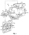
- a surgical light apparatus 30 includes a first arm assembly 32, a second arm assembly 34, a first lighthead 36 coupled to first arm assembly 32, and a second lighthead 38 coupled to second arm assembly 34 as shown in Fig. 1.
- First and second arm assemblies 32, 34 each couple to a common mounting apparatus 42 which is configured to mount to suitable support structure (not shown) associated with a ceiling 44.
- Each arm assembly 32, 34 includes an L-shaped upper or first arm 46, a lower or second arm 48, and a yoke 50.
- Each first arm 46 is independently pivotable relative to mounting apparatus 42 about a vertical pivot axis 52.
- Each second arm 48 is pivotable relative to the respective first arm 46 about a respective horizontal or main pivot axis 54 and about a respective vertical pivot axis 53 that is spaced from pivot axis 52.
- each yoke 50 is pivotable relative to the respective second arm 48 about a respective pivot axis 56 and each of lightheads 36, 38 is pivotable relative to the respective yoke 50 about a respective pivot axis 58.
- arm assemblies 32, 34 and lightheads 36, 38 are movable to a variety of positions relative to ceiling 44.
- Each lighthead 36, 38 includes a dome-shaped housing 60, a lens 62 through which light shines from the respective lighthead 36, 38, and a handle assembly 64 as shown in Fig. 1.
- Each handle assembly 64 includes a handle 66 which is grasped by a surgeon to move the respective lighthead 36, 38 and associated arm assembly 32, 34 to a desired position.
- Each lighthead 36, 38 includes one or more light bulbs (not shown) and each lighthead 36, 38 includes a reflector (not shown) that reflects light emanating from the at least one light bulb to illuminate a surgical site on a patient.
- Each lighthead 36, 38 also includes a light absorption filter (not shown) that is fabricated from specially formulated glass to filter most of the near and intermediate infra-red emissions from the at least one light bulb.
- Handle 66 of each handle assembly 64 is rotatable to move the at least one light bulb relative to the reflector to adjust the pattern size of reflected light that illuminates the surgical site.
- the pattern size may be thought of generally as the diameter of the area illuminated by the associated lighthead 36, 38.
- handle assembly 64 includes a button 74 at the bottom of handle 66 which is pressed to adjust the intensity level at which light emanates from the at least one light bulb.
- Handle assembly 64 includes an escutcheon 76 above handle 66.
- Handle assembly 64 further includes a first set of LED's 78 and a second set of LED's 80 that are visible on respective sides of escutcheon 76 to provide user information regarding the operation of the at least one light bulb and the intensity level at which light is emanating from the at least one light bulb.
- each of the at least one light bulb is a tungsten halogen lamp.
- Surgical light apparatus 30 includes a controller box 82, shown in Fig. 1, which is mounted to a wall 84 or other suitable structure and which is coupled electrically to surgical lightheads 36, 38 to control the operation of the at least one light bulb.
- Controller box 82 includes a control panel 86 having buttons 88 and sets of LED's 90 that are associated with each respective lighthead 36, 38.
- Each set of LED's 90 is arranged similarly and provides the same information as LED's 78, 80 of the respective lighthead 36, 38.
- each button 86 is pressed to change the light intensity of the at least one light bulb in the same manner that button 74 of the associated lighthead 36, 38 is pressed to change the light intensity of the at least one light bulb.
- Surgical light apparatus 30 optionally may include a task light 92, shown in Fig. 1, and controller box 82 optionally may include a button 94 that is pressed to turn task light 92 on and off.
- surgical light apparatus 30 includes two arm assemblies 32, 34 and two lightheads 36, 38 as shown in Fig. 1, it is within the scope of the invention as presently perceived for a different number of arm assemblies and corresponding lightheads to be provided.
- a surgical light apparatus having only one arm assembly and one corresponding lighthead and a surgical light apparatus having three or more arm assemblies and three or more corresponding lightheads are possible.
- Arm assembly 32 includes first arm 46 and second arm 48 as previously described. Arm assembly 32 further includes a first clevis 96 that attaches or otherwise appends to first arm 46 and a second clevis 98 that attaches or otherwise appends to second arm 48 as shown, for example, in Figs. 2 and 3.
- First clevis 96 includes a main body 100 and a pair of flanges 110 appended to main body 100 and extending therefrom in parallel relation so as to define a space 112 therebetween as shown in Fig. 2.
- Second clevis 98 includes a main body 114 and a pair of flanges 116 appended to main body 114 and extending therefrom in parallel relation so as to define a space 118 therebetween. Space 118 is larger than space 112.
- Flanges 110 of first clevis 96 are received in space 118 of second clevis 98 and flanges 110 each include an outer side face 120 that confronts a respective inner side face 122 of flanges 116 such that a minimal amount of clearance exists between side faces 120, 122.
- Flanges 110 each include a main aperture 124 and flanges 116 each include a main aperture 126 as shown in Fig. 2.
- a pair of pivot pins 128 is received by apertures 124, 126 to pivotably couple flanges 116 of second clevis 98 to respective flanges 110 of first clevis 96.
- Pivot pins 128 are spaced apart from one another such that a portion of space 112 defines a gap 130 between pivot pins 128 as shown best in Fig. 8.
- apertures 124 formed in flanges 110 of clevis 96 are threaded and apertures 126 formed in flanges 116 of clevis 98 are smooth.
- each pivot pin 128 includes an enlarged head portion 127 received in a respective aperture 126 and a threaded portion 129 received in a respective aperture 124.
- Apertures 124 are smaller in diameter than apertures 126 so that when pivot pins are threaded into apertures 124, head portions 127 engage a shoulder surface 131 of the respective flange 110.
- pivot pins 128 remain stationary along with flanges 110 of first clevis 96 while flanges 116 of second clevis 98 rotate relative to enlarged head portions 127 of pivot pins 128.
- Pivot pins 128, therefore, cooperate with apertures 126 to define main pivot axis 54 about which second clevis 98 and second arm 48 rotate.
- Each flange 116 is formed to include a recess 132, shown in Fig. 2, and arm assembly 32 includes a pair of cover plates 134 that are received in respective recesses 132 and that are fastened to the respective flange 116 by suitable fasteners, such as screws 136.
- Arm assembly 32 further includes a pair of cosmetic caps 138, shown in Figs. 1, 2 and 8, that are received in respective recesses 132 to shield respective cover plates 134 and screws 136 from view.
- Second arm 48 is a tubular member having an interior region 142 and second clevis 98 is formed to include an interior region 144 that extends through main body 114 into communication with space 118. Second arm 48 attaches to second clevis 98 such that interior region 142 communicates with interior region 144.
- Arm assembly 32 includes a counterbalancing assembly 140 that operates to counterbalance lighthead 32 so that lighthead 32 remains stationary after placement in a desired position. Respective portions of counterbalancing assembly 140 are positioned to lie in interior regions 142, 144 so as to be shielded from view by second arm 48 and second clevis 98.
- Counterbalancing assembly 140 includes a link 146, a rod 148, a spring 150, and an adjuster 152 as shown best in Fig. 2.
- Flanges 110 of first clevis 96 are each formed to include an aperture 154 that is spaced apart from and vertically above the respective main aperture 124.
- Link 146 includes a first end 156 formed with an aperture 158.
- Counterbalancing assembly 140 further includes a pivot pin 160 that is received by apertures 154 of flanges 110 and aperture 158 formed in first end 156 of link 146.
- pivot pin 160 couples link 146 to first clevis 96 for pivoting movement about a link pivot axis 162 defined by pivot pin 160.
- Each flange 110 of first clevis 96 includes an inner face 164 and link 146 includes a pair of vertical faces 166.
- First end 156 of link 146 is positioned to lie between inner faces 164 of flanges 110 such that a portion of each vertical face 166 faces toward a respective inner face 164 of the associated flange 110.
- Link 146 extends out of space 112 and away from first clevis 96 into interior region 144 of main body 114 of second clevis 98 as shown, for example, in Figs. 3 and 4.
- Rod 148 includes a first end face 168 formed with a slot 170 therein as shown in Fig. 2.
- Rod 148 is formed to include a pair of apertures 172 adjacent to first end face 168. Each aperture 172 communicates with slot 170.
- Link 146 includes a second end 174 formed with an aperture 176.
- Second end 174 of link 146 is positioned to lie in slot 170 formed in rod 148 and counterbalancing assembly 140 includes a pivot pin 178 received in apertures 172 or rod 148 and aperture 176 of link 146 to pivotably couple link 146 to rod 148.
- Rod 148 extends from link 146 through interior region 144 of main body 114 of second clevis 98 into interior region 142 of second arm 48 as shown in Figs. 3 and 4. Thus, one portion of rod 148 extends within interior region 144 of second clevis 98 and another portion of rod 148 extends within interior region 142 of second arm 48.
- Second clevis 98 includes an annular shoulder 180 having a journal aperture 182 formed therethrough as also shown in Figs. 3 and 4. Journal aperture 182 is sized so that a minimal amount of clearance exists between shoulder 180 and rod 148.
- link 146 pivots about link pivot axis 162 relative to first clevis 96 and pivots about pivot pin 178 relative to rod 148. Pivoting movement of link 146 causes rod 148 to move within journal aperture 182 relative to shoulder 180.
- Annular shoulder 180 is configured so that rod 148 is supported relative to second arm 48 in substantially coaxial relation therewith and so that a longitudinal axis 183 of rod 148 extends through main pivot axis 54 in perpendicular relation therewith.
- a separate bushing (not shown) may be mounted in journal aperture 182 of shoulder 180 to support rod 148 and to guide movement of rod 148 relative to shoulder 180.
- Rod 148 includes a second end face 184 that faces away from second clevis 98 as shown in Fig. 2.
- rod 148 is formed with a thread or threads 186 adjacent to second end face 184.
- Adjuster 152 includes a spring-engaging portion 188 and a rod-engaging portion 190 appended to spring-engaging portion 188 and extending axially therefrom toward first and second clevises 96, 98.
- Spring-engaging portion 188 of adjuster 152 includes a spring-engaging surface 192, shown in Figs. 3-5, that faces toward first and second clevises 96, 98 and an end surface 194, shown in Figs. 2-5, that faces away from first and second clevises 96, 98.
- rod-engaging portion 190 includes an end surface 196 that faces toward first and second clevis 96, 98 as shown in Figs. 3-5.
- Adjuster 152 includes a threaded bore 198 extending therethrough between end surfaces 194, 196. Adjuster 152 is threadedly coupled to rod 148 so that threads 186 of rod 148 engage threaded bore 198 of adjuster 152.
- spring 150 is a coil spring defining an interior region 200 and rod 148 extends through interior region 200 of spring 150.
- rod-engaging portion 190 of adjuster 152 is received in interior region 200 of spring 150 as shown in Figs. 3-5.
- Shoulder 180 includes a spring-engaging surface 210 as shown in Figs. 3 and 4.
- Spring 150 is compressed between spring-engaging surface 192 of adjuster 152 and spring-engaging surface 210 of shoulder 180.
- spring 150 acts between shoulder 180 and adjuster 152 to exert a force on rod 148 and link 146 to counterbalance lighthead 36.
- adjuster 152 is rotatable relative to rod 148 to change the amount by which spring 152 is compressed between spring-engaging surfaces 192, 210 thereby to change the amount of force exerted by spring 150 on rod 148 and link 146.
- arm mechanism 32 may include a tubular liner (not shown) that extends between shoulder 180 and adjuster 152 and that surrounds spring 150 to take up some of the circumferential clearance between spring 150 and second arm 48 to facilitate the coaxial positioning of spring 150 relative to second arm 48.
- Each of spring-engaging portion 188 and rod-engaging portion 190 of adjuster 152 are somewhat cylindrical in shape and adjuster 152 is configured such that a minimal amount of clearance exists between spring-engaging portion 188 and second arm 48.
- Spring-engaging portion 188 of adjuster 152 is formed to include a plurality of radially extending holes 212 and second arm 48 is formed to include a window 214, shown, for example, in Fig. 2, which allows access to adjuster 152.
- Arm assembly 32 includes a cover plate 216 that attaches to second arm 48 to cover window 214. When cover plate 216 is detached from second arm 48, an adjustment tool (not shown), such as a straight rod, is inserted though window 214 and into one of holes 212.
- the adjustment tool is then moved within window 214 to apply a torque to adjuster 152 to rotate adjuster 152 relative to rod 148.
- adjuster 152 advances on threads 186 of rod 148 toward first and second clevis 96, 98 or away from first and second clevises 96, 98 is dependent upon the direction that the adjustment tool is moved within window 214.
- window 214 is bounded by a pair of spaced apart, axially extending edges 218 and a pair of spaced apart, circumferentially extending edges 220 as shown best in Fig. 2.
- the spacing between edges 218 limits the amount by which adjuster 152 may be rotated relative to rod 148 during any one stroke of the adjustment tool between edges 218.
- the spacing between edges 220 which is indicated by reference numeral 222 in Figs. 3 and 4 limits the amount by which adjuster 152 is movable toward and away from first and second clevises 96, 98.
- adjuster 152 is movable relative to rod 148 between first and second axial positions (not shown) that are spaced apart by an amount that exceeds distance 222. This is due to the fact that, as second clevis 98 and second arm 48 pivot about main pivot axis 54, rod 148 and adjuster 152 are moved relative to second arm 148 by link 146 such that the distance between holes 212 and each of edges 220 varies.
- an arbitrary position of adjuster 152 relative to rod 148 is shown in Figs. 3 and 4 When second arm 48 is in a horizontal orientation, as shown in Fig.
- holes 212 are spaced apart from the edge 220 closest to first and second clevises 96, 98 by a distance 224.
- rod 148 is pulled by link 146 through journal aperture 182 such that spring 150 is further compressed between spring-engaging surfaces 192, 210 and such that the distance between holes 212 and the edge 220 closest to first and second clevises 96, 98 decreases.
- second clevis 98 and second arm 48 are in the position shown in Fig. 4
- holes 212 are spaced from the edge 220 closest to first and second clevises 96, 98 by a distance 228 which is smaller than distance 224.
- the adjustment tool may be used to rotate adjuster 152 relative to rod 148 such that holes 212 move away from the edge 220 closest to first and second clevises 96, 98 and toward the edge 220 furthest from first and second clevises 96, 98.
- adjuster 152 is adjusted relative to rod 148 in this manner and after second clevis 98 and second arm 48 are moved upwardly, for example, to a horizontal position, as shown in Fig. 5, holes 212 are no longer accessible through window 214.
- holes 212 become accessible through window 214 when second arm 48 is pivoted downwardly from the horizontal position of Fig. 5 back to the position of Fig. 4.
- adjuster 152 may be moved to a position on rod 148 such that holes 212 are accessible through window 214 when second arm 48 is in the horizontal position, shown in Fig. 3, and such that holes 212 are inaccessible through window 214 when second arm 48 is moved downwardly, for example, to the position shown in Fig. 4.
- adjuster 152 is movable axially on rod 148 by an amount that exceeds distance 222.
- Adjuster 152 Movement of adjuster 152 relative to rod 148 alters the amount by which spring 150 is compressed between spring-engaging surface 192 of adjuster 152 and spring-engaging surface 210 of shoulder 180.
- adjuster 152 is moved to a position relative to rod 148 such that surgical lighthead 36, yoke 50, second arm 48, second clevis 98, counterbalancing assembly 140, and other associated components of surgical light apparatus 30 are counterbalanced to remain stationary when placed in any desired position within a range of positions.
- Counterbalancing assembly 140 is configured so that second end face 184 of rod 148 is positioned to lie inside threaded bore 198 of adjuster 152 between end surfaces 194, 196.
- second arm 48 has a length that allows yoke 50 and lighthead 34 to be closer to main pivot axis 54 than would otherwise be possible if rod 148 were able to extend from adjuster 152 such that second end face 184 of rod 148 were positioned to lie between adjuster 152 and yoke 50.
- yoke 50 and lighthead 36 closer to main pivot axis 54 reduces the moment created by yoke 50 and lighthead 36 about main pivot axis 54 which means that counterbalancing assembly 140 is able to counterbalance yoke 50 and lighthead 36 with a smaller, and therefore less expensive, spring than would be the case if yoke 54 and lighthead 36 were further from main pivot axis 54.
- spring 150 is made of chrome silicon ASTM A401 material and has a spring rate of approximately three-hundred-fifty pounds per inch (18100 mm Hg). In addition, the ends of spring 150 are ground so as to abut respective spring-engaging surfaces 192, 210 flushly.
- link 146 and adjuster 152 are both made of 4140 steel material, rod 148 is made of 4130 steel material, and inner and outer clevises 96, 98 are each cast from aluminum. Of course, it is within the scope of the invention as presently perceived for these elements to be fabricated from other materials of suitable strength.
- Arm mechanism 32 is configured such that, in one preferred embodiment, second clevis 98 and second arm 48 are pivotable about main pivot axis 54 between first and second positions through a range of motion that exceeds one-hundred-eighty degrees.
- Main body 100 of first clevis 96 is formed to include a first stop surface 230 and a second stop surface 232 as shown in Fig. 6.
- main body 114 of second clevis 98 is formed to include a third stop surface 234 and a fourth stop surface 236 as also shown in Fig. 6.
- third stop surface 234 engages first stop surface 230 and when second clevis 98 and second arm 48 are in the second position, fourth stop surface 236 engages second stop surface 232.
- second clevis 98 and second arm 48 are in the first position, second arm 48 extends at an angle of approximately fifteen degrees above horizontal on one side of first clevis 96 and when second clevis 98 and second arm 48 are in the second position, second arm 48 extends at an angle 242 of approximately fifteen degrees above horizontal on another side of first clevis 96 as shown in Fig. 6
- second clevis 98 and second arm 48 are pivotable about main pivot axis 54 relative to first clevis 96 and first arm 46 through a range of motion of approximately two-hundred-ten degrees.
- link 146 moves through gap 130 between pivot pins 128.
- link 146 is positioned to lie in gap 130 between pivot pins 128.
- pivot pin 160 and the associated link pivot axis 162 vertically above pivot pins 128 and the associated main pivot axis 54, longitudinal axis 183 of rod 148 extends through both pivot axis 160 and pivot axis 54 when second clevis 98 and second arm 48 are in a vertical position aligned with first clevis 96 and first arm 46.
- spring 150 of counterbalancing assembly 140 exerts a substantially equivalent amount of force on rod 148 and link 146 when second clevis 98 and second arm 48 are moved from the vertical position by similar amounts either in direction 238 toward the first position or in direction 240 toward the second position.
- counterbalancing assembly 140 operates to counterbalance surgical lighthead 36 and other components of surgical light apparatus 30 associated with surgical lighthead 36 when second arm 48 and second clevis 98 are at any position between the first and second positions.
- arm assembly 32 can support any object of interest having a weight within limits dictated by counterbalancing assembly 140, it is anticipated that most users of arm assembly 32 will use arm assembly 32 to support a surgical lighthead.
- the meaning of the word "surgical lighthead” or “lighthead” as used in this specification and in the claims should be taken to include any object that is carried by arm assembly 32 either with or without yoke 50.
- Arm assembly 32 includes a clevis cover or space filler 244 as shown in Figs. 2 and 7-9.
- Space filler 244 includes a circular thin wall portion 246 and an arcuate rim 248 appended to the outer periphery of thin wall portion 246.
- Thin wall portion 246 is formed to include a central aperture 250 and an arcuate slot 252.
- Rim 248 and slot 252 are substantially concentric with central aperture 250 and slot 252 is positioned to lie between aperture 250 and rim 248 as shown best in Fig. 9.
- Rim 248 includes an outer circumferential edge 254 and an inner circumferential edge 256.
- rim 248 includes an arcuate surface 258 that extends between circumferential edges 254, 256 and that is spaced apart from and parallel with thin wall portion 246. Rim 248 further includes a pair of end edges 260 defining a link-receiving gap 262 therebetween as shown in Figs. 2 and 9.
- Space filler 244 is positioned to lie in space 112 between flanges 110 of first clevis 96 so that thin wall portion 246 is adjacent to inner face 164 of one of flanges 110 with a minimal amount of clearance therebetween and so that arcuate surface 258 of rim 248 is adjacent to the inner face 164 of the other of flanges 110 with a minimal amount of clearance therebetween as shown in Fig. 8.
- threaded portion 129 of one of pivot pins 128 is received in central aperture 250 of thin wall portion 248 so that space filler 244 is supported for pivoting movement about main pivot axis 54 relative to the flanges 110 of first clevis 96.
- Each of flanges 110 of first clevis 96 includes an outer circumferential edge 264 and each of flanges 116 of second clevis 98 includes an outer circumferential edge 266 as shown, for example, in Fig. 7.
- Circumferential edge 254 of rim 248 and circumferential edges 264, 266 of first and second clevises 96, 98 have substantially equivalent diameters.
- edge 254 of space filler 244 substantially spans space 112 between flanges 110 of first clevis 96 and edges 264 of flanges 110 cooperate with edge 254 of space filler 244 to substantially span space 118 between flanges 116 of second clevis 98.
- arm assembly 32 By configuring arm assembly 32 such that space 112 is spanned by rim 248 of space filler 244 and such that space 118 is spanned by rim 248 of space filler 244 and flanges 110 of first clevis 96, contamination is blocked from reaching space 112 and space 118.
- Pin 160 which pivotably couples link 146 to flanges 110 of first clevis 96 as previously described, extends through arcuate slot 252 formed in thin wall portion 246 of space filler 244. Thin wall portion 246 is positioned to lie between link 146 and inner face 164 of one of flanges 110 as shown in Fig. 8, and rim 248 substantially surrounds first end 156 of link 146 as shown in Fig. 6.
- Link 146 extends from pin 160 through link-receiving gap 262 of rim 248 and into interior region 144 of main body 114 of second clevis 98.
- Link 146 includes a flat edge 268 and a curved edge 270, each of which extend between first and second ends 156, 174 of link 146. Edge 270 is curved primarily to provide more room in space 112 between flanges 110 and interior region 144 of second clevis 98 for electrical wires (not shown) that are routed through arm mechanism 32 and yoke 50 to lighthead 36.
- one of edges 268, 270 engages a respective one of edges 260 of rim 248 to cause space filler 244 to pivot about main pivot axis 54 relative to flanges 110 of first clevis 96.
- Space filler 244 is configured so that link-receiving space 262 remains aligned with interior region 144 of second clevis 98 during movement of second clevis 98 and second arm 48 between the first and second positions.
- link 146 When the direction of pivoting movement of second clevis 98 and second arm 48 is reversed, link 146 separates away from one of edges 260 of rim 248 and moves toward the other of edges 260 of rim 248 and space filler 244 remains stationary relative to first clevis 96 until link 146 comes into contact with the other of edges 260 at which point space filler 244 pivots with second clevis 98 and second arm 48 relative to first clevis 96. However, because engagement between link 146 and space filler 244 causes space filler 244 to pivot about main pivot axis 54 during pivoting movement of second clevis 98 and second arm 48, space filler 244 pivots about main pivot axis 54 at a different rate than second clevis 98 and second arm 48.
- arm mechanism 332 which is similar to arm mechanism 32 is shown in Figs. 10 and 11. Many of the components of arm mechanism 332 are substantially similar to corresponding components of arm mechanism 32 and, therefore, are indicated with like reference numerals.
- arm mechanism 332 includes a counterbalancing assembly 140 having a link 146, a rod 148, and a spring 150.
- Arm mechanism 332 includes a first clevis 336 having a main body 338 and a pair of flanges 340 extending from main body 338. Main body 338 of first clevis 336 is attached or otherwise appended to first arm 46 as shown in Fig. 10.
- Arm mechanism 332 includes a second clevis 342 having a main body 344 and a pair of flanges 346 extending therefrom. Second clevis 342 is pivotably coupled to first clevis 336 by a pair of pivot pins 128 in substantially the same manner that second clevis 98 is pivotably coupled to first clevis 96.
- arm mechanism 32 is configured so that second clevis 98 and second arm 48 are able to pivot through a range of motion that exceeds one-hundred-eighty degrees as previously described, whereas arm mechanism 332 is configured so that second clevis 342 and the associated second arm (not shown) are able to pivot through a range of motion of approximately one-hundred-five degrees, as shown in Fig. 10.
- First clevis 336 includes a stop member 350 that is attached or otherwise adhered to main body 338 thereof as shown in Fig. 10. Stop member 350 includes a stop surface 352 and second clevis 342 includes a stop surface 354 that engages stop surface 352 when second clevis 342 and the associated second arm are in a raised or first position as also shown in Fig. 10 (in solid).
- First clevis 336 includes an amount of bridging material 360 that is appended to a portion of the outer periphery of each of flanges 340 of first clevis 336 as shown in Fig. 10, and that spans the space between flanges 340 of first clevis 336 as shown in Fig. 11.
- Bridging material 360 includes a stop surface 362 at the lower end thereof as shown in Figs. 10 and 11.
- Second clevis 342 includes a stop surface 364 that engages stop surface 362 when second clevis 342 and the associated second arm are in a second, substantially vertical or lowered position as shown in Fig. 10 (in phantom).
- link 146 moves into a gap defined between pivot pins 128.
- Second clevis 342 is formed to include an arcuate filler arm 380 that extends from main body 344 into the space defined between flanges 340 of first clevis 336 as shown best in Fig. 10. Filler arm 380 spans the space between flanges 340 thereby to block contamination from reaching the space between flanges 340 and the interior regions of first and second clevises 336, 342. Filler arm 380 includes a distal end surface 382 that is positioned to lie adjacent to stop surface 362 of bridging material 360 when second clevis 342 and the second arm associated therewith are in the first position as shown in Fig. 10 (in solid).
- Filler arm 380 includes an arcuate outer surface 384 and bridging material 360 includes an arcuate inner surface 386.
- Outer surface 384 of filler arm 380 confronts inner surface 386 of bridging material 360 with a minimal amount of clearance therebetween when second clevis 342 and the associated second arm are in the second position as shown in Fig. 10 (in phantom).
Landscapes
- Engineering & Computer Science (AREA)
- General Engineering & Computer Science (AREA)
- Mechanical Engineering (AREA)
- Physics & Mathematics (AREA)
- Spectroscopy & Molecular Physics (AREA)
- Manipulator (AREA)
- Non-Portable Lighting Devices Or Systems Thereof (AREA)
- Surgical Instruments (AREA)
- Led Devices (AREA)
- Measurement Of The Respiration, Hearing Ability, Form, And Blood Characteristics Of Living Organisms (AREA)
- Laser Surgery Devices (AREA)
Abstract
Description
- The present invention relates to a surgical light apparatus, and particularly, to a support arm for the surgical light apparatus. More particularly, the present invention relates to a jointed support arm that permits movement of a lighthead of the surgical light apparatus to various positions and that counterbalances the weight of the surgical lighthead.
- Surgical lights used in hospital operating rooms to illuminate surgical sites on patients are known. Many surgical lights include a surgical lighthead containing a light source and an arm mechanism configured to support the surgical lighthead relative to a ceiling of the operating room. Such arm mechanisms typically include one or more joints which allow the surgical lighthead to be moved in plural degrees of freedom within the operating room to various positions so that the light source of the surgical light illuminates a surgical site on a patient in a desired manner. It is desirable for the arm mechanism of the surgical light to counterbalance the associated surgical lighthead when the surgical lighthead is at any position within a range of positions.
- DE-U-8309857 discloses a generic support for a surgical lighthead with a first generally vertical arm having a second arm pivotally connected to its lower end. The lighthead is carried by the second arm between first and second positions approximately 20° above and below the horizontal.
- US 2941776 discloses a counterbalancing mechanism for supporting an object at a number of different levels. One link of a parallel motion linkage constitutes a housing for the mechanism and the other link is enclosed by a compression spring mounted in the housing such that it maintains the enclosed link under tension.
- According to the present invention, an arm assembly for supporting a surgical lighthead of a surgical light apparatus includes a first arm and a first clevis appended to the first arm. The first clevis has a pair of separated first flanges. The first clevis further includes a first stop surface and a second stop surface. The arm assembly includes a second arm which is formed to include an interior region. The surgical lighthead is supported by the second arm. A second clevis is appended to the second arm and has a pair of separated second flanges. The second clevis further includes a third stop surface and a fourth stop surface.
- A pair of pivot pins pivotably couples each of the pair of second flanges to a respective one of the first flanges so that the second arm and second clevis are pivotable about a main pivot axis relative to the first arm and first clevis. The pivot pins are spaced apart to define a gap therebetween. A rod extends within the interior region of the second arm. The arm assembly includes a link coupled to the rod and pivotably coupled to the first clevis for pivoting movement about a link pivot axis that is spaced apart from the main pivot axis. A spring extends within the interior region of the second arm and exerts a force on the rod and the link to counterbalance the surgical lighthead.
- The arm assembly is configured so that the second arm and second clevis are pivotable about the main pivot axis relative to the first arm and first clevis between a first position in which the third stop surface engages the first stop surface to limit pivoting movement of the second clevis and second arm in a first direction and a second position in which the fourth stop surface engages the second stop surface to limit pivoting movement of the second clevis and second arm in a second direction. The link moves into the gap between the pair of pivot pins during movement of the second arm and second clevis between the first position and the second position.
- In preferred embodiments, the arm assembly includes an adjuster mounted on the rod. The adjuster includes a spring-engaging portion that engages the spring to compress the spring against the second clevis. The adjuster is movable to change the force exerted by the spring on the rod and the link to counterbalance the surgical lighthead. Also in preferred embodiments, the arm assembly includes a space filler that is positioned to lie between the first flanges of the first clevis. The space filler includes a rim that spans the space between the first flanges. In addition, the rim of the space filler cooperates with the first flanges to span the space between the second flanges of the second clevis.
- Additional features and advantages of the present invention will become apparent to those skilled in the art upon consideration of the following detailed description of preferred embodiments exemplifying the best mode of carrying out the invention as presently perceived.
- The detailed description particularly refers to the accompanying figures in which:
- Fig. 1 is an isometric view of a surgical light apparatus in accordance with the present invention showing a first surgical lighthead suspended from a ceiling of a hospital room by a first arm assembly, a second surgical lighthead suspended from the ceiling of the hospital room by a second arm assembly, and a light-controller box mounted to a wall of the hospital room;
- Fig. 2 is an exploded view of the first arm assembly of Fig. 1 showing a vertically extending first arm, a first clevis arranged for attachment to a bottom portion of the first arm, a second clevis arranged for attachment to the first clevis by a pair of pivot pins, a yoke arranged for attachment to the first surgical lighthead, a tubular second arm having a first end that attaches to the yoke and a second end that attaches to the second clevis, and components of a counterbalancing mechanism arranged for insertion into respective interior regions of the second arm and second clevis;
- Fig. 3 is a side elevation view of the first arm mechanism of Fig. 2, with portions broken away, showing the counterbalancing mechanism including a coil spring extending within an interior region of the second arm, a rod extending through the coil spring within the interior region of the second arm, a link having one end pivotably coupled to one end of the rod and having another end pivotably coupled to the first clevis, and an adjuster bolt threadedly coupled to another end of the rod, the adjuster bolt including a plurality of small holes that are accessible through a window formed in the second arm;
- Fig. 4 is a side elevation view similar to Fig. 3 showing the second arm and second clevis pivoting in the direction of the double arrow relative to the first clevis, the rod moving relative to the second arm as the second arm and second clevis pivot in the direction of the double arrow so that the spring is further compressed between the adjuster bolt and a shoulder of the second clevis;
- Fig. 5 is a side elevation view of a portion of the second arm in a horizontal position showing the adjuster bolt adjusted relative to the rod such that the small holes of the adjuster bolt are inaccessible through the window in the arm and such that the small holes would become accessible through the window in the second arm if the second arm were pivoted downwardly away from the horizontal position by a sufficient amount;
- Fig. 6 is a side elevation view of a portion of the first arm mechanism showing the second arm and second clevis in a horizontal position (in solid), the second arm and second clevis being pivotable from the solid-line horizontal position in a counterclockwise direction to a first position (in phantom) in which a stop edge of the second clevis engages an associated stop edge of the first clevis, and the second arm and second clevis being pivotable from the solid-line horizontal position in a clockwise direction through another horizontal position (in phantom) into a second position (in phantom) in which another stop edge of the second clevis engages an associated stop edge of the first clevis;
- Fig. 7 is a rear view of the arm mechanism of Fig. 6 showing a pair of flanges of the first clevis positioned to lie between a pair of flanges of the second clevis and showing a space filler positioned to lie between the pair of flanges of the first clevis;
- Fig. 8 is a sectional view of the arm mechanism of Fig. 6, taken along line 8-8, showing the link of the counterbalancing assembly pinned to the flanges of the first clevis above the pair of pivot pins coupling the second clevis to the first clevis;
- Fig. 9 is a side elevation view of the space filler showing an arcuate slot and a central aperture formed in a thin wall of the space filler and showing an arcuate rim of the space filler appended to an outer periphery of the thin wall;
- Fig. 10 is side elevation view of a portion of an alternative embodiment arm mechanism in accordance with the present invention, with portions broken away, showing a second clevis of the alternative embodiment arm mechanism in a raised or first position (in solid) in which a stop edge of the second clevis engages an associated stop member of a first clevis of the alternative embodiment arm mechanism, and the second clevis being pivotable from the raised position in a clockwise direction (indicated by the phantom double arrow) into a lowered or second position (in phantom) in which another stop edge of the second clevis engages an associated stop edge of the first clevis; and
- Fig. 11 is a rear view of a portion of the alternative embodiment arm mechanism of Fig. 10 showing the second clevis in an intermediate position between the raised and lowered positions.
- A
surgical light apparatus 30 includes afirst arm assembly 32, asecond arm assembly 34, afirst lighthead 36 coupled tofirst arm assembly 32, and asecond lighthead 38 coupled tosecond arm assembly 34 as shown in Fig. 1. First and second arm assemblies 32, 34 each couple to acommon mounting apparatus 42 which is configured to mount to suitable support structure (not shown) associated with aceiling 44. Eacharm assembly first arm 46, a lower orsecond arm 48, and ayoke 50. Eachfirst arm 46 is independently pivotable relative to mountingapparatus 42 about avertical pivot axis 52. Eachsecond arm 48 is pivotable relative to the respectivefirst arm 46 about a respective horizontal ormain pivot axis 54 and about a respectivevertical pivot axis 53 that is spaced frompivot axis 52. In addition, eachyoke 50 is pivotable relative to the respectivesecond arm 48 about arespective pivot axis 56 and each oflightheads respective yoke 50 about arespective pivot axis 58. Thus,arm assemblies lightheads ceiling 44. - Each
lighthead shaped housing 60, alens 62 through which light shines from therespective lighthead handle assembly 64 as shown in Fig. 1. Eachhandle assembly 64 includes ahandle 66 which is grasped by a surgeon to move therespective lighthead arm assembly lighthead lighthead lighthead -
Handle 66 of eachhandle assembly 64 is rotatable to move the at least one light bulb relative to the reflector to adjust the pattern size of reflected light that illuminates the surgical site. The pattern size may be thought of generally as the diameter of the area illuminated by the associatedlighthead handle assembly 64 includes abutton 74 at the bottom ofhandle 66 which is pressed to adjust the intensity level at which light emanates from the at least one light bulb.Handle assembly 64 includes anescutcheon 76 abovehandle 66.Handle assembly 64 further includes a first set of LED's 78 and a second set of LED's 80 that are visible on respective sides ofescutcheon 76 to provide user information regarding the operation of the at least one light bulb and the intensity level at which light is emanating from the at least one light bulb. In preferred embodiments, each of the at least one light bulb is a tungsten halogen lamp. -
Surgical light apparatus 30 includes acontroller box 82, shown in Fig. 1, which is mounted to awall 84 or other suitable structure and which is coupled electrically tosurgical lightheads Controller box 82 includes acontrol panel 86 havingbuttons 88 and sets of LED's 90 that are associated with eachrespective lighthead respective lighthead button 86 is pressed to change the light intensity of the at least one light bulb in the same manner thatbutton 74 of the associatedlighthead respective handle assembly 64 orcontroller box 82. Surgicallight apparatus 30 optionally may include a task light 92, shown in Fig. 1, andcontroller box 82 optionally may include abutton 94 that is pressed to turn task light 92 on and off. - Other features of surgical
light apparatus 30 are discussed and shown in detail in co-pending U.S. patent applications Serial No. 09/050,265 entitled Reflector for Surgical Light Apparatus; Serial No. 09/050,529 entitled Surgical Light Apparatus with Improved Cooling; Serial No. 09/050,534 Controls for Surgical Light Apparatus; and Serial No. 09/050, 576 entitled Task Light for Surgical Light Apparatus, all of which are hereby incorporated by reference. - The description below of
first arm assembly 32 and the operation offirst arm assembly 32 applies as well tosecond arm assembly 34 and the operation ofsecond arm assembly 34 unless specifically noted otherwise. In addition, although surgicallight apparatus 30 includes twoarm assemblies lightheads -
Arm assembly 32 includesfirst arm 46 andsecond arm 48 as previously described.Arm assembly 32 further includes afirst clevis 96 that attaches or otherwise appends tofirst arm 46 and asecond clevis 98 that attaches or otherwise appends tosecond arm 48 as shown, for example, in Figs. 2 and 3.First clevis 96 includes amain body 100 and a pair offlanges 110 appended tomain body 100 and extending therefrom in parallel relation so as to define aspace 112 therebetween as shown in Fig. 2.Second clevis 98 includes amain body 114 and a pair offlanges 116 appended tomain body 114 and extending therefrom in parallel relation so as to define aspace 118 therebetween.Space 118 is larger thanspace 112. -
Flanges 110 offirst clevis 96 are received inspace 118 ofsecond clevis 98 andflanges 110 each include anouter side face 120 that confronts a respective inner side face 122 offlanges 116 such that a minimal amount of clearance exists between side faces 120, 122.Flanges 110 each include amain aperture 124 andflanges 116 each include amain aperture 126 as shown in Fig. 2. A pair of pivot pins 128 is received byapertures pivotably couple flanges 116 ofsecond clevis 98 torespective flanges 110 offirst clevis 96. Pivot pins 128 are spaced apart from one another such that a portion ofspace 112 defines agap 130 between pivot pins 128 as shown best in Fig. 8. - In preferred embodiments,
apertures 124 formed inflanges 110 ofclevis 96 are threaded andapertures 126 formed inflanges 116 ofclevis 98 are smooth. In addition, eachpivot pin 128 includes anenlarged head portion 127 received in arespective aperture 126 and a threadedportion 129 received in arespective aperture 124.Apertures 124 are smaller in diameter thanapertures 126 so that when pivot pins are threaded intoapertures 124,head portions 127 engage ashoulder surface 131 of therespective flange 110. Assecond clevis 98 andsecond arm 48 pivot aboutmain pivot axis 54, pivot pins 128 remain stationary along withflanges 110 offirst clevis 96 whileflanges 116 ofsecond clevis 98 rotate relative toenlarged head portions 127 of pivot pins 128. Pivot pins 128, therefore, cooperate withapertures 126 to definemain pivot axis 54 about whichsecond clevis 98 andsecond arm 48 rotate. Eachflange 116 is formed to include arecess 132, shown in Fig. 2, andarm assembly 32 includes a pair ofcover plates 134 that are received inrespective recesses 132 and that are fastened to therespective flange 116 by suitable fasteners, such as screws 136.Arm assembly 32 further includes a pair ofcosmetic caps 138, shown in Figs. 1, 2 and 8, that are received inrespective recesses 132 to shieldrespective cover plates 134 andscrews 136 from view. -
Second arm 48 is a tubular member having aninterior region 142 andsecond clevis 98 is formed to include aninterior region 144 that extends throughmain body 114 into communication withspace 118.Second arm 48 attaches tosecond clevis 98 such thatinterior region 142 communicates withinterior region 144.Arm assembly 32 includes a counterbalancingassembly 140 that operates to counterbalancelighthead 32 so thatlighthead 32 remains stationary after placement in a desired position. Respective portions of counterbalancingassembly 140 are positioned to lie ininterior regions second arm 48 andsecond clevis 98. - Counterbalancing
assembly 140 includes alink 146, arod 148, aspring 150, and anadjuster 152 as shown best in Fig. 2.Flanges 110 offirst clevis 96 are each formed to include anaperture 154 that is spaced apart from and vertically above the respectivemain aperture 124.Link 146 includes afirst end 156 formed with anaperture 158. Counterbalancingassembly 140 further includes apivot pin 160 that is received byapertures 154 offlanges 110 andaperture 158 formed infirst end 156 oflink 146. Thus,pivot pin 160 couples link 146 tofirst clevis 96 for pivoting movement about alink pivot axis 162 defined bypivot pin 160. Eachflange 110 offirst clevis 96 includes aninner face 164 and link 146 includes a pair of vertical faces 166.First end 156 oflink 146 is positioned to lie betweeninner faces 164 offlanges 110 such that a portion of eachvertical face 166 faces toward a respectiveinner face 164 of the associatedflange 110. -
Link 146 extends out ofspace 112 and away fromfirst clevis 96 intointerior region 144 ofmain body 114 ofsecond clevis 98 as shown, for example, in Figs. 3 and 4.Rod 148 includes afirst end face 168 formed with aslot 170 therein as shown in Fig. 2.Rod 148 is formed to include a pair ofapertures 172 adjacent tofirst end face 168. Eachaperture 172 communicates withslot 170.Link 146 includes asecond end 174 formed with anaperture 176.Second end 174 oflink 146 is positioned to lie inslot 170 formed inrod 148 and counterbalancingassembly 140 includes apivot pin 178 received inapertures 172 orrod 148 andaperture 176 oflink 146 to pivotably couple link 146 torod 148. -
Rod 148 extends fromlink 146 throughinterior region 144 ofmain body 114 ofsecond clevis 98 intointerior region 142 ofsecond arm 48 as shown in Figs. 3 and 4. Thus, one portion ofrod 148 extends withininterior region 144 ofsecond clevis 98 and another portion ofrod 148 extends withininterior region 142 ofsecond arm 48.Second clevis 98 includes anannular shoulder 180 having ajournal aperture 182 formed therethrough as also shown in Figs. 3 and 4.Journal aperture 182 is sized so that a minimal amount of clearance exists betweenshoulder 180 androd 148. - As
second arm 48 andsecond clevis 98 pivot aboutmain axis 54, link 146 pivots aboutlink pivot axis 162 relative tofirst clevis 96 and pivots aboutpivot pin 178 relative torod 148. Pivoting movement oflink 146 causesrod 148 to move withinjournal aperture 182 relative toshoulder 180.Annular shoulder 180 is configured so thatrod 148 is supported relative tosecond arm 48 in substantially coaxial relation therewith and so that alongitudinal axis 183 ofrod 148 extends throughmain pivot axis 54 in perpendicular relation therewith. In alternative embodiments, a separate bushing (not shown) may be mounted injournal aperture 182 ofshoulder 180 to supportrod 148 and to guide movement ofrod 148 relative toshoulder 180. -
Rod 148 includes asecond end face 184 that faces away fromsecond clevis 98 as shown in Fig. 2. In addition,rod 148 is formed with a thread orthreads 186 adjacent tosecond end face 184.Adjuster 152 includes a spring-engagingportion 188 and a rod-engagingportion 190 appended to spring-engagingportion 188 and extending axially therefrom toward first andsecond clevises portion 188 ofadjuster 152 includes a spring-engagingsurface 192, shown in Figs. 3-5, that faces toward first andsecond clevises end surface 194, shown in Figs. 2-5, that faces away from first andsecond clevises portion 190 includes anend surface 196 that faces toward first andsecond clevis Adjuster 152 includes a threadedbore 198 extending therethrough between end surfaces 194, 196.Adjuster 152 is threadedly coupled torod 148 so thatthreads 186 ofrod 148 engage threadedbore 198 ofadjuster 152. - In preferred embodiments,
spring 150 is a coil spring defining aninterior region 200 androd 148 extends throughinterior region 200 ofspring 150. In addition, rod-engagingportion 190 ofadjuster 152 is received ininterior region 200 ofspring 150 as shown in Figs. 3-5.Shoulder 180 includes a spring-engagingsurface 210 as shown in Figs. 3 and 4.Spring 150 is compressed between spring-engagingsurface 192 ofadjuster 152 and spring-engagingsurface 210 ofshoulder 180. Thus,spring 150 acts betweenshoulder 180 andadjuster 152 to exert a force onrod 148 and link 146 to counterbalancelighthead 36. In addition,adjuster 152 is rotatable relative torod 148 to change the amount by whichspring 152 is compressed between spring-engagingsurfaces spring 150 onrod 148 and link 146. In alternative embodiments,arm mechanism 32 may include a tubular liner (not shown) that extends betweenshoulder 180 andadjuster 152 and that surroundsspring 150 to take up some of the circumferential clearance betweenspring 150 andsecond arm 48 to facilitate the coaxial positioning ofspring 150 relative tosecond arm 48. - Each of spring-engaging
portion 188 and rod-engagingportion 190 ofadjuster 152 are somewhat cylindrical in shape andadjuster 152 is configured such that a minimal amount of clearance exists between spring-engagingportion 188 andsecond arm 48. Spring-engagingportion 188 ofadjuster 152 is formed to include a plurality of radially extendingholes 212 andsecond arm 48 is formed to include awindow 214, shown, for example, in Fig. 2, which allows access toadjuster 152.Arm assembly 32 includes acover plate 216 that attaches tosecond arm 48 to coverwindow 214. Whencover plate 216 is detached fromsecond arm 48, an adjustment tool (not shown), such as a straight rod, is inserted thoughwindow 214 and into one ofholes 212. The adjustment tool is then moved withinwindow 214 to apply a torque toadjuster 152 to rotateadjuster 152 relative torod 148. Whetheradjuster 152 advances onthreads 186 ofrod 148 toward first andsecond clevis second clevises window 214. - In preferred embodiments,
window 214 is bounded by a pair of spaced apart, axially extendingedges 218 and a pair of spaced apart, circumferentially extendingedges 220 as shown best in Fig. 2. The spacing betweenedges 218 limits the amount by whichadjuster 152 may be rotated relative torod 148 during any one stroke of the adjustment tool between edges 218. In addition, the spacing betweenedges 220, which is indicated byreference numeral 222 in Figs. 3 and 4, limits the amount by whichadjuster 152 is movable toward and away from first andsecond clevises - It will be understood that, although
edges 220 are spaced apart bydistance 222,adjuster 152 is movable relative torod 148 between first and second axial positions (not shown) that are spaced apart by an amount that exceedsdistance 222. This is due to the fact that, assecond clevis 98 andsecond arm 48 pivot aboutmain pivot axis 54,rod 148 andadjuster 152 are moved relative tosecond arm 148 bylink 146 such that the distance betweenholes 212 and each ofedges 220 varies. For example, an arbitrary position ofadjuster 152 relative torod 148 is shown in Figs. 3 and 4 Whensecond arm 48 is in a horizontal orientation, as shown in Fig. 3, holes 212 are spaced apart from theedge 220 closest to first andsecond clevises second clevis 98 andsecond arm 48 rotate aboutmain pivot axis 54 in the direction ofdouble arrow 226, shown in Fig. 4,rod 148 is pulled bylink 146 throughjournal aperture 182 such thatspring 150 is further compressed between spring-engagingsurfaces holes 212 and theedge 220 closest to first andsecond clevises second clevis 98 andsecond arm 48 are in the position shown in Fig. 4, holes 212 are spaced from theedge 220 closest to first andsecond clevises distance 228 which is smaller than distance 224. - When
second clevis 98 andsecond arm 48 are held in the position shown in Fig. 4, the adjustment tool may be used to rotateadjuster 152 relative torod 148 such that holes 212 move away from theedge 220 closest to first andsecond clevises edge 220 furthest from first andsecond clevises adjuster 152 is adjusted relative torod 148 in this manner and aftersecond clevis 98 andsecond arm 48 are moved upwardly, for example, to a horizontal position, as shown in Fig. 5, holes 212 are no longer accessible throughwindow 214. Of course, holes 212 become accessible throughwindow 214 whensecond arm 48 is pivoted downwardly from the horizontal position of Fig. 5 back to the position of Fig. 4. - It will be understood that
adjuster 152 may be moved to a position onrod 148 such that holes 212 are accessible throughwindow 214 whensecond arm 48 is in the horizontal position, shown in Fig. 3, and such that holes 212 are inaccessible throughwindow 214 whensecond arm 48 is moved downwardly, for example, to the position shown in Fig. 4. Thus, by articulatingsecond arm 48 andsecond clevis 98 relative tofirst arm 46 andfirst clevis 96 and by using the adjustment tool to make appropriate adjustments ofadjuster 152 relative torod 148 whenholes 212 are accessible throughwindow 212,adjuster 152 is movable axially onrod 148 by an amount that exceedsdistance 222. - Movement of
adjuster 152 relative torod 148 alters the amount by whichspring 150 is compressed between spring-engagingsurface 192 ofadjuster 152 and spring-engagingsurface 210 ofshoulder 180. In use,adjuster 152 is moved to a position relative torod 148 such thatsurgical lighthead 36,yoke 50,second arm 48,second clevis 98, counterbalancingassembly 140, and other associated components of surgicallight apparatus 30 are counterbalanced to remain stationary when placed in any desired position within a range of positions. Counterbalancingassembly 140 is configured so thatsecond end face 184 ofrod 148 is positioned to lie inside threaded bore 198 ofadjuster 152 between end surfaces 194, 196. - By configuring
adjuster 152 such thatsecond end face 184 ofrod 148 is never in a position betweenend face 194 ofadjuster 152 andyoke 50,second arm 48 has a length that allowsyoke 50 andlighthead 34 to be closer tomain pivot axis 54 than would otherwise be possible ifrod 148 were able to extend fromadjuster 152 such thatsecond end face 184 ofrod 148 were positioned to lie betweenadjuster 152 andyoke 50. Havingyoke 50 andlighthead 36 closer tomain pivot axis 54 reduces the moment created byyoke 50 andlighthead 36 aboutmain pivot axis 54 which means that counterbalancingassembly 140 is able to counterbalanceyoke 50 andlighthead 36 with a smaller, and therefore less expensive, spring than would be the case ifyoke 54 andlighthead 36 were further frommain pivot axis 54. - In preferred embodiments,
spring 150 is made of chrome silicon ASTM A401 material and has a spring rate of approximately three-hundred-fifty pounds per inch (18100 mm Hg). In addition, the ends ofspring 150 are ground so as to abut respective spring-engagingsurfaces adjuster 152 are both made of 4140 steel material,rod 148 is made of 4130 steel material, and inner andouter clevises -
Arm mechanism 32 is configured such that, in one preferred embodiment,second clevis 98 andsecond arm 48 are pivotable aboutmain pivot axis 54 between first and second positions through a range of motion that exceeds one-hundred-eighty degrees.Main body 100 offirst clevis 96 is formed to include afirst stop surface 230 and asecond stop surface 232 as shown in Fig. 6. In addition,main body 114 ofsecond clevis 98 is formed to include athird stop surface 234 and afourth stop surface 236 as also shown in Fig. 6. Whensecond clevis 98 andsecond arm 48 are in the first position,third stop surface 234 engagesfirst stop surface 230 and whensecond clevis 98 andsecond arm 48 are in the second position,fourth stop surface 236 engagessecond stop surface 232. - Engagement between stop surfaces 230, 234 prevents
clevis 98 andsecond arm 48 from pivoting upwardly past the first position in the direction ofarrow 238 and engagement between stop surfaces 232, 236 preventsclevis 98 andsecond arm 48 from pivoting upwardly past the second position in the direction ofarrow 240. Whensecond clevis 98 andsecond arm 48 are in the first position,second arm 48 extends at an angle of approximately fifteen degrees above horizontal on one side offirst clevis 96 and whensecond clevis 98 andsecond arm 48 are in the second position,second arm 48 extends at anangle 242 of approximately fifteen degrees above horizontal on another side offirst clevis 96 as shown in Fig. 6 Thus, in preferred embodiments,second clevis 98 andsecond arm 48 are pivotable aboutmain pivot axis 54 relative tofirst clevis 96 andfirst arm 46 through a range of motion of approximately two-hundred-ten degrees. - As
second clevis 98 andsecond arm 48 move between the first and second positions, link 146 moves throughgap 130 between pivot pins 128. Whensecond clevis 98 andsecond arm 48 are aligned vertically withfirst clevis 96 andfirst arm 46, link 146 is positioned to lie ingap 130 between pivot pins 128. By havingpivot pin 160 and the associatedlink pivot axis 162 vertically above pivot pins 128 and the associatedmain pivot axis 54,longitudinal axis 183 ofrod 148 extends through bothpivot axis 160 and pivotaxis 54 whensecond clevis 98 andsecond arm 48 are in a vertical position aligned withfirst clevis 96 andfirst arm 46. In addition, by havingpivot pin 160 and the associatedlink pivot axis 162 vertically above pivot pins 128 and the associatedmain pivot axis 54,spring 150 of counterbalancingassembly 140 exerts a substantially equivalent amount of force onrod 148 and link 146 whensecond clevis 98 andsecond arm 48 are moved from the vertical position by similar amounts either indirection 238 toward the first position or indirection 240 toward the second position. - In preferred embodiments, counterbalancing
assembly 140 operates to counterbalancesurgical lighthead 36 and other components of surgicallight apparatus 30 associated withsurgical lighthead 36 whensecond arm 48 andsecond clevis 98 are at any position between the first and second positions. In addition, in preferred embodiments,longitudinal axis 183 ofrod 148 andaxis 58, about which lighthead 36 pivots relative toyoke 50, intersect at the center of gravity (not shown) ofsurgical lighthead 36. By havingaxis 183 intersecting withaxis 58 at the center of gravity oflighthead 36, the moment created bylighthead 36 andyoke 50 aboutmain pivot axis 54, whensecond arm 48 andsecond clevis 98 are stationary in any particular position between the first and second positions, is substantially constant independent of the position ofyoke 50 relative tosecond arm 48 and independent of the position oflighthead 36 relative toyoke 50. If the center of gravity oflighthead 36 is offset from either ofaxes arm assembly 32assists counterbalancing assembly 140 to compensate for this offset so thatlighthead 36 and other components of surgicallight apparatus 30 associated withlighthead 36 still remain counterbalanced. - While
arm assembly 32 can support any object of interest having a weight within limits dictated by counterbalancingassembly 140, it is anticipated that most users ofarm assembly 32 will usearm assembly 32 to support a surgical lighthead. Thus, the meaning of the word "surgical lighthead" or "lighthead" as used in this specification and in the claims should be taken to include any object that is carried byarm assembly 32 either with or withoutyoke 50. -
Arm assembly 32 includes a clevis cover orspace filler 244 as shown in Figs. 2 and 7-9.Space filler 244 includes a circularthin wall portion 246 and anarcuate rim 248 appended to the outer periphery ofthin wall portion 246.Thin wall portion 246 is formed to include acentral aperture 250 and anarcuate slot 252.Rim 248 and slot 252 are substantially concentric withcentral aperture 250 andslot 252 is positioned to lie betweenaperture 250 andrim 248 as shown best in Fig. 9.Rim 248 includes an outercircumferential edge 254 and an innercircumferential edge 256. In addition,rim 248 includes anarcuate surface 258 that extends betweencircumferential edges thin wall portion 246.Rim 248 further includes a pair of end edges 260 defining a link-receivinggap 262 therebetween as shown in Figs. 2 and 9. -
Space filler 244 is positioned to lie inspace 112 betweenflanges 110 offirst clevis 96 so thatthin wall portion 246 is adjacent toinner face 164 of one offlanges 110 with a minimal amount of clearance therebetween and so thatarcuate surface 258 ofrim 248 is adjacent to theinner face 164 of the other offlanges 110 with a minimal amount of clearance therebetween as shown in Fig. 8. In addition, threadedportion 129 of one of pivot pins 128 is received incentral aperture 250 ofthin wall portion 248 so thatspace filler 244 is supported for pivoting movement aboutmain pivot axis 54 relative to theflanges 110 offirst clevis 96. - Each of
flanges 110 offirst clevis 96 includes an outercircumferential edge 264 and each offlanges 116 ofsecond clevis 98 includes an outercircumferential edge 266 as shown, for example, in Fig. 7.Circumferential edge 254 ofrim 248 andcircumferential edges second clevises space filler 244 substantially spansspace 112 betweenflanges 110 offirst clevis 96 andedges 264 offlanges 110 cooperate withedge 254 ofspace filler 244 to substantially spanspace 118 betweenflanges 116 ofsecond clevis 98. By configuringarm assembly 32 such thatspace 112 is spanned byrim 248 ofspace filler 244 and such thatspace 118 is spanned byrim 248 ofspace filler 244 andflanges 110 offirst clevis 96, contamination is blocked from reachingspace 112 andspace 118. -
Pin 160, which pivotably couples link 146 toflanges 110 offirst clevis 96 as previously described, extends througharcuate slot 252 formed inthin wall portion 246 ofspace filler 244.Thin wall portion 246 is positioned to lie betweenlink 146 andinner face 164 of one offlanges 110 as shown in Fig. 8, and rim 248 substantially surroundsfirst end 156 oflink 146 as shown in Fig. 6.Link 146 extends frompin 160 through link-receivinggap 262 ofrim 248 and intointerior region 144 ofmain body 114 ofsecond clevis 98.Link 146 includes aflat edge 268 and acurved edge 270, each of which extend between first and second ends 156, 174 oflink 146.Edge 270 is curved primarily to provide more room inspace 112 betweenflanges 110 andinterior region 144 ofsecond clevis 98 for electrical wires (not shown) that are routed througharm mechanism 32 andyoke 50 tolighthead 36. - As
second clevis 98 andsecond arm 48 pivot indirections edges edges 260 ofrim 248 to causespace filler 244 to pivot aboutmain pivot axis 54 relative toflanges 110 offirst clevis 96.Space filler 244 is configured so that link-receivingspace 262 remains aligned withinterior region 144 ofsecond clevis 98 during movement ofsecond clevis 98 andsecond arm 48 between the first and second positions. When the direction of pivoting movement ofsecond clevis 98 andsecond arm 48 is reversed, link 146 separates away from one ofedges 260 ofrim 248 and moves toward the other ofedges 260 ofrim 248 andspace filler 244 remains stationary relative tofirst clevis 96 untillink 146 comes into contact with the other ofedges 260 at which pointspace filler 244 pivots withsecond clevis 98 andsecond arm 48 relative tofirst clevis 96. However, because engagement betweenlink 146 andspace filler 244 causesspace filler 244 to pivot aboutmain pivot axis 54 during pivoting movement ofsecond clevis 98 andsecond arm 48,space filler 244 pivots aboutmain pivot axis 54 at a different rate thansecond clevis 98 andsecond arm 48. - An alternative
embodiment arm mechanism 332 which is similar toarm mechanism 32 is shown in Figs. 10 and 11. Many of the components ofarm mechanism 332 are substantially similar to corresponding components ofarm mechanism 32 and, therefore, are indicated with like reference numerals. For example,arm mechanism 332 includes a counterbalancingassembly 140 having alink 146, arod 148, and aspring 150.Arm mechanism 332 includes afirst clevis 336 having amain body 338 and a pair offlanges 340 extending frommain body 338.Main body 338 offirst clevis 336 is attached or otherwise appended tofirst arm 46 as shown in Fig. 10.Arm mechanism 332 includes asecond clevis 342 having amain body 344 and a pair offlanges 346 extending therefrom.Second clevis 342 is pivotably coupled tofirst clevis 336 by a pair of pivot pins 128 in substantially the same manner thatsecond clevis 98 is pivotably coupled tofirst clevis 96. - The main difference between
arm mechanism 32 andarm mechanism 332 is thatarm mechanism 32 is configured so thatsecond clevis 98 andsecond arm 48 are able to pivot through a range of motion that exceeds one-hundred-eighty degrees as previously described, whereasarm mechanism 332 is configured so thatsecond clevis 342 and the associated second arm (not shown) are able to pivot through a range of motion of approximately one-hundred-five degrees, as shown in Fig. 10.First clevis 336 includes a stop member 350 that is attached or otherwise adhered tomain body 338 thereof as shown in Fig. 10. Stop member 350 includes astop surface 352 andsecond clevis 342 includes astop surface 354 that engages stopsurface 352 whensecond clevis 342 and the associated second arm are in a raised or first position as also shown in Fig. 10 (in solid). -
First clevis 336 includes an amount of bridgingmaterial 360 that is appended to a portion of the outer periphery of each offlanges 340 offirst clevis 336 as shown in Fig. 10, and that spans the space betweenflanges 340 offirst clevis 336 as shown in Fig. 11.Bridging material 360 includes astop surface 362 at the lower end thereof as shown in Figs. 10 and 11.Second clevis 342 includes astop surface 364 that engages stopsurface 362 whensecond clevis 342 and the associated second arm are in a second, substantially vertical or lowered position as shown in Fig. 10 (in phantom). Whensecond clevis 342 is moved from the first position to the second position in the direction ofphantom arrow 370, shown in Fig. 10, link 146 moves into a gap defined between pivot pins 128. -
Second clevis 342 is formed to include anarcuate filler arm 380 that extends frommain body 344 into the space defined betweenflanges 340 offirst clevis 336 as shown best in Fig. 10.Filler arm 380 spans the space betweenflanges 340 thereby to block contamination from reaching the space betweenflanges 340 and the interior regions of first andsecond clevises Filler arm 380 includes adistal end surface 382 that is positioned to lie adjacent to stopsurface 362 of bridgingmaterial 360 whensecond clevis 342 and the second arm associated therewith are in the first position as shown in Fig. 10 (in solid).Filler arm 380 includes an arcuateouter surface 384 and bridgingmaterial 360 includes an arcuateinner surface 386.Outer surface 384 offiller arm 380 confrontsinner surface 386 of bridgingmaterial 360 with a minimal amount of clearance therebetween whensecond clevis 342 and the associated second arm are in the second position as shown in Fig. 10 (in phantom).
Claims (20)
- An arm assembly (32, 34, 332) for supporting a surgical lighthead (34, 35) of a surgical light apparatus, the arm assembly comprising a first arm (46), a second arm (48) formed to include an interior region (142), the surgical lighthead (34, 38) being supported by the second arm and a spring (150) for exerting a force to counterbalance the surgical lighthead (34, 38), characterised in that the apparatus further comprises pivot means (128) for pivotably coupling the second arm (48) to the first arm (46) so that the second arm (48) is pivotable about a main pivot axis (54) relative to the first arm (46), a first clevis (96, 336) appended to the first arm (46) and having a pair of separated first flanges (110, 340), the first clevis including a first stop surface (230, 352) and a second stop surface (232, 362), a second clevis (98, 342) appended to the second arm (48) and having a pair of separated second flanges (116, 346), the second clevis including a third stop surface (234, 354) and a fourth stop surface (236, 364), the pivot means comprising a pair of pivot pins (128) pivotably coupling each of the pair of second flanges (116) to a respective one of the first flanges (110) so that the second arm (48) and a second clevis (98, 342) are pivotable about the main pivot axis (54) relative to the first arm (46) and first clevis (96, 336), the pivot pins (128) being spaced apart to define a gap (130) therebetween; in that the further apparatus includes a rod (148) extending within the interior region (142) of the second arm and a link (146) coupled to the rod (148) and pivotably coupled to the first clevis (96) for pivoting movement about a link pivot axis (162) that is spaced apart from the main pivot axis (54) in that the spring (150) extends within the interior region (142) of the second arm and exerts a force on the rod (148) and the link (146) to counterbalance the surgical lighthead (34, 38), and in that the second arm (48)) and second clevis (98, 342) are pivotable about the main pivot axis (54) relative to the first arm (46) and first clevis (96, 336) between a first position in which the third stop surface (234, 354) engages the first stop surface (230, 352) to limit pivoting movement of the second clevis (98, 342) and second arm (48) in a first direction and a second position in which the fourth stop surface (236, 364) engages the second stop surface (232, 262) to limit pivoting movement of the second clevis (98, 342) and second arm (48) in a second direction, the link (146) moving into the gap (130) between the pair of pivot pins (128) during movement of the second arm (48) and second clevis (98, 342) between the first position and the second position.
- The arm assembly of claim 1, wherein the first clevis (96) includes a first main body (100) to which the first flanges (110) are appended, the second clevis (98) includes a second main body (114) to which the second flanges (116) are appended, the first main body (100) provides the first and second stop surfaces (230, 232) and the second main body (114) provides the third and fourth stop surface (234, 236).
- The arm assembly of claim 2, wherein the first, second, third and fourth stop surfaces (230, 232, 234, 236) are configured so that the second clevis (98) and the second arm (48) pivot through an angle of at least one-hundred-eighty degrees about the main pivot axis (54) relative to the first arm (46) and the first clevis (96) during movement of the second arm (48) and the second clevis (98) between the first and second positions.
- The arm assembly of claim 3, wherein the link (146) is outside the gap (130) between the pair of pivot pins (128) when the second arm (48) and second clevis (98) are in the first position, the link (146) is outside the gap (130) between the pair of pivot pins (128)when the second arm (48) and second clevis (98) are in the second position, and the link (146) is positioned to lie in the gap (130) when the second arm (48) and second clevis (98) are half way between the first and second positions.
- The arm assembly of claim 1, wherein the first clevis (336) includes a first main body (338) to which the first flanges (340) are appended, the second clevis (342) includes a second main body (344) to which the second flanges (346) are appended, the first main body (338) provides the first stop surface (352), the second main body (344) provides the third stop surface (354), one of the first flanges (340) is formed to include the second stop surface (362),and one of the second flanges (346) is formed to include the fourth stop surface (364).
- The arm assembly of claim 5, wherein the first and third stop surfaces (352, 354) are configured so that the second arm (48) and the first arm (46) define an acute included angle therebetween when the second arm (48) and second clevis (342) are in the first position and the second and fourth stop surface (362, 364) are configured so that the second arm (48) and first arm (46) define an angle of about one-hundred-eighty degrees therebetween when the second arm (48) and second clevis (342) are in the second position.
- The arm assembly of claim 6, wherein the link (146) is outside the gap (130) between the pair of pivot pins (128) when the second arm (48) and second clevis (342) are in the first position and the link (146) is positioned to lie in the gap (130) between the pair of pivot pins (128) when the second arm (48) and second clevis (342) are in the second position.
- The arm assembly of any preceding claim, wherein the link pivot axis (162) is vertically above the main pivot axis (54).
- The arm assembly of any preceding claim, wherein the first arm (46), the second arm (48), the link (146) and the rod (148) are vertically aligned with one another when the second arm (48) and second clevis (98, 342) are in the second position.
- The arm assembly of any preceding claim wherein the rod (148) has spaced apart first and second end surface (168, 184) and the link (146) is pivotably coupled to the rod adjacent to the first end surface (168), and wherein the apparatus further comprises an adjuster (152) threadedly coupled to the rod (148), the adjuster including a rod-engaging portion (190) and a spring-engaging portion (188), the rod-engaging portion having a first end face (196) facing toward the second clevis (98), the spring-engaging portion (188) having a second end face (192) facing away from the second clevis (98), the spring (150) being compressed between the spring-engaging portion (188) and the second clevis (98) so as to exert a force on the rod (148) and the link (146) to counterbalance the surgical lighthead (34, 38), the adjuster (152) being movable relative to the rod (146) between first and second positions to adjust compression of the spring (150), and the second end surface (184) of the rod being positioned to lie between the first and second end face (194, 196) when the adjuster (152) is in any position between the first and second positions.
- The arm assembly of claim 10, wherein the rod-engaging portion (190) of the adjuster is somewhat cylindrical and the spring-engaging portion (188) extends radially outwardly from the rod-engaging portion (190).
- The arm assembly of either claim 10 or claim 11, wherein the spring is a coil spring (150) having an interior region (200), the rod (148) extends within the interior region (200) of the coil spring, and the rod-engaging portion (190) of the adjuster is positioned to lie within the interior region (200) of the coil spring.
- The arm assembly of any one of claims 10 to 12. wherein the rod-engaging portion (190) of the adjuster includes a first cylindrical outer surface having a first diameter and the spring-engaging portion (188) of the adjuster includes a second cylindrical outer surface having a second diameter that is larger than the first diameter.
- The arm assembly of claim 13, wherein the second outer surface is formed to include a plurality of radially extending holes (212) and the second arm (48) is formed to include a window (214) through which the holes (212) are accessed with an adjustment tool to adjust the position of the adjuster (152) relative to the rod (148) between the first and second positions.
- The arm assembly of any preceding claim, wherein the pair of first flanges (110, 340) define a first space (112) therebetween, the pair of second flanges (116, 846) define a second space (118) therebetween, at least a portion of the pair of first flanges (110, 340) being positioned to lie in the second space (118) such that each first flange (110, 340) is adjacent to a respective one of the second flanges (116, 346) and wherein the apparatus further comprises a space filler (244, 380) positioned to lie in the first space (112), each first flange (110, 340) having a first edge (264), each second flange (116, 346) having a second edge (266), and the space filler (244, 380) having a third edge (254), the third edge substantially spanning the first space (112) between the first flanges, and the third edge (254) cooperating with the first edge (264) to substantially span the second space (118) between the second flanges.
- The arm assembly of claim 15, wherein the first, second and third edges (264, 266, 254) are substantially concentric with the main pivot axis and have substantially equivalent diameters.
- The arm assembly of either claim 15 or claim 16, wherein the space filler (244) includes a rim (248) providing the third edge (254), the space filler includes a thin wall (246) appended to the rim (248), the link (146) includes a first vertical surface facing toward the thin wall, and the link includes a second vertical surface facing away from the thin wall.
- The arm assembly of claim 17, wherein the thin wall (246) is formed to include an arcuate slot (252) and the assembly further comprises a link pin (160) pivotably coupling the link (146) to at least one of the first flanges (110), the link pin (160) being received in the arcuate slot (252).
- The arm assembly of either claim 17 or claim 18, wherein the thin wall (246) is formed to include a central aperture (250) and one of the pair of pivot pins (128) is received by the central aperture (250) so that the space filler (244) is supported for pivoting movement about the main pivot axis (54) relative to the first flanges (110).
- The arm assembly of any one of claims 15 to 19, wherein the third edge (254) is formed to include a link-receiving gap (262) and the link (146) extends through the link-receiving gap.
Applications Claiming Priority (5)
| Application Number | Priority Date | Filing Date | Title |
|---|---|---|---|
| US7966798P | 1998-03-27 | 1998-03-27 | |
| US79667P | 1998-03-27 | ||
| US50530 | 1998-03-30 | ||
| US09/050,530 US6012821A (en) | 1998-03-30 | 1998-03-30 | Support arm for surgical light apparatus |
| PCT/US1999/006003 WO1999050598A1 (en) | 1998-03-27 | 1999-03-19 | Support arm for surgical light apparatus |
Publications (2)
| Publication Number | Publication Date |
|---|---|
| EP1068472A1 EP1068472A1 (en) | 2001-01-17 |
| EP1068472B1 true EP1068472B1 (en) | 2006-05-24 |
Family
ID=26728377
Family Applications (1)
| Application Number | Title | Priority Date | Filing Date |
|---|---|---|---|
| EP99916145A Expired - Lifetime EP1068472B1 (en) | 1998-03-27 | 1999-03-19 | Support arm for surgical light apparatus |
Country Status (8)
| Country | Link |
|---|---|
| EP (1) | EP1068472B1 (en) |
| JP (1) | JP4290332B2 (en) |
| AT (1) | ATE327473T1 (en) |
| AU (1) | AU3452199A (en) |
| BR (1) | BR9909008A (en) |
| CA (1) | CA2311563C (en) |
| DE (1) | DE69931480T2 (en) |
| WO (1) | WO1999050598A1 (en) |
Families Citing this family (8)
| Publication number | Priority date | Publication date | Assignee | Title |
|---|---|---|---|---|
| DE29923014U1 (en) * | 1999-12-30 | 2001-06-07 | HTI Entwicklungsgesellschaft mbH, 85560 Ebersberg | Operating light |
| WO2003058115A1 (en) * | 2002-01-07 | 2003-07-17 | Mehmet Ergin Karadag | Lighting device with two light heads for dental units |
| DE10300620B4 (en) * | 2002-05-18 | 2017-04-13 | Carl Zeiss Meditec Ag | Carrier device for a medical-optical device |
| CN102606946A (en) * | 2012-02-27 | 2012-07-25 | 苏州卫生职业技术学院 | Combined shadowless lamp for operating rooms |
| USD718490S1 (en) | 2013-03-15 | 2014-11-25 | Cree, Inc. | LED lens |
| KR101581379B1 (en) * | 2015-03-04 | 2015-12-30 | 제이더블유중외메디칼 주식회사 | astral lamp possible Color temperature adjustment and Luminosity adjustment |
| CN110805848B (en) * | 2019-11-21 | 2022-07-19 | 复旦大学附属中山医院 | A multifunctional surgical lighting system |
| JP6694625B1 (en) | 2019-12-05 | 2020-05-20 | 株式会社A−Traction | Passive joint device |
Family Cites Families (10)
| Publication number | Priority date | Publication date | Assignee | Title |
|---|---|---|---|---|
| US2941776A (en) * | 1957-05-13 | 1960-06-21 | Ritter Co Inc | Counterbalancing mechanism |
| US4082244A (en) * | 1976-11-01 | 1978-04-04 | Groff Leroy K | Counterbalancing supporting device |
| US4107769A (en) * | 1977-03-21 | 1978-08-15 | American Sterilizer Company | Balanced single horizontal suspension arm |
| DE8309857U1 (en) * | 1983-04-02 | 1986-09-25 | Wella Ag, 6100 Darmstadt | Ceiling stand, in particular as a carrier for medical-technical devices and the like. |
| EP0203541B1 (en) | 1985-05-25 | 1991-02-27 | Green Cross Corporation | Therapeutic and prophylactic agents for peptic ulcer, compounds contained therein and processes for their production |
| DE3714637A1 (en) * | 1987-05-02 | 1988-12-08 | Peter Dipl Ing Hoffmann | Torque equalisation system |
| US4846434A (en) * | 1988-08-04 | 1989-07-11 | Jac Jacobsen Industrier A.S. | Counterbalanced arm assembly |
| DE68925792T2 (en) | 1988-12-12 | 1996-07-25 | Konishiroku Photo Ind | Magnetic record carrier |
| US5057698A (en) | 1989-11-13 | 1991-10-15 | Exide Electronics | Shunt circuit for reducing audible noise at low loading conditions of a power supply employing a high frequency resonant converter |
| US5052998A (en) | 1990-04-04 | 1991-10-01 | Zimmon David S | Indwelling stent and method of use |
-
1999
- 1999-03-19 CA CA002311563A patent/CA2311563C/en not_active Expired - Fee Related
- 1999-03-19 JP JP2000541463A patent/JP4290332B2/en not_active Expired - Fee Related
- 1999-03-19 BR BR9909008-2A patent/BR9909008A/en not_active IP Right Cessation
- 1999-03-19 AU AU34521/99A patent/AU3452199A/en not_active Abandoned
- 1999-03-19 DE DE69931480T patent/DE69931480T2/en not_active Expired - Lifetime
- 1999-03-19 EP EP99916145A patent/EP1068472B1/en not_active Expired - Lifetime
- 1999-03-19 WO PCT/US1999/006003 patent/WO1999050598A1/en not_active Ceased
- 1999-03-19 AT AT99916145T patent/ATE327473T1/en not_active IP Right Cessation
Also Published As
| Publication number | Publication date |
|---|---|
| WO1999050598A1 (en) | 1999-10-07 |
| BR9909008A (en) | 2000-11-28 |
| JP2002510137A (en) | 2002-04-02 |
| EP1068472A1 (en) | 2001-01-17 |
| JP4290332B2 (en) | 2009-07-01 |
| CA2311563A1 (en) | 1999-10-07 |
| CA2311563C (en) | 2004-11-02 |
| DE69931480D1 (en) | 2006-06-29 |
| AU3452199A (en) | 1999-10-18 |
| ATE327473T1 (en) | 2006-06-15 |
| DE69931480T2 (en) | 2006-11-23 |
Similar Documents
| Publication | Publication Date | Title |
|---|---|---|
| US6012821A (en) | Support arm for surgical light apparatus | |
| US6328458B1 (en) | Support arm for surgical light apparatus | |
| US6132062A (en) | Task light for a surgical light apparatus | |
| JP4270752B2 (en) | Control of surgical lighting equipment | |
| US4816969A (en) | Wall-mounted over-bed lighting fixture | |
| CA1292632C (en) | Headband with optical device adjustably coupled thereto | |
| KR100763825B1 (en) | A method for balancing the arm assembly and the arm portion of the arm assembly for supporting the illumination radiating element | |
| US4395750A (en) | Operating room light | |
| CA2311563C (en) | Support arm for surgical light apparatus | |
| JP2002501659A (en) | Double reflective lighting system | |
| US7401944B2 (en) | Operating room light fixture having two light sources and a control unit | |
| US6659415B2 (en) | Ceiling mount for a medical light | |
| US7441923B2 (en) | Operating room light fixture and handle with control element | |
| EP1029197B1 (en) | Light fixture apparatus with auxiliary light | |
| JPH087629A (en) | Luminaire | |
| JPS6284756A (en) | Focus regulator of medical illumination lamp |
Legal Events
| Date | Code | Title | Description |
|---|---|---|---|
| PUAI | Public reference made under article 153(3) epc to a published international application that has entered the european phase |
Free format text: ORIGINAL CODE: 0009012 |
|
| 17P | Request for examination filed |
Effective date: 20000515 |
|
| AK | Designated contracting states |
Kind code of ref document: A1 Designated state(s): AT CH DE ES FR GB IT LI NL |
|
| 17Q | First examination report despatched |
Effective date: 20040716 |
|
| GRAP | Despatch of communication of intention to grant a patent |
Free format text: ORIGINAL CODE: EPIDOSNIGR1 |
|
| GRAS | Grant fee paid |
Free format text: ORIGINAL CODE: EPIDOSNIGR3 |
|
| RAP1 | Party data changed (applicant data changed or rights of an application transferred) |
Owner name: HILL-ROM SERVICES, INC. |
|
| GRAA | (expected) grant |
Free format text: ORIGINAL CODE: 0009210 |
|
| AK | Designated contracting states |
Kind code of ref document: B1 Designated state(s): AT CH DE ES FR GB IT LI NL |
|
| PG25 | Lapsed in a contracting state [announced via postgrant information from national office to epo] |
Ref country code: NL Free format text: LAPSE BECAUSE OF FAILURE TO SUBMIT A TRANSLATION OF THE DESCRIPTION OR TO PAY THE FEE WITHIN THE PRESCRIBED TIME-LIMIT Effective date: 20060524 Ref country code: LI Free format text: LAPSE BECAUSE OF FAILURE TO SUBMIT A TRANSLATION OF THE DESCRIPTION OR TO PAY THE FEE WITHIN THE PRESCRIBED TIME-LIMIT Effective date: 20060524 Ref country code: IT Free format text: LAPSE BECAUSE OF FAILURE TO SUBMIT A TRANSLATION OF THE DESCRIPTION OR TO PAY THE FEE WITHIN THE PRESCRIBED TIME-LIMIT;WARNING: LAPSES OF ITALIAN PATENTS WITH EFFECTIVE DATE BEFORE 2007 MAY HAVE OCCURRED AT ANY TIME BEFORE 2007. THE CORRECT EFFECTIVE DATE MAY BE DIFFERENT FROM THE ONE RECORDED. Effective date: 20060524 Ref country code: CH Free format text: LAPSE BECAUSE OF FAILURE TO SUBMIT A TRANSLATION OF THE DESCRIPTION OR TO PAY THE FEE WITHIN THE PRESCRIBED TIME-LIMIT Effective date: 20060524 Ref country code: AT Free format text: LAPSE BECAUSE OF FAILURE TO SUBMIT A TRANSLATION OF THE DESCRIPTION OR TO PAY THE FEE WITHIN THE PRESCRIBED TIME-LIMIT Effective date: 20060524 |
|
| REG | Reference to a national code |
Ref country code: GB Ref legal event code: FG4D |
|
| REG | Reference to a national code |
Ref country code: CH Ref legal event code: EP |
|
| REF | Corresponds to: |
Ref document number: 69931480 Country of ref document: DE Date of ref document: 20060629 Kind code of ref document: P |
|
| PG25 | Lapsed in a contracting state [announced via postgrant information from national office to epo] |
Ref country code: ES Free format text: LAPSE BECAUSE OF FAILURE TO SUBMIT A TRANSLATION OF THE DESCRIPTION OR TO PAY THE FEE WITHIN THE PRESCRIBED TIME-LIMIT Effective date: 20060904 |
|
| NLV1 | Nl: lapsed or annulled due to failure to fulfill the requirements of art. 29p and 29m of the patents act | ||
| REG | Reference to a national code |
Ref country code: CH Ref legal event code: PL |
|
| ET | Fr: translation filed | ||
| PLBE | No opposition filed within time limit |
Free format text: ORIGINAL CODE: 0009261 |
|
| STAA | Information on the status of an ep patent application or granted ep patent |
Free format text: STATUS: NO OPPOSITION FILED WITHIN TIME LIMIT |
|
| 26N | No opposition filed |
Effective date: 20070227 |
|
| REG | Reference to a national code |
Ref country code: FR Ref legal event code: PLFP Year of fee payment: 17 |
|
| PGFP | Annual fee paid to national office [announced via postgrant information from national office to epo] |
Ref country code: DE Payment date: 20150310 Year of fee payment: 17 |
|
| PGFP | Annual fee paid to national office [announced via postgrant information from national office to epo] |
Ref country code: GB Payment date: 20150318 Year of fee payment: 17 Ref country code: FR Payment date: 20150309 Year of fee payment: 17 |
|
| REG | Reference to a national code |
Ref country code: DE Ref legal event code: R119 Ref document number: 69931480 Country of ref document: DE |
|
| GBPC | Gb: european patent ceased through non-payment of renewal fee |
Effective date: 20160319 |
|
| REG | Reference to a national code |
Ref country code: FR Ref legal event code: ST Effective date: 20161130 |
|
| PG25 | Lapsed in a contracting state [announced via postgrant information from national office to epo] |
Ref country code: GB Free format text: LAPSE BECAUSE OF NON-PAYMENT OF DUE FEES Effective date: 20160319 Ref country code: DE Free format text: LAPSE BECAUSE OF NON-PAYMENT OF DUE FEES Effective date: 20161001 Ref country code: FR Free format text: LAPSE BECAUSE OF NON-PAYMENT OF DUE FEES Effective date: 20160331 |