EP1067824B1 - LED driving circuitry with light intensity feedback to control output light intensity of an LED - Google Patents
LED driving circuitry with light intensity feedback to control output light intensity of an LED Download PDFInfo
- Publication number
- EP1067824B1 EP1067824B1 EP00305636A EP00305636A EP1067824B1 EP 1067824 B1 EP1067824 B1 EP 1067824B1 EP 00305636 A EP00305636 A EP 00305636A EP 00305636 A EP00305636 A EP 00305636A EP 1067824 B1 EP1067824 B1 EP 1067824B1
- Authority
- EP
- European Patent Office
- Prior art keywords
- led
- signal
- output
- component
- driving circuit
- Prior art date
- Legal status (The legal status is an assumption and is not a legal conclusion. Google has not performed a legal analysis and makes no representation as to the accuracy of the status listed.)
- Expired - Lifetime
Links
Images

Classifications
-
- H—ELECTRICITY
- H05—ELECTRIC TECHNIQUES NOT OTHERWISE PROVIDED FOR
- H05B—ELECTRIC HEATING; ELECTRIC LIGHT SOURCES NOT OTHERWISE PROVIDED FOR; CIRCUIT ARRANGEMENTS FOR ELECTRIC LIGHT SOURCES, IN GENERAL
- H05B45/00—Circuit arrangements for operating light-emitting diodes [LED]
- H05B45/10—Controlling the intensity of the light
-
- F—MECHANICAL ENGINEERING; LIGHTING; HEATING; WEAPONS; BLASTING
- F21—LIGHTING
- F21V—FUNCTIONAL FEATURES OR DETAILS OF LIGHTING DEVICES OR SYSTEMS THEREOF; STRUCTURAL COMBINATIONS OF LIGHTING DEVICES WITH OTHER ARTICLES, NOT OTHERWISE PROVIDED FOR
- F21V23/00—Arrangement of electric circuit elements in or on lighting devices
- F21V23/04—Arrangement of electric circuit elements in or on lighting devices the elements being switches
- F21V23/0442—Arrangement of electric circuit elements in or on lighting devices the elements being switches activated by means of a sensor, e.g. motion or photodetectors
-
- F—MECHANICAL ENGINEERING; LIGHTING; HEATING; WEAPONS; BLASTING
- F21—LIGHTING
- F21W—INDEXING SCHEME ASSOCIATED WITH SUBCLASSES F21K, F21L, F21S and F21V, RELATING TO USES OR APPLICATIONS OF LIGHTING DEVICES OR SYSTEMS
- F21W2111/00—Use or application of lighting devices or systems for signalling, marking or indicating, not provided for in codes F21W2102/00 – F21W2107/00
-
- F—MECHANICAL ENGINEERING; LIGHTING; HEATING; WEAPONS; BLASTING
- F21—LIGHTING
- F21Y—INDEXING SCHEME ASSOCIATED WITH SUBCLASSES F21K, F21L, F21S and F21V, RELATING TO THE FORM OR THE KIND OF THE LIGHT SOURCES OR OF THE COLOUR OF THE LIGHT EMITTED
- F21Y2105/00—Planar light sources
- F21Y2105/10—Planar light sources comprising a two-dimensional [2D] array of point-like light-generating elements
-
- F—MECHANICAL ENGINEERING; LIGHTING; HEATING; WEAPONS; BLASTING
- F21—LIGHTING
- F21Y—INDEXING SCHEME ASSOCIATED WITH SUBCLASSES F21K, F21L, F21S and F21V, RELATING TO THE FORM OR THE KIND OF THE LIGHT SOURCES OR OF THE COLOUR OF THE LIGHT EMITTED
- F21Y2115/00—Light-generating elements of semiconductor light sources
- F21Y2115/10—Light-emitting diodes [LED]
-
- H—ELECTRICITY
- H05—ELECTRIC TECHNIQUES NOT OTHERWISE PROVIDED FOR
- H05B—ELECTRIC HEATING; ELECTRIC LIGHT SOURCES NOT OTHERWISE PROVIDED FOR; CIRCUIT ARRANGEMENTS FOR ELECTRIC LIGHT SOURCES, IN GENERAL
- H05B45/00—Circuit arrangements for operating light-emitting diodes [LED]
- H05B45/10—Controlling the intensity of the light
- H05B45/12—Controlling the intensity of the light using optical feedback
Definitions
- the present invention is directed to an LED indicator and a driving circuit to drive an LED. More particularly, the present invention is directed to an LED indicator and a driving circuit that can drive an LED with a compensation for a loss in the luminous output of the LED. This invention can find particular application when the LED is utilized in a device such as a traffic signal or another indicating signal.
- LEDs in indicating devices, such as traffic signals.
- One drawback with using LEDs in an indicator such as a traffic signal is that luminous output of an LED degrades with both time and increasing temperature. For red LEDs degradation with respect to temperature will typically result in a loss of approximately one percent of intensity of the LED with every one degree Celsius increase in temperature. Conversely, as temperature decreases, intensity of light output from an LED increases. Moreover, LEDs gradually degrade over time, and thus become dimmer as they get older.
- sensing a luminous output of an LED may provide a benefit over sensing a temperature at the LED.
- sensing luminous output of an LED allows compensation for both temperature-induced and age-induced degradation of the luminous output by the LED.
- a second requirement of a photosensor is that it must gather light from a large enough sample of LEDs to be representative of all the LEDs in the lamp.
- DE 19606674 A1 discloses a method for controlling room lighting which involves detecting the light flux reflected from an illuminated surface, using a sensor module, and then bringing the detected measured value into line by amplification, which is measurable on the surface to be illuminated.
- a reference light value is previously measured and used for control. The reference light value is recorded when ambient light is negligible therefore does not handle the potential effect of ambient light on the light quantity.
- one object of the present invention is to provide an LED device with novel drive circuitry for an LED which can provide an accurate feedback signal of a luminous output of the LED.
- a further more specific object of the present invention is to provide a novel drive circuit for an LED in which a feedback signal indicative of the luminous output of an LED is appropriately conditioned to eliminate the effect from external light sources, such as sunlight, so that the feedback signal provides an accurate representation of the luminous output of the LED.
- a further more specific object of the present invention is to ensure that he appropriately compensated feedback signal is a proper form for a power supply supplying power to an LED.
- a further more specific object of the present invention is to utilise information from the novel device circuitry to provide an indication of any improper operating conditions of the LED device.
- the present invention provides a driving circuit for at least one LED, comprising:
- the present invention provides an LED indicator system comprising at least one LED and the above-identified driving circuit.
- the present invention is directed to an LED indicator device and a driving circuit for an LED which can provide a feedback of an luminous output of the LED to control the drive current provided to the LED.
- a power supply 5 provides power to illuminate an LED array 10.
- One typical form of the power supply 5 is a switching power supply which can employ power factor correction, current or voltage regulation, etc.
- the power supply 5 may specifically take the form of a flyback converter with power factor correction incorporated in a commercially available IC, such as the Unitrode UC2852N.
- the LED array 10 may be a series or series-parallel arrangement of LEDs, and could also merely be a single LED.
- the present invention may find particular application as an LED traffic signal.
- the LED array 10 will typically be formed of parallel strings of series connected LEDs. A parallel connection of such LEDs provides redundancy in the event that one string of LEDs becomes inoperative.
- the power supply 5 is a flyback current regulator based on the Unitrode UC2852N chip which drives the LED array 10 with a DC current and a fairly large sinusoidal current ripple of twice the line frequency.
- This ripple is characteristic of flyback-circuit power supplies and is a necessary element. Since the average value of the sinusoidal ripple is zero, the average total current is equal to that of the DC component alone.
- a photodetector 15 is at an appropriate distance from the LED array 10 to allow it to collect light from a substantial number of LEDs within the LED array to measure the luminous output of the LED array 10.
- the photodetector 15 may be positioned behind the lens facing the LED array 10. The photodetector 15 provides a feedback signal to the power supply 5 so that the power supply 5 can control the current provided to the LED array 10.
- the luminous output of an LED may vary with both temperature and age, and particularly may degrade with increased temperature and with increased age.
- a current supplied to the LED can be increased with increasing temperature and age.
- the photodetector 15 detects the decrease in luminous output of the LED array 10 and provides a feedback signal to the power supply 5 which controls the power supply 5 to increase the current supplied to the LED array 10.
- the LED array 10 becomes brighter to compensate for any temperature-induced loss of luminosity.
- the photodetector 15 can detect any age-induced diminution of the LED array 10. In this situation the photodetector 15 again provides a feedback signal to the power supply 5 to increase the current supplied to the LED array 10, so that the LED array 10 becomes brighter, to thereby compensate for the age-induced diminution of the LED array 10.
- LED traffic signals are designed to have their LED arrays exposed outwardly by a lens, and are designed to be placed outdoors, where there is significant influence from external light sources.
- sunlight streaming in through a front lens of an LED traffic signal may be focused by the lens and projected onto the LED array 10.
- a portion of such sunlight may be reflected off the surface of the LED array 10 and onto the photodetector 15.
- Such reflected sunlight contributes to the output signal of the photodetector 15.
- the present invention has as one object to address such a situation.
- the driving circuitry of the present invention includes conditioning circuitry between the photodetector 15 and the power supply 5 to ensure that the light detected by the photodetector 15 is not influenced by external light sources in general, and particularly reflected sunlight from the LED array 10, other than the light output from the LED array 10.
- the effect of sunlight reflecting off the LED array 10 is manifested as a DC component in the signal output from the photodetector 15.
- the present invention includes circuitry to reject this influence from such reflected sunlight by utilizing only the sinusoidal photodetector signal produced by the light originating from the LED array 10. That is, in the present invention, DC and low frequency components caused by stray light sources such as reflected sunlight and detected by the photodetector 15 are rejected.
- the intensity feedback signal may contain a DC component and a sinusoidal component in phase with the LED current waveform.
- the present invention operates as follows.
- the signal detected by the photodetector 15 is a signal such as is shown as signal A in Figure 3A .
- This signal A contains both the sinusoidal and DC components indicative of the LED intensity and a DC component resulting from external light sources such as reflected sunlight.
- the output of the photodetector 15, i.e. signal A is then passed through a low pass filter 20, which may have a cutoff frequency in the 10 Hz range, to separate the DC component.
- the signal output of the low pass filter 20 is signal B shown in Figure 3B .
- Signal B thus represents the DC output of photodetector 15 contributed by both LED lighting and by sunlight reflecting off the LED array 10.
- the sinusoidal AC waveform C is produced.
- Signal C is then half-wave rectified by rectifier 31 and smoothed and amplified through a smoothing and amplifying circuit 30.
- This smoothing and amplifying circuit 30 can include a low-pass filter 32 and an amplifier 33.
- a waveform of the signal C' after being passed through the half-wave rectifier 31 is shown in Figure 3C '.
- the signal C' is then low-pass filtered and amplified as necessary to produce the DC signal D output of the smoothing circuit 30 shown in Figure 3D .
- the amplitude of this DC signal D is controlled by the amplifier 33 to be proportional to the amplitude of the sinusoidal component of the original waveform signal A.
- the present invention synthesizes a feedback signal containing both amplitude and phase information to provide to the power supply 5.
- This synthesized feedback signal is free of signals attributable from the reflected sunlight and other low frequency light sources.
- the original signal output of the photodetector 15, i.e. signal A containing a sinusoidal component indicative of LED intensity and DC components indicative of light from LED array 10 and of stray light is summed in adder 35 with signal D, a DC output indicative of LED intensity.
- the output of the adder 35 is then the original signal plus a DC signal indicative of LED intensity. This output is then provided to a difference circuit 40.
- the signal B output from the low pass filter 20, which has a DC level with an amplitude proportional to the amplitude of the DC component of the photodetector 15, is subtracted from the signal output of adder 35, to thereby create a composite signal E, i.e. E (A+C)-B. That is, the resulting signal contains only the AC and DC signals indicative of LED intensity.
- This composite signal E serves as a feedback signal required by the power supply 5 to maintain a desired current in the LED array 10. More particularly, this composite signal E contains amplitude and phase information needed to maintain a stable operation of a current regulator circuit in the power supply 5.
- the composite signal E is free of DC components indicative of stray light sensed by the photodetector. Moreover, the composite signal E also contains an appropriate DC component in phase with the sinusoidal signal, as is required by the power supply 5 when the power supply 5 is implemented as a flyback current regulator. Therefore, in the present invention an accurate intensity feedback signal can be provided to the power supply 5 to control the illumination of the LED array 10.
- One problem which may arise in the device of Figure 1 is that an excessively high current or an excessively low current may be output from the power supply 5 based on the composite feedback signal E. That is, if the LED array 10 is of inadequate intensity, the composite signal E may be a low value, which may result in the power supply 5 providing too much current to the LED array 10. Conversely, if the LED array 10 exceeds intensity limits, the composite signal E may be at too high a value, and too little current may then be supplied from the power supply 5 to the LED array 10. Providing too little current to the LED array 10 may reduce the current drawn by the signal power supply to a level insufficient to properly operate the load switch controlling the LED traffic signal.
- Triac-based load switches are often used to control traffic signals. Such Triac-based load switches may become unreliable when switching low currents, and this can result in traffic signal operational problems.
- FIG. 2 a modification of the embodiment of Figure 1 is shown in Figure 2 .
- This embodiment of Figure 2 is identical to the embodiment of Figure 1 except the embodiment of Figure 2 includes an upper current limit comparator 45 and a lower current limit comparator 50.
- the composite feedback signal E is fed to the upper current limit comparator 45.
- the upper current limit operation is begun by establishing a current signal G with a level equal to approximately half that of the intensity feedback signal E under normal operating conditions and 25° Celsius.
- This signal G is compared with the composite intensity feedback signal E such that when the level of signal G exceeds the level of the intensity feedback signal E, the signal G replaces the signal E as a feedback to the power supply 5. This ensures that a signal of a minimum value of signal G is always supplied to the power supply 5, and that accordingly an excessive current is not output from the power supply 5 to the LED array 10.
- a simple method of implementing the upper current limit comparator 45 is to apply both signals E and G through a pair of wire-ORed diodes with cathodes connected to ground through a common resistor. In this configuration the larger of the two signals appears across the resistor and the other signal is blocked by its reversed-biased diode.
- Such a structure essentially forms an analog comparative circuit where only the larger of two analog input signals appears at the output.
- the lower current limit operation is achieved by applying the output of the upper limit comparator 45 to the lower current limit comparator 50, and comparing it with a current signal F.
- Signal F is greater in amplitude than the intensity feedback signal E under normal conditions.
- the higher amplitude LED current signal F is compared to the intensity feedback signal E, and the signal F replaces the intensity signal E to the power supply if the intensity feedback signal is greater than the signal F. This ensures that a signal with the maximum value of signal F is supplied to the power supply 5, and that accordingly a minimum current is always provided from the power supply 5 to the LED array 10.
- a simple method of implementing the lower current limit comparator 50 is to apply signals E and F through a pair of wire-ANDed diodes with anodes connected to a positive supply voltage through a common resistor. In this configuration, the smaller of the two signals appears at the anode connections of the two diodes while the other signal is blocked by its reversed-biased diode. This circuit again forms a type of analog comparative circuit. This time, however, only the smaller of the two analog input signals appears at the output.
- a further feature of the present invention is that the use of the intensity feedback allows the incorporation of additional features which are not otherwise possible in LED indicator devices, such as LED traffic signals.
- a controller 55 is provided to monitor the signal from the power supply 5 to the LED array 10 indicating the current output to the LED array 10, and to receive the intensity feedback signal indicating the actual intensity of the LED array 10. By evaluating these signals, a condition of inadequate or excessive intensity of the LED array 10 may be determined when the difference between the signal output from the power supply and the intensity feedback signal exceeds a predetermined threshold.
- This condition may arise from long-term degradation of the LEDs, or such a condition could be a transitory condition resulting from a temporarily high temperature at the LED array 10. In either case, when such a condition arises a traffic controller circuitry or maintenance personnel can be alerted of such a condition.
- a transmitter 60 which can repeatedly transmit information as to the operation of the driving circuitry of Figures 1 and 2 .
- Figure 4 shows implementation of the controller 55 and transmitter 60 in the circuitry of Figure 2 , however the circuitry of Figure 1 can also utilize the controller 55 and transmitter 60.
- the transmitter 60 may be a simple infrared transmitter which sends one code to indicate a normal operation of the LED device, and which transmits a second code, or alternatively no code, to indicate that the LED device is functioning improperly, i.e., that the difference between the signal output from the power supply 5 to the LED array 10 and the intensity feedback signal exceeds a predetermined threshold. This second code could also be sent when the upper current limit comparator 45 is engaged.
- receivers for example hand-held infrared receivers, which they could point at a traffic signal including the transmitter 60 to read the codes being transmitted.
- the received codes could then be decoded to provide an indication of the operation of the LED traffic signal.
- Still another approach to transmitting such information could employ power line communication in the transmitter 60.
- a microprocessor in a central controller could periodically poll a series of traffic signals by sending appropriate codes over the power lines.
- a traffic signal circuit receives its identification code from controller 55, it can respond by transmitting via the same power line, through transmitter 60, its current status with a system using the first and second codes as noted above.
- the central controller may record in its memory instances when specific traffic signals are not meeting requirements.
- the transmitter 60 may be equipped with a modem or radio link allowing the intensity information to be downloaded immediately to a main traffic control center.
Landscapes
- Traffic Control Systems (AREA)
- Control Of El Displays (AREA)
- Control Of Indicators Other Than Cathode Ray Tubes (AREA)
- Circuit Arrangement For Electric Light Sources In General (AREA)
- Led Devices (AREA)
Abstract
Description
- The present invention is directed to an LED indicator and a driving circuit to drive an LED. More particularly, the present invention is directed to an LED indicator and a driving circuit that can drive an LED with a compensation for a loss in the luminous output of the LED. This invention can find particular application when the LED is utilized in a device such as a traffic signal or another indicating signal.
- The use of LEDs in indicating devices, such as traffic signals, is known. One drawback with using LEDs in an indicator such as a traffic signal is that luminous output of an LED degrades with both time and increasing temperature. For red LEDs degradation with respect to temperature will typically result in a loss of approximately one percent of intensity of the LED with every one degree Celsius increase in temperature. Conversely, as temperature decreases, intensity of light output from an LED increases. Moreover, LEDs gradually degrade over time, and thus become dimmer as they get older.
- Known systems sense temperature at the LED or sense light output at the LED, and utilize the sensed temperature or sensed light output as a feedback to a power supply. Such a system is disclosed in
U.S. patent No. 5,783,909 to Hochstein . This patent discloses (1) sensing temperature at an LED or sensing intensity output from an LED, (2) feeding back a signal proportional to the sensed temperature or intensity to a power supply, and (3) then increasing or decreasing the average current output by the power supply based on an increase or decrease in temperature in the light output of the LED. - In such a known system, sensing a luminous output of an LED may provide a benefit over sensing a temperature at the LED. Specifically, sensing luminous output of an LED allows compensation for both temperature-induced and age-induced degradation of the luminous output by the LED.
- However, providing a photosensor to accurately detect the luminous output of an LED is somewhat problematic.
- More particularly, to accurately detect the luminous output of an LED all other external stray light sources, e.g. sunlight, must be disregarded. That is, to provide an accurate feedback signal of a luminous output of an LED a photodetector must only detect the luminous output of the LED and cannot be affected by other forms of stray light, such as sunlight.
- A second requirement of a photosensor is that it must gather light from a large enough sample of LEDs to be representative of all the LEDs in the lamp.
-
DE 19606674 A1 discloses a method for controlling room lighting which involves detecting the light flux reflected from an illuminated surface, using a sensor module, and then bringing the detected measured value into line by amplification, which is measurable on the surface to be illuminated. A reference light value is previously measured and used for control. The reference light value is recorded when ambient light is negligible therefore does not handle the potential effect of ambient light on the light quantity. - Accordingly, one object of the present invention is to provide an LED device with novel drive circuitry for an LED which can provide an accurate feedback signal of a luminous output of the LED.
- A further more specific object of the present invention is to provide a novel drive circuit for an LED in which a feedback signal indicative of the luminous output of an LED is appropriately conditioned to eliminate the effect from external light sources, such as sunlight, so that the feedback signal provides an accurate representation of the luminous output of the LED.
- A further more specific object of the present invention is to ensure that he appropriately compensated feedback signal is a proper form for a power supply supplying power to an LED.
- A further more specific object of the present invention is to utilise information from the novel device circuitry to provide an indication of any improper operating conditions of the LED device.
- From a first aspect the present invention provides a driving circuit for at least one LED, comprising:
- (a) a power supply to supply a drive current to the at least one LED;
- (b) a photodetector (15) to detect a luminous output of the at least one LED, and to correspondingly output a detection signal wherein said detection signal includes a sinusoidal AC component indicative of the luminous output of the LED and a DC component indicative of the luminous output of at least one source other than said LED;
characterised in that the driving circuit further comprises: - (c) a conditioning circuit to remove components of stray light from the at least one source other than said at least one LED from the detection signal and to synthesize an intensity feedback signal to provide the power supply,
- means for generating a DC output indicative of the luminous output of the LED based on the AC component of the detection signal output from the photodetector,
- means for combining the detection signal and the DC component indicative of the luminous output of the LED, and
- means for generating the intensity feedback signal by subtracting the DC component indicative of the luminous output of the at least one source from the signal output from the combining means.
- From a second aspect the present invention provides an LED indicator system comprising at least one LED and the above-identified driving circuit.
- A more complete appreciation of the present invention and many of the attendant advantages thereof will be readily obtained as the same becomes better understood by reference to the following detailed description when considered in connection with the accompanying drawings, wherein:
-
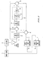
Figure 1 shows one implementation of an LED indicator device and driving circuit according to the present invention; -
Figure 2 shows a modification of the LED indicator device and driving circuit ofFigure 1 ; -
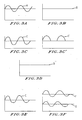
Figures 3A-3F shows a waveforms of signals generated in the LED indicator device and driving circuit ofFigures 1 and2 ; and -
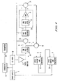
Figure 4 shows a further modification of the LED indicator device and driving circuit ofFigure 2 . - Referring now to the figures, wherein like reference numerals designate identical or corresponding parts throughout the several views, a pictorial example of an LED indicator device and LED driving circuit of the present invention as disclosed.
- The present invention is directed to an LED indicator device and a driving circuit for an LED which can provide a feedback of an luminous output of the LED to control the drive current provided to the LED.
- As shown in
Figure 1 , in the present invention apower supply 5 provides power to illuminate anLED array 10. One typical form of thepower supply 5 is a switching power supply which can employ power factor correction, current or voltage regulation, etc. Thepower supply 5 may specifically take the form of a flyback converter with power factor correction incorporated in a commercially available IC, such as the Unitrode UC2852N. TheLED array 10 may be a series or series-parallel arrangement of LEDs, and could also merely be a single LED. The present invention may find particular application as an LED traffic signal. In the context of LED traffic signals, theLED array 10 will typically be formed of parallel strings of series connected LEDs. A parallel connection of such LEDs provides redundancy in the event that one string of LEDs becomes inoperative. In a preferred embodiment thepower supply 5 is a flyback current regulator based on the Unitrode UC2852N chip which drives theLED array 10 with a DC current and a fairly large sinusoidal current ripple of twice the line frequency. This ripple is characteristic of flyback-circuit power supplies and is a necessary element. Since the average value of the sinusoidal ripple is zero, the average total current is equal to that of the DC component alone. - A
photodetector 15 is at an appropriate distance from theLED array 10 to allow it to collect light from a substantial number of LEDs within the LED array to measure the luminous output of theLED array 10. In the context of an LED array traffic signal, thephotodetector 15 may be positioned behind the lens facing theLED array 10. Thephotodetector 15 provides a feedback signal to thepower supply 5 so that thepower supply 5 can control the current provided to theLED array 10. - As noted above, the luminous output of an LED may vary with both temperature and age, and particularly may degrade with increased temperature and with increased age. To compensate for such degradation, a current supplied to the LED can be increased with increasing temperature and age. Specifically, as a temperature at an LED increases the luminous output of the LED decreases. The
photodetector 15 in this instance detects the decrease in luminous output of theLED array 10 and provides a feedback signal to thepower supply 5 which controls thepower supply 5 to increase the current supplied to theLED array 10. Thereby, theLED array 10 becomes brighter to compensate for any temperature-induced loss of luminosity. Similarly, as LEDs age they become dimmer, and thephotodetector 15 can detect any age-induced diminution of theLED array 10. In this situation thephotodetector 15 again provides a feedback signal to thepower supply 5 to increase the current supplied to theLED array 10, so that theLED array 10 becomes brighter, to thereby compensate for the age-induced diminution of theLED array 10. - In these situations it is important for the
photodetector 15 to provide an accurate indication of the luminous output of theLED array 10. This may be particularly problematic in LED array traffic signals since LED traffic signals are designed to have their LED arrays exposed outwardly by a lens, and are designed to be placed outdoors, where there is significant influence from external light sources. - Particularly, sunlight streaming in through a front lens of an LED traffic signal may be focused by the lens and projected onto the
LED array 10. A portion of such sunlight may be reflected off the surface of theLED array 10 and onto thephotodetector 15. Such reflected sunlight contributes to the output signal of thephotodetector 15. The result of this is that thephotodetector 15 does not provide an accurate indication of the luminous output of theLED array 10. The present invention has as one object to address such a situation. - To address this situation, the driving circuitry of the present invention includes conditioning circuitry between the
photodetector 15 and thepower supply 5 to ensure that the light detected by thephotodetector 15 is not influenced by external light sources in general, and particularly reflected sunlight from theLED array 10, other than the light output from theLED array 10. - Without this conditioning circuitry, the effect of sunlight reflecting off the
LED array 10 is manifested as a DC component in the signal output from thephotodetector 15. The present invention includes circuitry to reject this influence from such reflected sunlight by utilizing only the sinusoidal photodetector signal produced by the light originating from theLED array 10. That is, in the present invention, DC and low frequency components caused by stray light sources such as reflected sunlight and detected by thephotodetector 15 are rejected. - However, to maintain stable operation of the
power supply 5 when the power supply is implemented as a flyback current regulator using a power factor correction IC, it may be necessary for the intensity feedback signal to contain a DC component and a sinusoidal component in phase with the LED current waveform. - To achieve the above-noted operations, the present invention operates as follows.
- The signal detected by the
photodetector 15 is a signal such as is shown as signal A inFigure 3A . This signal A contains both the sinusoidal and DC components indicative of the LED intensity and a DC component resulting from external light sources such as reflected sunlight. The output of thephotodetector 15, i.e. signal A, is then passed through alow pass filter 20, which may have a cutoff frequency in the 10 Hz range, to separate the DC component. The signal output of thelow pass filter 20 is signal B shown inFigure 3B . Signal B thus represents the DC output ofphotodetector 15 contributed by both LED lighting and by sunlight reflecting off theLED array 10. - Next, by subtracting the DC component output from the
photodetector 15, i.e. signal B, from the original signal output fromphotodetector 15, i.e. signal A, the sinusoidal AC waveform C is produced. Signal C is then half-wave rectified byrectifier 31 and smoothed and amplified through a smoothing and amplifyingcircuit 30. This smoothing and amplifyingcircuit 30 can include a low-pass filter 32 and anamplifier 33. A waveform of the signal C' after being passed through the half-wave rectifier 31 is shown inFigure 3C '. The signal C' is then low-pass filtered and amplified as necessary to produce the DC signal D output of the smoothingcircuit 30 shown inFigure 3D . The amplitude of this DC signal D is controlled by theamplifier 33 to be proportional to the amplitude of the sinusoidal component of the original waveform signal A. - Next, the present invention synthesizes a feedback signal containing both amplitude and phase information to provide to the
power supply 5. This synthesized feedback signal is free of signals attributable from the reflected sunlight and other low frequency light sources. To achieve this operation, the original signal output of thephotodetector 15, i.e. signal A, containing a sinusoidal component indicative of LED intensity and DC components indicative of light fromLED array 10 and of stray light is summed inadder 35 with signal D, a DC output indicative of LED intensity. The output of theadder 35 is then the original signal plus a DC signal indicative of LED intensity. This output is then provided to adifference circuit 40. In thedifference circuit 40 the signal B output from thelow pass filter 20, which has a DC level with an amplitude proportional to the amplitude of the DC component of thephotodetector 15, is subtracted from the signal output ofadder 35, to thereby create a composite signal E, i.e. E=(A+C)-B. That is, the resulting signal contains only the AC and DC signals indicative of LED intensity. This composite signal E serves as a feedback signal required by thepower supply 5 to maintain a desired current in theLED array 10. More particularly, this composite signal E contains amplitude and phase information needed to maintain a stable operation of a current regulator circuit in thepower supply 5. - With the above-discussed operation in the present invention, the composite signal E is free of DC components indicative of stray light sensed by the photodetector. Moreover, the composite signal E also contains an appropriate DC component in phase with the sinusoidal signal, as is required by the
power supply 5 when thepower supply 5 is implemented as a flyback current regulator. Therefore, in the present invention an accurate intensity feedback signal can be provided to thepower supply 5 to control the illumination of theLED array 10. - One problem which may arise in the device of
Figure 1 is that an excessively high current or an excessively low current may be output from thepower supply 5 based on the composite feedback signal E. That is, if theLED array 10 is of inadequate intensity, the composite signal E may be a low value, which may result in thepower supply 5 providing too much current to theLED array 10. Conversely, if theLED array 10 exceeds intensity limits, the composite signal E may be at too high a value, and too little current may then be supplied from thepower supply 5 to theLED array 10. Providing too little current to theLED array 10 may reduce the current drawn by the signal power supply to a level insufficient to properly operate the load switch controlling the LED traffic signal. Reliable operation of theLED array 10 may become unpredictable with respect to light output if too little current is supplied to theLED array 10. When the present invention is implemented as an LED traffic signal, Triac-based load switches are often used to control traffic signals. Such Triac-based load switches may become unreliable when switching low currents, and this can result in traffic signal operational problems. - To address these concerns, a modification of the embodiment of
Figure 1 is shown inFigure 2 . This embodiment ofFigure 2 is identical to the embodiment ofFigure 1 except the embodiment ofFigure 2 includes an uppercurrent limit comparator 45 and a lowercurrent limit comparator 50. To achieve the upper and lower current limiting operations, in the present invention as shown inFigure 2 the composite feedback signal E is fed to the uppercurrent limit comparator 45. The upper current limit operation is begun by establishing a current signal G with a level equal to approximately half that of the intensity feedback signal E under normal operating conditions and 25° Celsius. This signal G is compared with the composite intensity feedback signal E such that when the level of signal G exceeds the level of the intensity feedback signal E, the signal G replaces the signal E as a feedback to thepower supply 5. This ensures that a signal of a minimum value of signal G is always supplied to thepower supply 5, and that accordingly an excessive current is not output from thepower supply 5 to theLED array 10. - A simple method of implementing the upper
current limit comparator 45 is to apply both signals E and G through a pair of wire-ORed diodes with cathodes connected to ground through a common resistor. In this configuration the larger of the two signals appears across the resistor and the other signal is blocked by its reversed-biased diode. Such a structure essentially forms an analog comparative circuit where only the larger of two analog input signals appears at the output. - The lower current limit operation is achieved by applying the output of the
upper limit comparator 45 to the lowercurrent limit comparator 50, and comparing it with a current signal F. Signal F is greater in amplitude than the intensity feedback signal E under normal conditions. In this situation, the higher amplitude LED current signal F is compared to the intensity feedback signal E, and the signal F replaces the intensity signal E to the power supply if the intensity feedback signal is greater than the signal F. This ensures that a signal with the maximum value of signal F is supplied to thepower supply 5, and that accordingly a minimum current is always provided from thepower supply 5 to theLED array 10. - A simple method of implementing the lower
current limit comparator 50 is to apply signals E and F through a pair of wire-ANDed diodes with anodes connected to a positive supply voltage through a common resistor. In this configuration, the smaller of the two signals appears at the anode connections of the two diodes while the other signal is blocked by its reversed-biased diode. This circuit again forms a type of analog comparative circuit. This time, however, only the smaller of the two analog input signals appears at the output. - A further feature of the present invention is that the use of the intensity feedback allows the incorporation of additional features which are not otherwise possible in LED indicator devices, such as LED traffic signals. With the intensity feedback operation in the present invention, and a further modification of the present invention as shown in
Figure 4 , acontroller 55 is provided to monitor the signal from thepower supply 5 to theLED array 10 indicating the current output to theLED array 10, and to receive the intensity feedback signal indicating the actual intensity of theLED array 10. By evaluating these signals, a condition of inadequate or excessive intensity of theLED array 10 may be determined when the difference between the signal output from the power supply and the intensity feedback signal exceeds a predetermined threshold. This condition may arise from long-term degradation of the LEDs, or such a condition could be a transitory condition resulting from a temporarily high temperature at theLED array 10. In either case, when such a condition arises a traffic controller circuitry or maintenance personnel can be alerted of such a condition. - In this situation, connected to the
controller 55 may be atransmitter 60 which can repeatedly transmit information as to the operation of the driving circuitry ofFigures 1 and2 .Figure 4 shows implementation of thecontroller 55 andtransmitter 60 in the circuitry ofFigure 2 , however the circuitry ofFigure 1 can also utilize thecontroller 55 andtransmitter 60. Thetransmitter 60 may be a simple infrared transmitter which sends one code to indicate a normal operation of the LED device, and which transmits a second code, or alternatively no code, to indicate that the LED device is functioning improperly, i.e., that the difference between the signal output from thepower supply 5 to theLED array 10 and the intensity feedback signal exceeds a predetermined threshold. This second code could also be sent when the uppercurrent limit comparator 45 is engaged. - It is also clearly possible to have additional codes indicating various degrees of non-compliance with any intensity requirements.
- Maintenance personnel could then be provided with receivers, for example hand-held infrared receivers, which they could point at a traffic signal including the
transmitter 60 to read the codes being transmitted. The received codes could then be decoded to provide an indication of the operation of the LED traffic signal. - Still another approach to transmitting such information could employ power line communication in the
transmitter 60. In this situation, a microprocessor in a central controller (not shown) could periodically poll a series of traffic signals by sending appropriate codes over the power lines. When a traffic signal circuit receives its identification code fromcontroller 55, it can respond by transmitting via the same power line, throughtransmitter 60, its current status with a system using the first and second codes as noted above. In one embodiment, the central controller may record in its memory instances when specific traffic signals are not meeting requirements. Alternatively, thetransmitter 60 may be equipped with a modem or radio link allowing the intensity information to be downloaded immediately to a main traffic control center. - Obviously, numerous additional modifications and variations of the present invention are possible in light of the above teachings. It is therefore to be understood that within the scope of the appended claims, the present invention may be practiced otherwise than as specifically described herein.
Claims (9)
- A driving circuit for at least one LED, comprising:(a) a power supply (5) to supply a drive current to the at least one LED (10);(b) a photodetector (15) to detect a luminous output of the at least one LED (10), and to correspondingly output a detection signal (A) wherein said detection signal includes a sinusoidal AC component (C) indicative of the luminous output of the LED and a DC component (B) indicative of the luminous output of at least one source other than said LED;
characterised in that the driving circuit further comprises:(c) a conditioning circuit to remove components of stray light from the at least one source other than said at least one LED from the detection signal (A) and to synthesize an intensity feedback signal (E) to provide the power supply (5),the conditioning circuit comprising:means (20,25,30,31) for generating a DC output (D) indicative of the luminous output of the LED based on the AC component (C) of the detection signal (A) output from the photodetector (15),means (35) for combining the detection signal (A) and the DC component (D) indicative of the luminous output of the LED, andmeans (40) for generating the intensity feedback signal (E) by subtracting the DC component (B) indicative of the luminous output of the at least one source from the signal output from the combining means (35). - The driving circuit according to claim 1, wherein said DC output generating means comprises:a first low pass filter (20) configured to extract a first substantially DC signal (B) proportional to a DC component in the detection signal (A); anda first difference circuit (25) configured to subtract the first substantially DC signal (B) from the detection signal (A) to generate the AC component (C).
- The driving circuit according to claim 2, wherein said DC output generating means further comprises:a half wave rectifier (31) to half wave rectify the sinusoidal AC component (C);a smoothing and amplifying circuit (30) to smooth and amplify the waveform from the rectifier (31) in order to generate the DC output (D) indicative of the luminous output of the LED wherein the DC output (D) is proportional to a level of the sinusoidal AC component (C) in the detection signal (A).
- The driving circuit according to claim 3, said smoothing and amplifying circuit (30) comprises a second low pass filter (32) for filtering the waveform from the rectifier (31) and an amplifier (33) to control the amplitude of the output of said low pass filter to be proportional to the level of AC component (C) in the detection signal (A).
- The driving circuit according to any preceding claim, wherein the combining means (35) is an adder circuit to add the detection signal (A) and the DC component (D) to generate an intermediate composite signal; and
the intensity feedback signal generating means (40) is a second difference circuit to subtract the first substantially DC signal (B) from the intermediate composite signal to generate the synthesized intensity feedback signal (E). - The driving circuit according to any preceding claim, wherein said conditioning circuit further comprises:vi) an upper current limit comparator (45) to ensure that the synthesized intensity feedback signal (E) has a minimum value; andvii) a lower current limit comparator (50) to ensure that the synthesized intensity feedback signal (E) does not exceed a maximum value.
- The driving circuit according to any preceding claim, further comprising:a controller (55) to compare the current supplied by the power supply (5) to the at least one LED with the synthesized intensity feedback signal (E).
- The driving circuit according to claim 6, further comprising:a transmitter (60) to transmit a signal indicating a result of the comparison executed by the controller.
- An LED indicator system comprising at least one LED and the driving circuit according to any of claims 1 to 7.
Applications Claiming Priority (2)
| Application Number | Priority Date | Filing Date | Title |
|---|---|---|---|
| US349769 | 1994-12-06 | ||
| US09/349,769 US6153985A (en) | 1999-07-09 | 1999-07-09 | LED driving circuitry with light intensity feedback to control output light intensity of an LED |
Publications (3)
| Publication Number | Publication Date |
|---|---|
| EP1067824A2 EP1067824A2 (en) | 2001-01-10 |
| EP1067824A3 EP1067824A3 (en) | 2004-01-07 |
| EP1067824B1 true EP1067824B1 (en) | 2008-03-05 |
Family
ID=23373881
Family Applications (1)
| Application Number | Title | Priority Date | Filing Date |
|---|---|---|---|
| EP00305636A Expired - Lifetime EP1067824B1 (en) | 1999-07-09 | 2000-07-04 | LED driving circuitry with light intensity feedback to control output light intensity of an LED |
Country Status (4)
| Country | Link |
|---|---|
| US (1) | US6153985A (en) |
| EP (1) | EP1067824B1 (en) |
| AT (1) | ATE388607T1 (en) |
| DE (1) | DE60038209T2 (en) |
Families Citing this family (143)
| Publication number | Priority date | Publication date | Assignee | Title |
|---|---|---|---|---|
| US6658577B2 (en) * | 1999-06-14 | 2003-12-02 | Apple Computer, Inc. | Breathing status LED indicator |
| US7049761B2 (en) | 2000-02-11 | 2006-05-23 | Altair Engineering, Inc. | Light tube and power supply circuit |
| US6426704B1 (en) * | 2000-08-17 | 2002-07-30 | Power Signal Technologies, Inc. | Modular upgradable solid state light source for traffic control |
| US6323781B1 (en) * | 2000-08-22 | 2001-11-27 | Power Signal Technologies | Electronically steerable light output viewing angles for traffic signals |
| US6614358B1 (en) * | 2000-08-29 | 2003-09-02 | Power Signal Technologies, Inc. | Solid state light with controlled light output |
| US20050099319A1 (en) * | 2000-08-29 | 2005-05-12 | Hutchison Michael C. | Traffic signal light with integral sensors |
| ATE282939T1 (en) * | 2000-08-30 | 2004-12-15 | Power Signal Technologies Inc | CONSTANT POWER LIGHT SOURCE WITH ELECTRONICALLY FILTERED OPTICAL FEEDBACK |
| CA2336497A1 (en) * | 2000-12-20 | 2002-06-20 | Daniel Chevalier | Lighting device |
| US6634779B2 (en) | 2001-01-09 | 2003-10-21 | Rpm Optoelectronics, Inc. | Method and apparatus for linear led lighting |
| US6833796B2 (en) * | 2001-01-19 | 2004-12-21 | Gelcore Llc | Count down led traffic signal |
| DE10115388A1 (en) * | 2001-03-28 | 2002-10-10 | Patent Treuhand Ges Fuer Elektrische Gluehlampen Mbh | Control circuit for an LED array |
| JP4511784B2 (en) * | 2001-12-20 | 2010-07-28 | オスラム オプト セミコンダクターズ ゲゼルシャフト ミット ベシュレンクテル ハフツング | LED array and LED module |
| WO2003067933A1 (en) * | 2002-02-08 | 2003-08-14 | Ortana Elektronik Yazilim Taahhut Sanayi Ve Ticaret Ltd. Sti. | Smart led traffic lamp |
| DE10208462A1 (en) * | 2002-02-27 | 2003-09-04 | Osram Opto Semiconductors Gmbh | lighting arrangement |
| US7057529B2 (en) * | 2002-05-24 | 2006-06-06 | Gelcore Llc | LED traffic signal load switch |
| DE10248238A1 (en) * | 2002-10-16 | 2004-04-29 | Delphi Technologies, Inc., Troy | Lighting device, in particular for motor vehicles |
| US7425798B2 (en) * | 2003-01-23 | 2008-09-16 | Lumination Llc | Intelligent light degradation sensing LED traffic signal |
| US7511436B2 (en) | 2003-05-07 | 2009-03-31 | Koninklijke Philips Electronics N.V. | Current control method and circuit for light emitting diodes |
| US6873262B2 (en) * | 2003-05-29 | 2005-03-29 | Maytag Corporation | Maintaining illumination intensity of a light emitting diode in a domestic appliance |
| US20050030192A1 (en) * | 2003-08-08 | 2005-02-10 | Weaver James T. | Power supply for LED airfield lighting |
| US6894442B1 (en) * | 2003-12-18 | 2005-05-17 | Agilent Technologies, Inc. | Luminary control system |
| GB0402974D0 (en) * | 2004-02-11 | 2004-03-17 | Bhagat Peter | Apparatus for the control of lighting and associated methods |
| EP1628494A1 (en) * | 2004-08-17 | 2006-02-22 | Dialog Semiconductor GmbH | Intelligent light source with synchronization with a digital camera |
| US8733966B2 (en) | 2004-08-20 | 2014-05-27 | Mag Instrument, Inc. | LED flashlight |
| EP1648181A1 (en) | 2004-10-12 | 2006-04-19 | Dialog Semiconductor GmbH | A multiple frame grabber |
| US20100096993A1 (en) * | 2004-11-29 | 2010-04-22 | Ian Ashdown | Integrated Modular Lighting Unit |
| US20070273290A1 (en) * | 2004-11-29 | 2007-11-29 | Ian Ashdown | Integrated Modular Light Unit |
| US7567223B2 (en) * | 2005-03-01 | 2009-07-28 | Honeywell International Inc. | Light-emitting diode (LED) hysteretic current controller |
| DE102005022832A1 (en) * | 2005-05-11 | 2006-11-16 | Arnold & Richter Cine Technik Gmbh & Co. Betriebs Kg | Headlamp for film and video recordings |
| US7675487B2 (en) * | 2005-07-15 | 2010-03-09 | Honeywell International, Inc. | Simplified light-emitting diode (LED) hysteretic current controller |
| US7986112B2 (en) | 2005-09-15 | 2011-07-26 | Mag Instrument, Inc. | Thermally self-stabilizing LED module |
| US7765792B2 (en) | 2005-10-21 | 2010-08-03 | Honeywell International Inc. | System for particulate matter sensor signal processing |
| US8123375B2 (en) * | 2005-11-18 | 2012-02-28 | Cree, Inc. | Tile for solid state lighting |
| US7872430B2 (en) | 2005-11-18 | 2011-01-18 | Cree, Inc. | Solid state lighting panels with variable voltage boost current sources |
| US8514210B2 (en) | 2005-11-18 | 2013-08-20 | Cree, Inc. | Systems and methods for calibrating solid state lighting panels using combined light output measurements |
| US7926300B2 (en) | 2005-11-18 | 2011-04-19 | Cree, Inc. | Adaptive adjustment of light output of solid state lighting panels |
| JP5249773B2 (en) * | 2005-11-18 | 2013-07-31 | クリー インコーポレイテッド | Solid state lighting panel with variable voltage boost current source |
| DE102005062020A1 (en) * | 2005-12-22 | 2007-01-25 | Daimlerchrysler Ag | Head lights, rear lights, or fog lights of vehicle, comprise integrated sensor for function check |
| US8441210B2 (en) * | 2006-01-20 | 2013-05-14 | Point Somee Limited Liability Company | Adaptive current regulation for solid state lighting |
| US8558470B2 (en) * | 2006-01-20 | 2013-10-15 | Point Somee Limited Liability Company | Adaptive current regulation for solid state lighting |
| JP2009538536A (en) | 2006-05-26 | 2009-11-05 | クリー エル イー ディー ライティング ソリューションズ インコーポレイテッド | Solid state light emitting device and method of manufacturing the same |
| EP2035745B1 (en) * | 2006-05-31 | 2020-04-29 | IDEAL Industries Lighting LLC | Lighting device with color control, and method of lighting |
| EP2573923B1 (en) * | 2006-09-13 | 2019-04-03 | Cree, Inc. | Circuit for supplying electrical power |
| KR100787221B1 (en) * | 2006-09-26 | 2007-12-21 | 삼성전자주식회사 | LED-based optical system and its aging compensation method |
| KR20090082378A (en) | 2006-10-05 | 2009-07-30 | 코닌클리즈케 필립스 일렉트로닉스 엔.브이. | Optical module package |
| BRPI0718153A2 (en) | 2006-10-27 | 2013-11-05 | Koninkl Philips Electronics Nv | Controlled Color Light Source and Method for Controlling Color Generation in a Light Source |
| US8111011B1 (en) | 2007-01-11 | 2012-02-07 | Leotek Electronics Corporation | LED luminaire with improved life and operation management |
| WO2008091837A2 (en) * | 2007-01-22 | 2008-07-31 | Cree Led Lighting Solutions, Inc. | Fault tolerant light emitters, systems incorporating fault tolerant light emitters and methods of fabricating fault tolerant light emitters |
| TWI440210B (en) | 2007-01-22 | 2014-06-01 | 克里公司 | Illumination device using external interconnection array of light-emitting device and manufacturing method thereof |
| US8456388B2 (en) * | 2007-02-14 | 2013-06-04 | Cree, Inc. | Systems and methods for split processor control in a solid state lighting panel |
| WO2008104228A1 (en) * | 2007-03-01 | 2008-09-04 | Patent-Treuhand-Gesellschaft für elektrische Glühlampen mbH | Circuit arrangement and method for controlling semiconductor light sources |
| US7652480B2 (en) * | 2007-04-26 | 2010-01-26 | General Electric Company | Methods and systems for testing a functional status of a light unit |
| EP2469152B1 (en) | 2007-05-08 | 2018-11-28 | Cree, Inc. | Lighting devices and methods for lighting |
| US8049709B2 (en) | 2007-05-08 | 2011-11-01 | Cree, Inc. | Systems and methods for controlling a solid state lighting panel |
| US7712917B2 (en) * | 2007-05-21 | 2010-05-11 | Cree, Inc. | Solid state lighting panels with limited color gamut and methods of limiting color gamut in solid state lighting panels |
| US20090033612A1 (en) * | 2007-07-31 | 2009-02-05 | Roberts John K | Correction of temperature induced color drift in solid state lighting displays |
| US8829820B2 (en) * | 2007-08-10 | 2014-09-09 | Cree, Inc. | Systems and methods for protecting display components from adverse operating conditions |
| US8866410B2 (en) * | 2007-11-28 | 2014-10-21 | Cree, Inc. | Solid state lighting devices and methods of manufacturing the same |
| US8823630B2 (en) * | 2007-12-18 | 2014-09-02 | Cree, Inc. | Systems and methods for providing color management control in a lighting panel |
| JP5108490B2 (en) * | 2007-12-19 | 2012-12-26 | オリンパス株式会社 | Lighting device for cell analyzer |
| US8118447B2 (en) | 2007-12-20 | 2012-02-21 | Altair Engineering, Inc. | LED lighting apparatus with swivel connection |
| US7888883B2 (en) * | 2008-01-25 | 2011-02-15 | Eveready Battery Company, Inc. | Lighting device having cross-fade and method thereof |
| EP2283701B1 (en) * | 2008-05-13 | 2013-05-29 | Nxp B.V. | Method and circuit arrangement for cycle-by-cycle control of a led current flowing through a led circuit arrangement, and associated circuit composition and lighting system |
| US8125163B2 (en) | 2008-05-21 | 2012-02-28 | Manufacturing Resources International, Inc. | Backlight adjustment system |
| US8988011B2 (en) * | 2008-05-21 | 2015-03-24 | Manufacturing Resources International, Inc. | System and method for managing backlight luminance variations |
| US8360599B2 (en) | 2008-05-23 | 2013-01-29 | Ilumisys, Inc. | Electric shock resistant L.E.D. based light |
| US20100007588A1 (en) * | 2008-07-09 | 2010-01-14 | Adaptive Micro Systems Llc | System and method for led degradation and temperature compensation |
| US8344638B2 (en) | 2008-07-29 | 2013-01-01 | Point Somee Limited Liability Company | Apparatus, system and method for cascaded power conversion |
| US9022612B2 (en) * | 2008-08-07 | 2015-05-05 | Mag Instrument, Inc. | LED module |
| US7938562B2 (en) | 2008-10-24 | 2011-05-10 | Altair Engineering, Inc. | Lighting including integral communication apparatus |
| US8214084B2 (en) | 2008-10-24 | 2012-07-03 | Ilumisys, Inc. | Integration of LED lighting with building controls |
| US8901823B2 (en) | 2008-10-24 | 2014-12-02 | Ilumisys, Inc. | Light and light sensor |
| US8324817B2 (en) | 2008-10-24 | 2012-12-04 | Ilumisys, Inc. | Light and light sensor |
| US8653984B2 (en) | 2008-10-24 | 2014-02-18 | Ilumisys, Inc. | Integration of LED lighting control with emergency notification systems |
| US8444292B2 (en) | 2008-10-24 | 2013-05-21 | Ilumisys, Inc. | End cap substitute for LED-based tube replacement light |
| US8310172B2 (en) * | 2008-12-10 | 2012-11-13 | Linear Technology Corporation | Current ripple reduction circuit for LEDs |
| US8089216B2 (en) * | 2008-12-10 | 2012-01-03 | Linear Technology Corporation | Linearity in LED dimmer control |
| US8692481B2 (en) * | 2008-12-10 | 2014-04-08 | Linear Technology Corporation | Dimmer-controlled LEDs using flyback converter with high power factor |
| US9326346B2 (en) | 2009-01-13 | 2016-04-26 | Terralux, Inc. | Method and device for remote sensing and control of LED lights |
| US8358085B2 (en) | 2009-01-13 | 2013-01-22 | Terralux, Inc. | Method and device for remote sensing and control of LED lights |
| US8556452B2 (en) | 2009-01-15 | 2013-10-15 | Ilumisys, Inc. | LED lens |
| US9247598B2 (en) | 2009-01-16 | 2016-01-26 | Mag Instrument, Inc. | Portable lighting devices |
| US8664880B2 (en) | 2009-01-21 | 2014-03-04 | Ilumisys, Inc. | Ballast/line detection circuit for fluorescent replacement lamps |
| US8174197B2 (en) * | 2009-04-09 | 2012-05-08 | Ge Lighting Solutions Llc | Power control circuit and method |
| US8330381B2 (en) | 2009-05-14 | 2012-12-11 | Ilumisys, Inc. | Electronic circuit for DC conversion of fluorescent lighting ballast |
| US8299695B2 (en) | 2009-06-02 | 2012-10-30 | Ilumisys, Inc. | Screw-in LED bulb comprising a base having outwardly projecting nodes |
| US8502476B2 (en) * | 2009-10-16 | 2013-08-06 | Samsung Electronics Co., Ltd | Method and apparatus for controlling power consumption of light source in mobile projector |
| CN104254178A (en) | 2009-11-17 | 2014-12-31 | 特锐拉克斯有限公司 | Led power-supply detection and control |
| CN102695558B (en) * | 2009-12-02 | 2014-04-16 | 松下神视株式会社 | UV-irradiation apparatus |
| WO2011084525A1 (en) | 2009-12-16 | 2011-07-14 | Exclara, Inc. | Adaptive current regulation for solid state lighting |
| EP2553320A4 (en) | 2010-03-26 | 2014-06-18 | Ilumisys Inc | LED LAMP COMPRISING A THERMOELECTRIC GENERATOR |
| EP2553332B1 (en) | 2010-03-26 | 2016-03-23 | iLumisys, Inc. | Inside-out led bulb |
| US9057493B2 (en) | 2010-03-26 | 2015-06-16 | Ilumisys, Inc. | LED light tube with dual sided light distribution |
| US8371059B1 (en) * | 2010-06-30 | 2013-02-12 | The United States Of America As Represented By The Secretary Of The Army | Aiming post light |
| US8454193B2 (en) | 2010-07-08 | 2013-06-04 | Ilumisys, Inc. | Independent modules for LED fluorescent light tube replacement |
| US8596813B2 (en) | 2010-07-12 | 2013-12-03 | Ilumisys, Inc. | Circuit board mount for LED light tube |
| US8258709B2 (en) | 2010-09-01 | 2012-09-04 | Osram Sylvania Inc. | LED control using modulation frequency detection techniques |
| US8390205B2 (en) | 2010-09-01 | 2013-03-05 | Osram Sylvania Inc. | LED control using modulation frequency detection techniques |
| US9596738B2 (en) | 2010-09-16 | 2017-03-14 | Terralux, Inc. | Communication with lighting units over a power bus |
| AU2011301977B2 (en) | 2010-09-16 | 2014-05-22 | Terralux, Inc. | Communication with lighting units over a power bus |
| EP2633227B1 (en) | 2010-10-29 | 2018-08-29 | iLumisys, Inc. | Mechanisms for reducing risk of shock during installation of light tube |
| US8870415B2 (en) | 2010-12-09 | 2014-10-28 | Ilumisys, Inc. | LED fluorescent tube replacement light with reduced shock hazard |
| US8803704B2 (en) | 2011-03-21 | 2014-08-12 | GE Lighting Solutions, LLC | Traffic signal loading platform |
| US8723427B2 (en) | 2011-04-05 | 2014-05-13 | Abl Ip Holding Llc | Systems and methods for LED control using on-board intelligence |
| JP5615226B2 (en) * | 2011-05-11 | 2014-10-29 | キヤノン株式会社 | LIGHT CONTROL DEVICE, ITS CONTROL METHOD, AND DISPLAY DEVICE |
| DE102011107089B4 (en) | 2011-07-11 | 2013-06-06 | Austriamicrosystems Ag | Power supply arrangement and method for supplying power to an electrical load |
| US9072171B2 (en) | 2011-08-24 | 2015-06-30 | Ilumisys, Inc. | Circuit board mount for LED light |
| KR102047433B1 (en) | 2011-09-23 | 2019-12-04 | 매뉴팩처링 리소시스 인터내셔널 인코포레이티드 | System and method for environmental adaptation of display characteristics |
| US9657930B2 (en) | 2011-12-13 | 2017-05-23 | Ephesus Lighting, Inc. | High intensity light-emitting diode luminaire assembly |
| US8896231B2 (en) | 2011-12-16 | 2014-11-25 | Terralux, Inc. | Systems and methods of applying bleed circuits in LED lamps |
| US9184518B2 (en) | 2012-03-02 | 2015-11-10 | Ilumisys, Inc. | Electrical connector header for an LED-based light |
| US8729815B2 (en) | 2012-03-12 | 2014-05-20 | Osram Sylvania Inc. | Current control system |
| WO2014008463A1 (en) | 2012-07-06 | 2014-01-09 | Ilumisys, Inc. | Power supply assembly for led-based light tube |
| US9271367B2 (en) | 2012-07-09 | 2016-02-23 | Ilumisys, Inc. | System and method for controlling operation of an LED-based light |
| US9285084B2 (en) | 2013-03-14 | 2016-03-15 | Ilumisys, Inc. | Diffusers for LED-based lights |
| US9265119B2 (en) | 2013-06-17 | 2016-02-16 | Terralux, Inc. | Systems and methods for providing thermal fold-back to LED lights |
| US9578728B2 (en) * | 2013-06-18 | 2017-02-21 | Dialight Corporation | Long life, fail safe traffic light |
| US9267650B2 (en) | 2013-10-09 | 2016-02-23 | Ilumisys, Inc. | Lens for an LED-based light |
| US9574717B2 (en) | 2014-01-22 | 2017-02-21 | Ilumisys, Inc. | LED-based light with addressed LEDs |
| US9510400B2 (en) | 2014-05-13 | 2016-11-29 | Ilumisys, Inc. | User input systems for an LED-based light |
| US9520742B2 (en) | 2014-07-03 | 2016-12-13 | Hubbell Incorporated | Monitoring system and method |
| US10319408B2 (en) | 2015-03-30 | 2019-06-11 | Manufacturing Resources International, Inc. | Monolithic display with separately controllable sections |
| US10593255B2 (en) | 2015-05-14 | 2020-03-17 | Manufacturing Resources International, Inc. | Electronic display with environmental adaptation of display characteristics based on location |
| US10321549B2 (en) | 2015-05-14 | 2019-06-11 | Manufacturing Resources International, Inc. | Display brightness control based on location data |
| US10607520B2 (en) | 2015-05-14 | 2020-03-31 | Manufacturing Resources International, Inc. | Method for environmental adaptation of display characteristics based on location |
| US10922736B2 (en) | 2015-05-15 | 2021-02-16 | Manufacturing Resources International, Inc. | Smart electronic display for restaurants |
| US10161568B2 (en) | 2015-06-01 | 2018-12-25 | Ilumisys, Inc. | LED-based light with canted outer walls |
| US10269156B2 (en) | 2015-06-05 | 2019-04-23 | Manufacturing Resources International, Inc. | System and method for blending order confirmation over menu board background |
| US10161619B2 (en) | 2015-12-28 | 2018-12-25 | Eaton Intelligent Power Limited | LED illumination device with vent to heat sink |
| WO2017117009A1 (en) | 2015-12-28 | 2017-07-06 | Ephesus Lighting, Inc. | Led illumination device with single pressure cavity |
| US10319271B2 (en) | 2016-03-22 | 2019-06-11 | Manufacturing Resources International, Inc. | Cyclic redundancy check for electronic displays |
| EP3465613A4 (en) | 2016-05-31 | 2019-10-23 | Manufacturing Resources International, Inc. | METHOD AND SYSTEM FOR REMOTE IMAGE VERIFICATION ON ELECTRONIC DISPLAY UNIT |
| WO2018009917A1 (en) | 2016-07-08 | 2018-01-11 | Manufacturing Resources International, Inc. | Controlling display brightness based on image capture device data |
| WO2018031717A2 (en) | 2016-08-10 | 2018-02-15 | Manufacturing Resources International, Inc. | Dynamic dimming led backlight for lcd array |
| US10386052B2 (en) * | 2018-01-08 | 2019-08-20 | Tridonic Gmbh & Co Kg | Method of identifying a malfunction in a laser-driven remote phosphor luminaire |
| US10578658B2 (en) | 2018-05-07 | 2020-03-03 | Manufacturing Resources International, Inc. | System and method for measuring power consumption of an electronic display assembly |
| US10782276B2 (en) | 2018-06-14 | 2020-09-22 | Manufacturing Resources International, Inc. | System and method for detecting gas recirculation or airway occlusion |
| US11526044B2 (en) | 2020-03-27 | 2022-12-13 | Manufacturing Resources International, Inc. | Display unit with orientation based operation |
| US12105370B2 (en) | 2021-03-15 | 2024-10-01 | Manufacturing Resources International, Inc. | Fan control for electronic display assemblies |
| US12022635B2 (en) | 2021-03-15 | 2024-06-25 | Manufacturing Resources International, Inc. | Fan control for electronic display assemblies |
| US11895362B2 (en) | 2021-10-29 | 2024-02-06 | Manufacturing Resources International, Inc. | Proof of play for images displayed at electronic displays |
| US12027132B1 (en) | 2023-06-27 | 2024-07-02 | Manufacturing Resources International, Inc. | Display units with automated power governing |
| US20250242750A1 (en) * | 2024-01-28 | 2025-07-31 | Ross Blankenship100 | Vehicular backup safety system |
Family Cites Families (5)
| Publication number | Priority date | Publication date | Assignee | Title |
|---|---|---|---|---|
| GB2287533B (en) * | 1994-03-08 | 1998-09-16 | Hitachi Maxell | Fluorescent detecting apparatus and method |
| DE4428423A1 (en) * | 1994-08-11 | 1996-02-15 | Diehl Gmbh & Co | Measurement method for measuring flicker intensity of discharge lamp |
| DE19606674B4 (en) * | 1996-02-22 | 2004-05-13 | Siemens Ag | Procedure for controlling the lighting of a room |
| US5783909A (en) * | 1997-01-10 | 1998-07-21 | Relume Corporation | Maintaining LED luminous intensity |
| WO1998052182A1 (en) * | 1997-05-14 | 1998-11-19 | Unisplay S.A. | Display system with brightness correction |
-
1999
- 1999-07-09 US US09/349,769 patent/US6153985A/en not_active Expired - Lifetime
-
2000
- 2000-07-04 EP EP00305636A patent/EP1067824B1/en not_active Expired - Lifetime
- 2000-07-04 AT AT00305636T patent/ATE388607T1/en not_active IP Right Cessation
- 2000-07-04 DE DE60038209T patent/DE60038209T2/en not_active Expired - Lifetime
Non-Patent Citations (1)
| Title |
|---|
| None * |
Also Published As
| Publication number | Publication date |
|---|---|
| ATE388607T1 (en) | 2008-03-15 |
| EP1067824A2 (en) | 2001-01-10 |
| DE60038209D1 (en) | 2008-04-17 |
| DE60038209T2 (en) | 2009-03-12 |
| EP1067824A3 (en) | 2004-01-07 |
| US6153985A (en) | 2000-11-28 |
Similar Documents
| Publication | Publication Date | Title |
|---|---|---|
| US6153985A (en) | LED driving circuitry with light intensity feedback to control output light intensity of an LED | |
| US5959448A (en) | Optically isolated line voltage sensing circuit | |
| EP0116435B1 (en) | White balance control system | |
| US20150305119A1 (en) | Lighting control device and lighting system | |
| JP2013223389A (en) | Power supply system | |
| US9538592B2 (en) | LED lighting system | |
| US6642502B2 (en) | Light-transmitting object identifying apparatus and method | |
| JP2000184718A (en) | Switching power supply | |
| US20080128587A1 (en) | Apparatus and method for controlling optical power and extinction ratio | |
| US20090243799A1 (en) | Communication system for inductive power transfer system | |
| JPH0814501B2 (en) | Optical power supply type signal processor | |
| CA2237779A1 (en) | Meter testing circuit | |
| US4851660A (en) | Photoelectric compressed analog signal strength indicator | |
| JP2005285527A (en) | LED signal lamp | |
| KR20150059019A (en) | Driving apparatus for light emitting diode | |
| KR20040084004A (en) | Apparatus for driving light emitting diode for signal lamp | |
| US6094143A (en) | Light obstruction type smoke sensor | |
| CN117121639A (en) | Circuit system and method for determining utility voltage in isolating switch driver equipment | |
| KR200224410Y1 (en) | Error detector of lighting system using power line | |
| JP3033686B2 (en) | Optical sensor device | |
| JP3186669B2 (en) | Identification device | |
| US6396060B1 (en) | System for detecting radiation in the presence of more intense background radiation | |
| JPH07111759B2 (en) | Light energy driven detector | |
| US8525426B2 (en) | Lighting apparatus and controlling method thereof | |
| EP0339334A2 (en) | Optically coupled remote sensor apparatus and system |
Legal Events
| Date | Code | Title | Description |
|---|---|---|---|
| PUAI | Public reference made under article 153(3) epc to a published international application that has entered the european phase |
Free format text: ORIGINAL CODE: 0009012 |
|
| AK | Designated contracting states |
Kind code of ref document: A2 Designated state(s): AT BE CH CY DE DK ES FI FR GB GR IE IT LI LU MC NL PT SE |
|
| AX | Request for extension of the european patent |
Free format text: AL;LT;LV;MK;RO;SI |
|
| 17P | Request for examination filed |
Effective date: 20010718 |
|
| PUAL | Search report despatched |
Free format text: ORIGINAL CODE: 0009013 |
|
| AK | Designated contracting states |
Kind code of ref document: A3 Designated state(s): AT BE CH CY DE DK ES FI FR GB GR IE IT LI LU MC NL PT SE |
|
| AX | Request for extension of the european patent |
Extension state: AL LT LV MK RO SI |
|
| RIC1 | Information provided on ipc code assigned before grant |
Ipc: 7G 01J 1/32 B Ipc: 7H 05B 33/08 A |
|
| AKX | Designation fees paid |
Designated state(s): AT BE CH CY DE DK ES FI FR GB GR IE IT LI LU MC NL PT SE |
|
| 17Q | First examination report despatched |
Effective date: 20051221 |
|
| GRAP | Despatch of communication of intention to grant a patent |
Free format text: ORIGINAL CODE: EPIDOSNIGR1 |
|
| GRAS | Grant fee paid |
Free format text: ORIGINAL CODE: EPIDOSNIGR3 |
|
| GRAA | (expected) grant |
Free format text: ORIGINAL CODE: 0009210 |
|
| AK | Designated contracting states |
Kind code of ref document: B1 Designated state(s): AT BE CH CY DE DK ES FI FR GB GR IE IT LI LU MC NL PT SE |
|
| REG | Reference to a national code |
Ref country code: GB Ref legal event code: FG4D |
|
| REG | Reference to a national code |
Ref country code: CH Ref legal event code: EP |
|
| REG | Reference to a national code |
Ref country code: IE Ref legal event code: FG4D |
|
| REF | Corresponds to: |
Ref document number: 60038209 Country of ref document: DE Date of ref document: 20080417 Kind code of ref document: P |
|
| PG25 | Lapsed in a contracting state [announced via postgrant information from national office to epo] |
Ref country code: FI Free format text: LAPSE BECAUSE OF FAILURE TO SUBMIT A TRANSLATION OF THE DESCRIPTION OR TO PAY THE FEE WITHIN THE PRESCRIBED TIME-LIMIT Effective date: 20080305 Ref country code: ES Free format text: LAPSE BECAUSE OF FAILURE TO SUBMIT A TRANSLATION OF THE DESCRIPTION OR TO PAY THE FEE WITHIN THE PRESCRIBED TIME-LIMIT Effective date: 20080616 |
|
| PG25 | Lapsed in a contracting state [announced via postgrant information from national office to epo] |
Ref country code: AT Free format text: LAPSE BECAUSE OF FAILURE TO SUBMIT A TRANSLATION OF THE DESCRIPTION OR TO PAY THE FEE WITHIN THE PRESCRIBED TIME-LIMIT Effective date: 20080305 |
|
| NLV1 | Nl: lapsed or annulled due to failure to fulfill the requirements of art. 29p and 29m of the patents act | ||
| PG25 | Lapsed in a contracting state [announced via postgrant information from national office to epo] |
Ref country code: BE Free format text: LAPSE BECAUSE OF FAILURE TO SUBMIT A TRANSLATION OF THE DESCRIPTION OR TO PAY THE FEE WITHIN THE PRESCRIBED TIME-LIMIT Effective date: 20080305 |
|
| ET | Fr: translation filed | ||
| PG25 | Lapsed in a contracting state [announced via postgrant information from national office to epo] |
Ref country code: SE Free format text: LAPSE BECAUSE OF FAILURE TO SUBMIT A TRANSLATION OF THE DESCRIPTION OR TO PAY THE FEE WITHIN THE PRESCRIBED TIME-LIMIT Effective date: 20080605 Ref country code: NL Free format text: LAPSE BECAUSE OF FAILURE TO SUBMIT A TRANSLATION OF THE DESCRIPTION OR TO PAY THE FEE WITHIN THE PRESCRIBED TIME-LIMIT Effective date: 20080305 Ref country code: PT Free format text: LAPSE BECAUSE OF FAILURE TO SUBMIT A TRANSLATION OF THE DESCRIPTION OR TO PAY THE FEE WITHIN THE PRESCRIBED TIME-LIMIT Effective date: 20080805 |
|
| PLBE | No opposition filed within time limit |
Free format text: ORIGINAL CODE: 0009261 |
|
| STAA | Information on the status of an ep patent application or granted ep patent |
Free format text: STATUS: NO OPPOSITION FILED WITHIN TIME LIMIT |
|
| PG25 | Lapsed in a contracting state [announced via postgrant information from national office to epo] |
Ref country code: DK Free format text: LAPSE BECAUSE OF FAILURE TO SUBMIT A TRANSLATION OF THE DESCRIPTION OR TO PAY THE FEE WITHIN THE PRESCRIBED TIME-LIMIT Effective date: 20080305 |
|
| 26N | No opposition filed |
Effective date: 20081208 |
|
| REG | Reference to a national code |
Ref country code: CH Ref legal event code: PL |
|
| PG25 | Lapsed in a contracting state [announced via postgrant information from national office to epo] |
Ref country code: MC Free format text: LAPSE BECAUSE OF NON-PAYMENT OF DUE FEES Effective date: 20080731 |
|
| PG25 | Lapsed in a contracting state [announced via postgrant information from national office to epo] |
Ref country code: CH Free format text: LAPSE BECAUSE OF NON-PAYMENT OF DUE FEES Effective date: 20080731 Ref country code: LI Free format text: LAPSE BECAUSE OF NON-PAYMENT OF DUE FEES Effective date: 20080731 |
|
| PG25 | Lapsed in a contracting state [announced via postgrant information from national office to epo] |
Ref country code: IE Free format text: LAPSE BECAUSE OF NON-PAYMENT OF DUE FEES Effective date: 20080704 |
|
| PG25 | Lapsed in a contracting state [announced via postgrant information from national office to epo] |
Ref country code: IT Free format text: LAPSE BECAUSE OF FAILURE TO SUBMIT A TRANSLATION OF THE DESCRIPTION OR TO PAY THE FEE WITHIN THE PRESCRIBED TIME-LIMIT Effective date: 20080305 |
|
| PG25 | Lapsed in a contracting state [announced via postgrant information from national office to epo] |
Ref country code: CY Free format text: LAPSE BECAUSE OF FAILURE TO SUBMIT A TRANSLATION OF THE DESCRIPTION OR TO PAY THE FEE WITHIN THE PRESCRIBED TIME-LIMIT Effective date: 20080305 |
|
| PG25 | Lapsed in a contracting state [announced via postgrant information from national office to epo] |
Ref country code: LU Free format text: LAPSE BECAUSE OF NON-PAYMENT OF DUE FEES Effective date: 20080704 |
|
| PG25 | Lapsed in a contracting state [announced via postgrant information from national office to epo] |
Ref country code: GR Free format text: LAPSE BECAUSE OF FAILURE TO SUBMIT A TRANSLATION OF THE DESCRIPTION OR TO PAY THE FEE WITHIN THE PRESCRIBED TIME-LIMIT Effective date: 20080606 |
|
| REG | Reference to a national code |
Ref country code: FR Ref legal event code: PLFP Year of fee payment: 17 |
|
| REG | Reference to a national code |
Ref country code: FR Ref legal event code: PLFP Year of fee payment: 18 |
|
| REG | Reference to a national code |
Ref country code: FR Ref legal event code: PLFP Year of fee payment: 19 |
|
| PGFP | Annual fee paid to national office [announced via postgrant information from national office to epo] |
Ref country code: FR Payment date: 20190621 Year of fee payment: 20 |
|
| PGFP | Annual fee paid to national office [announced via postgrant information from national office to epo] |
Ref country code: DE Payment date: 20190617 Year of fee payment: 20 Ref country code: GB Payment date: 20190626 Year of fee payment: 20 |
|
| REG | Reference to a national code |
Ref country code: DE Ref legal event code: R079 Ref document number: 60038209 Country of ref document: DE Free format text: PREVIOUS MAIN CLASS: H05B0033080000 Ipc: H05B0045000000 |
|
| REG | Reference to a national code |
Ref country code: DE Ref legal event code: R071 Ref document number: 60038209 Country of ref document: DE |
|
| REG | Reference to a national code |
Ref country code: GB Ref legal event code: PE20 Expiry date: 20200703 |
|
| PG25 | Lapsed in a contracting state [announced via postgrant information from national office to epo] |
Ref country code: GB Free format text: LAPSE BECAUSE OF EXPIRATION OF PROTECTION Effective date: 20200703 |