EP1067810A2 - Packet transfer method and system - Google Patents
Packet transfer method and system Download PDFInfo
- Publication number
- EP1067810A2 EP1067810A2 EP00114298A EP00114298A EP1067810A2 EP 1067810 A2 EP1067810 A2 EP 1067810A2 EP 00114298 A EP00114298 A EP 00114298A EP 00114298 A EP00114298 A EP 00114298A EP 1067810 A2 EP1067810 A2 EP 1067810A2
- Authority
- EP
- European Patent Office
- Prior art keywords
- data
- terminal
- dedicated channel
- channel
- base station
- Prior art date
- Legal status (The legal status is an assumption and is not a legal conclusion. Google has not performed a legal analysis and makes no representation as to the accuracy of the status listed.)
- Withdrawn
Links
Images






Classifications
-
- H—ELECTRICITY
- H04—ELECTRIC COMMUNICATION TECHNIQUE
- H04B—TRANSMISSION
- H04B7/00—Radio transmission systems, i.e. using radiation field
- H04B7/24—Radio transmission systems, i.e. using radiation field for communication between two or more posts
- H04B7/26—Radio transmission systems, i.e. using radiation field for communication between two or more posts at least one of which is mobile
-
- H—ELECTRICITY
- H04—ELECTRIC COMMUNICATION TECHNIQUE
- H04W—WIRELESS COMMUNICATION NETWORKS
- H04W4/00—Services specially adapted for wireless communication networks; Facilities therefor
- H04W4/18—Information format or content conversion, e.g. adaptation by the network of the transmitted or received information for the purpose of wireless delivery to users or terminals
-
- H—ELECTRICITY
- H04—ELECTRIC COMMUNICATION TECHNIQUE
- H04W—WIRELESS COMMUNICATION NETWORKS
- H04W92/00—Interfaces specially adapted for wireless communication networks
- H04W92/04—Interfaces between hierarchically different network devices
- H04W92/12—Interfaces between hierarchically different network devices between access points and access point controllers
Definitions
- the present invention relates to a packet transfer method and system. More particularly, it relates to a system and method for controlling packet data transfer in mobile data communication.
- the mobile communication system includes a plurality of terminals 110a-110c, a base station 120 connected to the terminals 110a-110c via wireless lines, and a switching center 130 linked to the base station 120 via wire lines.
- the switching center 130 is connected to a network 140, which is one type of a public network of PSTN (Plain Service Telephone Network).
- PSTN Public Service Telephone Network
- Each of the terminals 110a-110c includes an information terminal unit and a mobile unit such as a PHS or cell phone terminal linked to the information terminal unit.
- the wire line for interconnecting the base station 120 and the switching center 130 includes a shared channel and a dedicated channel.
- the shared channel can be shared by the multiple terminals, while the dedicated channel can exclusively be used by one of the terminals.
- the dedicated channel is allocated to the terminal, thereby allowing the data transferred from the terminal to be transferred through the dedicated channel.
- an object of the present invention is to provide a packet transfer method and system adapted to minimize delay in data and discard of data in the mobile communication system, and thus to provide improvements in processing ability and service quality in the base station and the switching center.
- a data transfer method in a mobile data communication system including a mobile terminal, a base station communicated to the mobile terminal by wireless, and a switching center connected to the base station via a wire line, comprising that, when a quantity of data residing in a dedicated channel of the wire line between the base station and the switching center exceeds a predetermined value, the dedicated channel being exclusively allocated to the mobile terminal, then a further dedicated channel is allocated to the mobile terminal, thereby transmitting the data through the multiple dedicated channels.
- a data transfer method in a mobile data communication system including a mobile terminal, a base station communicated to the mobile terminal by wireless, and a switching center connected to the base station via a wire line, comprising that, when a quantity of data residing in a dedicated channel of the wire line between the base station and the switching center exceeds a predetermined value, the dedicated channel being exclusively allocated to the mobile terminal, then a shared channel to be shared by the multiple mobile terminals is applied to the mobile terminal, thereby transmitting the data through the shared channel and the dedicated channel.
- a communication system embodying the present invention includes a plurality of terminals, a base station connected to the terminals via wireless lines, and a switching center linked to the base station via a plurality of wire lines.
- the wire line includes a shared channel and a dedicated channel in which the shared channel can be shared by the terminals, while the dedicated channel can be used by only one of the terminals.
- a packet transfer method in the communication system permits data transferred from the terminal to be transferred by packets in which the data are separated by a certain length.
- the packet transfer method allocates the dedicated channel to the terminal, thereby permitting the data transferred from the terminal to be transferred through the dedicated channel.
- the packet transfer method in data transfer through the dedicated channel that is allocated to the terminal, when data transferred from the terminal is waited because of an excessive quantity of such transferred data, and further when a queuing data quantity of the data is equal to or greater than a predetermined delay data quantity-generating value, then another dedicated channel (hereinafter called an "additional dedicated channel") is allocated to the terminal, thereby transferring the data through the dedicated channel and the additional dedicated channel until the queuing data quantity is equal to or less than a predetermined delay data quantity-restoring value.
- an additional dedicated channel another dedicated channel
- Processing to allocate the additional dedicated channel includes the following steps:
- the base station determines whether a queuing data quantity of data transferred from the terminal is equal to or greater than a delay data quantity-generating value. When the determination results in "YES", then the base station requests the switching center through the shared channel to allocate the additional dedicated channel to the terminal.
- the switching center determines upon receipt of such a request from the base station whether the additional dedicated channel can be allocated to the terminal. Then, the switching center delivers the result of the determination to the base station through the shared channel.
- the base station allocates the additional dedicated channel to the terminal upon receipt of the positive result of the determination from the switching center.
- Processing to release the additional dedicated channel includes the following steps:
- the base station determines whether a queuing data quantity of data transferred from the terminal is equal to or less than a delay data quantity-restoring value. When the determination results in "YES", then the base station requests the switching center through the shared channel to free the additional dedicated channel from the terminal.
- the switching center determines upon receipt of such a request from the base station whether the additional dedicated channel already allocated to the terminal can be released therefrom. Then, the switching center conveys the result of the determination to the base station.
- the base station releases the additional dedicated channel from the terminal upon receipt of the positive result of the determination from the switching center.
- the dedicated channel allocated to the terminal when data transferred from the terminal is waited because of an excessive quantity of transferred data, and further when a queuing data quantity of the data is equal to or greater than a predetermined delay data quantity-generating value, then another dedicated channel (or an "additional dedicated channel") is allocated to the terminal, thereby transferring the data through the additional dedicated channel until the queuing data quantity is equal to or less than a predetermined delay data quantity-restoring value.
- Processing to allocate the additional dedicated channel includes the following steps:
- the switching center determines whether a queuing data quantity of data transferred to the terminal is equal to or greater than a delay data quantity-generating value. When the determination results in "YES", then the switching center requests the base station through the shared channel to allocate the additional dedicated channel to the terminal.
- the base station determines upon receipt of such a request from the switching center whether the additional dedicated channel can be allocated to the terminal. Then, the base station delivers the result of the determination to the switching center through the shared channel.
- the switching center allocates the additional dedicated channel to the terminal upon receipt of the positive result of the determination from the base station.
- Processing to release the additional dedicated channel includes the following steps:
- the switching center determines whether a queuing data quantity of data transferred to the terminal is equal to or less than a delay data quantity-restoring value. When the determination results in "YES", then the switching center requests the base station to release the additional dedicated channel to the terminal.
- the base station determines upon receipt of such a request from the switching center whether the additional dedicated channel already allocated to the terminal can be released from the terminal. Then, the base station conveys the result of the determination to the switching center.
- the switching center releases the additional dedicated channel from the terminal upon receipt of the positive result of the determination from the base station.
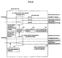
- the base station includes a measurement means 103, a mode-switching means 101, a control means 102, a rearrangement means 104, a multi-receiving control means 105, and a multi-receiving release means 106.
- the measurement means 103 permits a queuing data quantity of data transferred from the terminal to be counted for each dedicated channel, which queuing data quantity resides in a buffer.
- the mode-switching means 101 switches between a single channel mode and a multi-channel mode.
- the single channel mode permits the dedicated channel to be applied to the terminal.
- the multi-channel mode permits the dedicated channel and the additional dedicated channel to be applied together to said terminal.
- the control means 102 compares a count value obtained by the measurement means 103 with a predetermined delay data quantity-generating value, and then permits the mode-switching means 101 to switch from the single channel mode into the multi-channel mode on the base of the result of such a comparison. Meanwhile, the control means 102 compares a count value obtained by the measurement means 103 with a predetermined delay data quantity-restoring value, and then permits the mode-switching means 101 to switch from the multi-channel mode into the single channel mode on the base of the result of such a comparison.
- the rearrangement means 104 permits data to the terminal to be rearranged in the order of a sequence number upon receipt of the data when the mode-switching means 101 switches from the single channel mode into the multi-channel mode.
- the multi-receiving control means 105 requests the switching center to resend data having an expected sequence number when such data needs to be resent from the switching center to the base station because the base station does not receive the data from the switching center after a certain period of time has elapsed.
- the multi-receiving release means 106 confirms the absence of transferred data through the additional dedicated channel when the mode-switching means 101 switches from the multi-channel mode into the single channel mode.
- the switching center includes a measurement means 203, a mode-switching means 201, a control means 202, a rearrangement means 204, a multi-receiving control means 205, and a multi-receiving release means 206.
- the measurement means 203 permits a queuing data quantity of data transferred from the terminal to be counted for each dedicated channel, which queuing data quantity resides in a buffer.
- the mode-switching means 201 switches between a single channel mode and a multi-channel mode.
- the single channel mode permits the dedicated channel to be applied to the terminal.
- the multi-channel mode permits the dedicated channel and the additional dedicated channel to be applied together to the terminal.
- the control means 202 compares a count value obtained by the measurement means 203 with a predetermined delay data quantity-generating value, and then permits the mode-switching means 201 to switch from the single channel mode into the multi-channel mode on the base of the result of such a comparison. Meanwhile, the control means 202 compares a count value obtained by the measurement means 203 with a predetermined delay data quantity-restoring value, and then permits the mode-switching means 201 to switch from the multi-channel mode into the single channel mode on the base of the result of such a comparison.
- the rearrangement means 204 permits data to the terminal to be rearranged in the order of a sequence number upon receipt of the data when the mode-switching means 201 switches from the single channel mode into the multi-channel mode.
- the multi-receiving control means 205 requests the base station to resend data having an expected sequence number when such data needs to be resent from the base station to the switching center because the switching center does not receive the data from the base station after a certain period of time has elapsed.
- the multi-receiving release means 206 confirms the absence of transferred data through the additional dedicated channel when the mode-switching means 201 switches from the multi-channel mode into the single channel mode.
- a terminal ID may be provided to the transferred data in order to prevent the queuing data quantity from being equal to or greater than the delay data quantity-generating value, thereby transferring the data through the shared channel.
- a sending section in the base station for receiving data from the terminal and then sending the data to the switching center provides a terminal identifier to packet data that is delivered through the shared channel, not through the dedicated channel.
- the switching center extracts the data transmitted from the terminal through the shared channel, and then causes the extracted data to be rearranged in the order of a sequence number, together with data from the dedicated channel.
- a sending section in the switching center for receiving data to the terminal through a public telephone network and then sending the data to the base station provides a terminal identifier to packet data that is delivered through the shared channel, not through the dedicated channel.
- the base station extracts the data transmitted from the terminal through the shared channel, and then causes the extracted data to be rearranged in the order of a sequence number, together with data from the dedicated channel.
- Fig. 1 is an illustration, showing a structure of a mobile communication system according to a first embodiment.
- this system includes a plurality of terminals 10a-10c, a base station 20 connected to the terminals 10a-10c via wireless lines, and a switching center 30 connected to the base station 20 via wire lines.
- the switching center 30 is linked to a network 40 that is one type of a public network of PSTN.
- the wire line for interconnecting the base station 20 and the switching center 30 includes a shared channel and a dedicated channel.
- the shared channel can be shared by the multiple terminals, while the dedicated channel can exclusively be used by one of the terminals.
- Fig. 2 is an illustration, showing structural features in the base station 20 according to one embodiment of the present invention.
- the base station 20 includes a mode-switching section (sending side) 21 for switch-over between a single channel and a multi-channel, a control section 22 for controlling the mode-switching section 21, and a data buffer 23a.
- a mode-switching section (receiving side) in the base station 20 is illustrated in Fig. 9, not shown in Fig. 2.
- the mode-switching section (receiving side) is comparable to the under-mentioned mode-switching section (receiving side) 31 in the switching center 30, and is further controlled by the control section 22.
- Fig. 3 is an illustration, showing structural features of the switching center 30 according to one embodiment of the present invention.
- the switching center 30 includes the mode-switching section (receiving side) 31 for switching between a single channel and a multi-channel and a control section 32 for controlling the mode-switching section 31.
- a mode-switching section (sending side) in the switching center 30 is illustrated in Fig. 10, not shown in Fig. 3.
- the mode-switching section (sending side) is comparable to the mode-switching section (sending side) 21 in the base station 20, and is further controlled by the control section 32.
- the wire line for interconnecting the base station 20 and the switching center 30 includes a shared channel and a dedicated channel.
- the shared channel can be shared by the multiple terminals, while the dedicated channel can exclusively be used by one of the terminals.
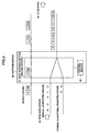
- Fig. 4 is an illustration, describing packet transfer according to one embodiment of the present invention.
- the terminal 10a transfers data through the dedicated channel because transferred data is equal to or greater than a predetermined value
- the terminals 10b, 10c transfer data through the shared channel because such transferred data is less than the predetermined value.
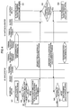
- the control section 22 measures a quantity of data residing in the data buffer 23a of the terminal 10a-dedicated channel (using the measurement means 103 in Fig. 9) when the data is transferred from the terminal 10a through the preceding dedicated channel between the base station 20 and the switching center 30 during a single channel mode (at steps S21 and S31).
- the control section 22 compares the above data quantity in the data buffer 23a with a predetermined delay data quantity-generating value, and then determines whether such a data quantity is equal to or greater than the delay data quantity-generating value (at step S22).
- step S22 When the determination in step S22 results in "YES”, then the control section 22 requests the switching center 30 through the shared channel to allocate a further dedicated channel (hereinafter called an “additional dedicated channel") to the terminal 10a (at step S23).
- a further dedicated channel hereinafter called an “additional dedicated channel”
- the quantity of data residing in the data buffer 23a is "2" (see Fig. 2), and assume that the delay data quantity-generating value is "2" as well. In this state, the above request for allocation is made.
- the switching center 30 determines whether the additional dedicated channel can be allocated to the terminal 10a (at step S32).
- step S32 When the determination in step S32 results in "YES”, then the switching center 30 sends such a result to the base station 20.
- the base station 20 checks such a response from the switching center 30 to determine whether the additional dedicated channel can be allocated to the terminal 10a (at step S24).
- step S24 When the determination in step S24 results in "YES”, then the control section 22 controls respective operations of the mode-switching section (sending side) 21 and the mode-switching section (receiving side) (not shown) in the base station 20, and then sets them from the single channel mode into a multi-channel mode (at step S25).
- the control section 32 in the switching center 30 controls respective operations of the mode-switching section (receiving side) 31 and the mode-switching section (sending side) (not shown), and then sets them from the single channel mode into the multi-channel mode (at step S33).
- the mode-switching section (sending) 21 in the base station 20 sends data through the multi-channel including the terminal 10a-dedicated channel and the terminal 10a-additional dedicated channel in order to prevent a quantity of data residing in the data buffer 23a of the terminal 10a-dedicated channel from being equal to or greater than the delay data quantity-generating value.
- the mode-switching section (receiving side) 31 in the switching center 30 transfers data by received data (packets) being rearranged in the order of a sequence number. For example, as illustrated in Fig.
- the packets transmitted through the terminal 10a-dedicated channel and the terminal 10a-additional dedicated channel are arranged in the order of the sequence number by means of the rearrangement means 204 in Fig. 10 before being transmitted to the network 40.
- the switching center 30 (the multi-receiving control means 205 in Fig. 10) requests the base station 20 to resend data having an expected sequence number when such data needs to be resent from the base station 20 to the switching center 30 because the switching center 30 does not receive the data from the base station 20 after a certain period of time has elapsed.
- both of the base station 20 and the switching center 30 use the shared channel to confirm the absence of data transferred through the terminal 10a-additional dedicated channel (using the multi-receiving release means 106 and 206 in Fig. 9 and 10, respectively). Thereafter, the additional dedicated channel is released from the terminal 10a, thereby causing the mode-switching sections to switch over to the single channel mode.
- the delay data quantity-generating value and the delay data quantity-restoring value can individually be set according to a number of times of call, and must not be necessarily equal to one another.
- the delay data quantity-generating value and the delay data quantity-restoring value are preferably related as follows: "delay data quantity-generating value” > “delay data quantity-restoring value”
- step S22 When it is determined at step S22 that a quantity of data residing in the data buffer 23a is less than the delay data quantity-generating value, and further when it is determined at step S24 that the additional dedicated channel cannot be allocated to the terminal 10a, then the data is transferred only through the terminal 10a-dedicated channel.
- the switching center 30 measures a queuing data quantity of data transferred to the terminal in the dedicated channel.
- the control section 32 determines whether such a measured value is equal to or greater than a delay data quantity-generating value.
- the switching center 30 requests the base station 20 through the shared channel to allocate the additional dedicated channel to the terminal.
- the base station 20 determines upon such a request from the switching center 30 whether the additional dedicated channel can be allocated to the terminal.
- the base station 20 conveys the result of the determination to the switching center 30 through the shared channel.
- the switching center 30 allocates the additional dedicated channel to the terminal upon receipt of the positive result of the determination from the base station 20. Then, the mode-switching section (sending side) (denoted by reference numeral 201' in Fig. 10) is set from the single channel mode into the multi-channel mode.
- the base station 20 receives data transferred through the multi-channel including the dedicated channel and the addition dedicated channel.
- the mode-switching section (receiving section) in the base station 20 causes received data (packets) to be rearranged in the order of a sequence number by means of the rearrangement means 104 in Fig. 9 before sending the data to the terminal.
- the base station 20 requests the switching station 30 to resend data having an expected sequence number (using the multi-receiving control means 105 in Fig. 9) when such data needs to be resent from the switching station 30 to the base station 20 because the base station 20 does not receive the data from the switching station 30 after a certain period of time has elapsed.
- the switching center 30 determines whether a queuing data quantity of data transferred to the terminal through the dedicated channel is equal to or less than a delay data quantity-restoring value. When the determination results in "YES", then the switching center 30 requests the base station 20 through the shared channel to permit the additional dedicated channel already allocated to the terminal to be released from the terminal. The base station 20 determines upon receipt of such a request from the switching center 30 whether the additional dedicated channel can be released from the terminal. The base station 20 delivers the result of the determination to the switching center 30. The switching center 30 releases the additional dedicated channel from the terminal upon receipt of the positive result of the determination from the base station 20.
- Fig. 5 is an illustration, showing the second embodiment.
- this mobile communication system includes a plurality of terminals 10a-10c, a base station 50 connected to the terminals 10a-10c via wireless lines, and a switching center 60 linked to the base station 50 via wire lines.
- the switching center 60 is linked to a network 40, which is one type of a public network or PSTN.
- the wire line for interconnecting the base station 50 and the switching center 60 includes a shared channel and a dedicated channel.
- the shared channel can be shared by the multiple channels, while the dedicated channel can exclusively be used by one of the terminals.
- Fig. 6 is an illustration, showing a structure of the base station 50 according to the second embodiment.
- the base station 50 includes a sending section 51, a control section 52 for controlling the sending section 51, and a data buffer 53a.
- a receiving section is not illustrated, but is controlled by the control section 52, as is the case with a receiving section 61 in the switching section 60.
- Fig. 7 is an illustration, showing a structure of the switching center 60 according to the second embodiment.
- the switching center 60 includes the receiving section 61 and a control section 62 for controlling the receiving section 61.
- a sending section is controlled by the control section 62, as is the case with the sending section 51 in the base station 50.
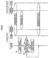
- Fig. 8 is an illustration, describing packet transfer according to the second embodiment.
- the terminal 10a transfers data through the dedicated channel because such transferred data is equal to or greater than a predetermined value
- the terminals 10b, 10c transfer data through the shared channel because such transferred data is less than a predetermined value.
- the control section 52 in the base station 50 measures a quantity of data residing in the data buffer 53a of the terminal 10a-dedicated channel when the data is transferred from the terminal 10a through the terminal 10a-dedicated channel between the base station 50 and the switching center 60 (at step S51).
- the control section 52 compares the measured data quantity with a predetermined delay data quantity-generating value, and then determines whether such a data quantity is equal to or greater than a delay data quantity-generating value (at step S52).
- a data-sending section (the sending section 51 in the base station 50) provides a terminal ID (10a) to terminal 10a-data and then sends the data through the shared channel in order to prevent a quantity of data residing in the data buffer 53a of the terminal 10a-dedicated channel from being equal to or greater than a delay data quantity-generating value.
- a data-receiving section (the receiving section 61 in the switching section 60) eliminates the terminal ID from the data that is received through the shared channel. Then, data from the dedicated channel and data from the shared channel are rearranged in the order of a sequence number, thereby transferring the data.
- step S52 When the determination in step S52 results in "NO", then the data is transferred through the terminal 10a-dedicated channel.
- a first effect of the present invention is to minimize delay in data and discard of data in the mobile communication system, and thus to provide improvements in processing ability and service quality in the base station and the switching center. This is achieved by the feature in which, only when a quantity of data transferred from the terminal is equal to or greater than a predetermined value, then the packet transfer system allocates the dedicated channel to the terminal, and then permits the data to be transferred in the multi-channel mode using the additional dedicated channel, even with an enormous volume of data as well as poor quality of transmission when the data transferred from the terminal is transferred through the dedicated channel.
- a second effect of the present invention is to minimize delay in data and discard of data in the mobile communication system, and thus to provide improvements in processing ability and service quality in the base station and the switching center. This is achieved by the feature in which, only when a quantity of data transferred from the terminal is equal to or greater than a predetermined value, then the packet transfer system allocates the dedicated channel to the terminal, and then permits the data to be transferred in the multi-channel mode using the shared channel, even with a large quantity of data as well as inferior quality of transmission when the data transferred from the terminal is transferred through the dedicated channel.
Landscapes
- Engineering & Computer Science (AREA)
- Computer Networks & Wireless Communication (AREA)
- Signal Processing (AREA)
- Mobile Radio Communication Systems (AREA)
- Data Exchanges In Wide-Area Networks (AREA)
- Small-Scale Networks (AREA)
- Communication Control (AREA)
Abstract
Description
Claims (25)
- A data transfer method in a mobile data communication system including a mobile terminal, a base station connected to said mobile terminal by wireless, and a switching center connected to said base station via a wire line, said data transfer method comprising that,when a quantity of data residing in a dedicated channel of said wire line between said base station and said switching center exceeds a predetermined value, said dedicated channel being exclusively allocated to said mobile terminal, then a further dedicated channel is allocated to said mobile terminal, thereby transmitting data through said multiple dedicated channels.
- A data transfer method as defined in claim 1, wherein when a quantity of data residing in said dedicated channel is equal to or less than a predetermined value that represents restoration of delay, then said further dedicated channel that has been allocated to said mobile terminal is released from said mobile terminal, thereby transmitting data through said dedicated channel that is used earlier than said further dedicated channel.
- A data transfer method in a mobile data communication system including a mobile terminal, a base station connected to said mobile terminal by wireless, and a switching center connected to said base station via a wire line, said data transfer method comprising that,when a quantity of data residing in a dedicated channel of said wire line between said base station and said switching center exceeds a predetermined value, said dedicated channel being exclusively allocated to said mobile terminal, then a shared channel to be shared by multiple mobile terminals is applied to said mobile terminal, thereby transmitting data through said shared channel and said dedicated channel.
- A data transfer method as defined in claim 3, wherein terminal identification information of said mobile terminal is provided to data transmitted through said shared channel.
- A data transfer method as defined in claim 3, wherein when a quantity of data residing in said dedicated channel is equal to or less than a predetermined value that represents restoration of delay, then application of said shared channel to said mobile terminal is stopped, thereby transmitting said data through said dedicated channel that is used earlier than said shared channel.
- A packet transfer method in a communication system including a plurality of terminals, a base station connected to said terminals via wireless lines, and a switching center linked to said base station via a plurality of wire lines, said wire line including a shared channel and a dedicated channel in which said shared channel can be shared by said terminals, while said dedicated channel can be used by only one of said terminals, said packet transfer method permitting data transferred from said terminals to be transferred by said data being separated by a certain length, and when a quantity of data transferred from said terminal is equal to or greater than a predetermined value, then said packet transfer method allocating said dedicated channel to said terminal, thereby permitting said data transferred from said terminal to be transferred through said dedicated channel, said packet transfer method comprising that,in data transfer through said dedicated channel that is allocated to said terminal, when said data transferred from said terminal is waited because of an excessive quantity of transferred data, and further when a queuing data quantity of said data is equal to or greater than a predetermined delay data quantity-generating value, then additional dedicated channel is allocated to said terminal, thereby transferring said data through said dedicated channel and said additional dedicated channel until said queuing data quantity is equal to or less than a predetermined delay data quantity-restoring value.
- A packet transfer method as defined in claim 6, wherein:(a) said base station determines whether a queuing data quantity of data transferred from said terminal is equal to or greater than said delay data quantity-generating value, and when such a determination results in "YES", then said base station requests said switching center to allocate an additional dedicated channel to said terminal;(b) said switching center determines upon receipt of such a request from said base station whether said additional dedicated channel can be allocated to said terminal, and then said switching center delivers result of such a determination to said base station; and,(C) said base station allocates said additional dedicated channel to said terminal upon receipt of positive result of said determination from said switching center.
- A packet transfer method as defined in claim 6, wherein:(d) said base station determines whether a queuing data quantity of data transferred from said terminal is equal to or less than said delay data quantity-restoring value, and when such a determination results in "YES", then said base station requests said switching center to free an additional dedicated channel from said terminal;(e) said switching center determines upon receipt of such a request from said base station whether said additional dedicated channel already allocated to said terminal can be released from said terminal, and then said switching center conveys result of such a determination to said base station; and,(f) said base station releases said additional dedicated channel from said terminal upon receipt of positive result of said determination from said switching center.
- A packet transfer method as defined in claim 6, wherein said delay data quantity-generating value and said delay data quantity-restoring value are individually be set according to a number of times of call.
- A packet transfer method in a communication system including a plurality of terminals, a base station connected to said terminals via wireless lines, and a switching center linked to said base station via a plurality of wire lines, said wire line including a shared channel and a dedicated channel in which said shared channel can be shared by said terminals, while said dedicated channel can be used by only one of said terminals, said packet transfer method permitting data transferred from said terminals to be transferred by said data being separated by a certain length, and only when a quantity of data transferred to said terminal is equal to or greater than a predetermined value, then said packet transfer method allocating said dedicated channel to said terminal, thereby permitting transferred data from said terminal to be transferred through said dedicated channel, said packet transfer method comprising that,in said dedicated channel allocated to said terminal, when data transferred to said terminal is waited because of an excessive quantity of transferred data, and further when a queuing data quantity of said data is equal to or greater than a predetermined delay data quantity-generating value, then another dedicated channel (hereinafter called an "additional dedicated channel") is allocated to said terminal, thereby transferring said data through said additional dedicated channel until said queuing data quantity is equal to or less than a predetermined delay data quantity-restoring value.
- A packet transfer method as defined in claim 10, wherein:(a) said switching center determines whether a queuing data quantity of data transferred to said terminal is equal to or greater than said delay data quantity-generating value, and when such a determination results in "YES", then said switching center requests said base station to allocate an additional dedicated channel to said terminal;(b) said base station determines upon receipt of such a request from said switching center whether said additional dedicated channel can be allocated to said terminal, and then said base station delivers result of such a determination to said switching center; and,(c) said switching center allocates said additional dedicated channel to said terminal upon receipt of positive result of said determination from said base station.
- A packet transfer method as defined in claim 10, wherein:(d) said switching center determines whether a queuing data quantity of data transferred to said terminal is equal to or less than said delay data quantity-restoring value, and when such a determination results in "YES", then said switching center requests said base station to release an additional dedicated channel from said terminal;(e) said base station determines upon receipt of such a request from said switching center whether said additional dedicated channel allocated to said terminal can be released from said terminal, and then said base station conveys result of such a determination to said switching center; and,(f) said switching center releases said additional dedicated channel from said terminal upon receipt of positive result of said determination from said base station.
- A packet transfer method as defined in claim 10, wherein said delay data quantity-generating value and said delay data quantity-restoring value are individually be set according to a number of times of call.
- A packet transfer method in a communication system including a plurality of terminals, a base station connected to said terminals via wireless lines, and a switching center linked to said base station via a plurality of wire lines, said wire line including a shared channel and a dedicated channel in which said shared channel can be shared by said terminals, while said dedicated channel can be used by only one of said terminals, said packet transfer method permitting data transferred from said terminals to be transferred by said data being separated by a certain length, and when a quantity of data transferred from said terminal is equal to or greater than a predetermined value, then said packet transfer method allocating said dedicated channel to said terminal, thereby permitting said data transferred from said terminal to be transferred through said dedicated channel, said packet transfer method comprising that,in said dedicated channel exclusively allocated to said terminal, when data transferred from said terminal is waited because of an excessive quantity of transferred data, and further when a queuing data quantity of said data is equal to or greater than a delay data quantity-generating value, then a terminal ID is provided to said transferred data in order to prevent said queuing data quantity from being equal to or greater than said delay data quantity-generating value, thereby transferring data through said shared channel.
- A packet transfer method as defined in claim 14, wherein said delay data quantity-generating value can be set according to a number of times of call.
- A packet transfer method in a communication system including a plurality of terminals, a base station connected to said terminals via wireless lines, and a switching center linked to said base station via a plurality of wire lines, said wire line including a shared channel and a dedicated channel in which said shared channel can be shared by said terminals, while said dedicated channel can be used by only one of said terminals, said packet transfer method permitting data transferred from said terminals to be transferred by said data being separated by a certain length, and when a quantity of data transferred from said terminal is equal to or greater than a predetermined value, then said packet transfer method allocating said dedicated channel to said terminal, thereby permitting said data transferred from said terminal to be transferred through said dedicated channel, said packet transfer method comprising that,in said dedicated channel exclusively allocated to said terminal, when data transferred to said terminal is waited because of an excessive quantity of transferred data, and further when a queuing data quantity of said data is equal to or greater than a delay data quantity-generating value, then a terminal ID is provided to said transferred data in order to prevent said queuing data quantity from being equal to or greater than said delay data quantity-generating value, thereby transferring data through said shared channel.
- A packet transfer method as defined in claim 16, wherein said delay data quantity-generating value can be set according to a number of times of call.
- A packet transfer system including a plurality of terminals, a base station connected to said terminals via wireless lines, and a switching center linked to said base station via a plurality of wire lines, said wire line including a shared channel and a dedicated channel in which said shared channel can be shared by said terminals, while said dedicated channel can be used by only one of said terminals, said packet transfer system permitting data transferred from said terminals to be transferred by said data being separated by a certain length in a state of a sequence number being provided to said data, and only when a quantity of data transferred to said terminal is equal to or greater than a predetermined value, then said packet transfer system allocating said dedicated channel to said terminal, thereby permitting transferred data from said terminal to be transferred through said dedicated channel, comprising that,said base station includes:a measurement means permitting a queuing data quantity of data transferred from said terminal to be counted for each dedicated channel;a mode-switching means for switching between a single channel mode and a multi-channel mode, said single channel mode permitting said dedicated channel to be applied to said terminal, said multi-channel mode permitting said dedicated channel and an additional dedicated channel to be applied together to said terminal;a control means comparing a count value obtained by said measurement means with a predetermined delay data quantity-generating value, and then providing control such as to switch said mode-switching means from said single channel mode into said multi-channel mode when said count value is greater than said delay data quantity-generating value based on result of such a comparison, said control means further comparing a count value obtained by said measurement means with a predetermined delay data quantity-restoring value, and then providing control such as to switch said mode-switching means from said multi-channel mode into said single channel mode when said count value is equal to or less than said delay data quantity-restoring value based on result of such a comparison;a rearrangement means permitting data to said terminal to be rearranged in order of a sequence number upon receipt of said data when said mode-switching means switches from said single channel mode into said multi-channel mode;a multi-receiving control means requesting said switching center to resend data having an expected sequence number when such data needs to be resent from said switching center to said base station because said base station does not receive said data from said switching center after a certain period of time has elapsed; and,a multi-receiving release means confirming absence of transferred data through said additional dedicated channel when said mode-switching means switches from said multi-channel mode into said single channel mode.
- A packet transfer system as defined in claim 18, wherein said delay data quantity-generating value and said delay data quantity-restoring value are individually be set according to a number of times of call.
- A packet transfer system including a plurality of terminals, a base station connected to said terminals via wireless lines, and a switching center linked to said base station via a plurality of wire lines, said wire line including a shared channel and a dedicated channel in which said shared channel can be shared by said terminals, while said dedicated channel can be used by only one of said terminals, said packet transfer system permitting data transferred from said terminals to be transferred by said data being separated by a certain length in a state of a sequence number being provided to said data, and only when a quantity of data transferred to said terminal is equal to or greater than a predetermined value, then said packet transfer system allocating said dedicated channel to said terminal, thereby permitting transferred data from said terminal to be transferred through said dedicated channel, comprising that,said switching center includes:a measurement means permitting a queuing data quantity of data transferred to said terminal to be counted for each dedicated channel;a mode-switching means for switching between a single channel mode and a multi-channel mode, said single channel mode permitting said dedicated channel being applied to said terminal, said multi-channel mode permitting said dedicated channel and an additional dedicated channel to be applied together to said terminal;a control means comparing a count value obtained by said measurement means with a predetermined delay data quantity-generating value, and then permitting said mode-switching means to switch from said single channel mode into said multi-channel mode based on result of such a comparison, said control means further comparing a count value obtained by said measurement means with a predetermined delay data quantity-restoring value, and then permitting said mode-switching means to switch from said multi-channel mode into said single channel mode based on result of such a comparison;a rearrangement means permitting data from said terminal to be rearranged in order of a sequence number upon receipt of said data when said mode-switching means switches from said single channel mode into said multi-channel mode;a multi-receiving control means requesting said base station to resend data having an expected sequence number when such data needs to be resent from said base station to said switching center because said switching center does not receive said data from said base station after a certain period of time has elapsed; and,a multi-receiving release means confirming absence of transferred data through said additional dedicated channel when said mode-switching means switches from said multi-channel mode into said single channel mode.
- A packet transfer system as defined in claim 20, wherein said delay data quantity-generating value and said delay data quantity-restoring value are individually be set according to a number of times of call.
- A packet transfer system including a plurality of terminals, a base station connected to said terminals via wireless lines, and a switching center linked to said base station via a plurality of wire lines, said wire line including a shared channel and a dedicated channel in which said shared channel can be shared by said terminals, while said dedicated channel can be used by only one of said terminals, said packet transfer system permitting data transferred from said terminals to be transferred by said data being separated by a certain length in a state of a sequence number being provided to said data, and when a quantity of data transferred to said terminal is equal to or greater than a predetermined value, then said packet transfer system allocating said dedicated channel to said terminal, thereby permitting said data transferred from said terminal to be transferred through said dedicated channel, comprising that,said base station includes:a measurement means permitting a queuing data quantity of data transferred from said terminal to be counted for each dedicated channel;a rearrangement means permitting data to be rearranged in order of a sequence number in order to allow for multi-receiving of said dedicated channel and said shared channel, even when said single dedicated channel is used; and,a multi-receiving control means requesting said switching center to resend data having an expected sequence number when such data needs to be resent from said switching center to said base station because said base station does not receive said data from said switching center after a certain period of time has elapsed.
- A packet transfer system including a plurality of terminals, a base station connected to said terminals via wireless lines, and a switching center linked to said base station via a plurality of wire lines, said wire line including a shared channel and a dedicated channel in which said shared channel can be shared by said terminals, while said dedicated channel can be used by only one of said terminals, said packet transfer system permitting data transferred from said terminals to be transferred by said data being separated by a certain length in a state of a sequence number being provided to said data, and when a quantity of data transferred to said terminal is equal to or greater than a predetermined value, then said packet transfer system allocating said dedicated channel to said terminal, thereby permitting said data transferred from said terminal to be transferred through said dedicated channel, comprising that,said switching center includes:a measurement means permitting a queuing data quantity of data transferred to said terminal to be counted for each dedicated channel;a rearrangement means permitting data to be rearranged in order of a sequence number in order to allow for multi-receiving of said dedicated channel and said shared channel, even when said single dedicated channel is used; and,a multi-receiving control means requesting said base station to resend data having an expected sequence number when such data needs to be resent from said base station to said switching center because said switching center does not receive said data from said base station after a certain period of time has elapsed.
- A packet transfer system including a plurality of terminals, a base station connected to said terminals via wireless lines, and a switching center linked to said base station via a plurality of wire lines, said wire line including a shared channel and a dedicated channel in which said shared channel can be shared by said terminals, while said dedicated channel can be used by only one of said terminals, said packet transfer system permitting data transferred from said terminals to be transferred by said data being separated by a certain length in a state of a sequence number being provided to said data, and only when a quantity of data transferred to said terminal is equal to or greater than a predetermined value, then said packet transfer system allocating said dedicated channel to said terminal, thereby permitting transferred data from said terminal to be transferred through said dedicated channel, comprising that,said base station includes:a measurement means permitting a queuing data quantity of data transferred from said terminal to be counted for each dedicated channel;a mode-switching means for switching between a single channel mode and a multi-channel mode, said single channel mode permitting said dedicated channel to be applied to said terminal, said multi-channel mode permitting said dedicated channel and an additional dedicated channel to be applied together to said terminal;a control means comparing a count value obtained by said measurement means with a predetermined delay data quantity-generating value, and then providing control such as to switch said mode-switching means from said single channel mode into said multi-channel mode when said count value is greater than said delay data quantity-generating value based on result of such a comparison, said control means further comparing a count value obtained by said measurement means with a predetermined delay data quantity-restoring value, and then providing control such as to switch said mode-switching means from said multi-channel mode into said single channel mode when said count value is equal to or less than said delay data quantity-restoring value based on result of such a comparison; and,a means permitting data to said terminal to be rearranged in order of a sequence number upon receipt of said data during said multi-channel mode, and then sending such rearranged data to said terminal.
- A packet transfer system including a plurality of terminals, a base station connected to said terminals via wireless lines, and a switching center linked to said base station via a plurality of wire lines, said wire line including a shared channel and a dedicated channel in which said shared channel can be shared by said terminals, while said dedicated channel can be used by only one of said terminals, said packet transfer system permitting data transferred from said terminals to be transferred by said data being separated by a certain length in a state of a sequence number being provided to said data, and only when a quantity of data transferred to said terminal is equal to or greater than a predetermined value, then said packet transfer system allocating said dedicated channel to said terminal, thereby permitting transferred data from said terminal to be transferred through said dedicated channel, comprising that,said switching center includes:a measurement means permitting a queuing data quantity of data transferred to said terminal to be counted for each dedicated channel;a mode-switching means for switching between a single channel mode and a multi-channel mode, said single channel mode permitting said dedicated channel to be applied to said terminal, said multi-channel mode permitting said dedicated channel and an additional dedicated channel to be applied to said terminal;a control means comparing a count value obtained by said measurement means with a predetermined delay data quantity-generating value, and then permitting said mode-switching means to switch from said single channel mode into said multi-channel mode based on result of such a comparison, said control means further comparing a count value obtained by said measurement means with a predetermined delay data quantity-restoring value, and then permitting said mode-switching means to switch from said multi-channel mode into said single channel mode based on result of such a comparison; and,a means permitting data from said terminal to be rearranged in order of a sequence number upon receipt of said data during said multi-channel mode, and then sending such rearranged data to a telephone network.
Applications Claiming Priority (2)
| Application Number | Priority Date | Filing Date | Title |
|---|---|---|---|
| JP19532999 | 1999-07-09 | ||
| JP19532999A JP3546765B2 (en) | 1999-07-09 | 1999-07-09 | Packet transfer method and system |
Publications (2)
| Publication Number | Publication Date |
|---|---|
| EP1067810A2 true EP1067810A2 (en) | 2001-01-10 |
| EP1067810A3 EP1067810A3 (en) | 2001-09-26 |
Family
ID=16339367
Family Applications (1)
| Application Number | Title | Priority Date | Filing Date |
|---|---|---|---|
| EP20000114298 Withdrawn EP1067810A3 (en) | 1999-07-09 | 2000-07-04 | Packet transfer method and system |
Country Status (4)
| Country | Link |
|---|---|
| US (1) | US6771618B1 (en) |
| EP (1) | EP1067810A3 (en) |
| JP (1) | JP3546765B2 (en) |
| KR (1) | KR100373564B1 (en) |
Cited By (3)
| Publication number | Priority date | Publication date | Assignee | Title |
|---|---|---|---|---|
| EP1069790A3 (en) * | 1999-07-10 | 2003-07-02 | Hyundai Electronics Industries Co., Ltd. | Method and apparatus for dynamically assigning channel in asynchronous mobile communication system |
| EP1753256A1 (en) * | 2005-08-09 | 2007-02-14 | Samsung Electronics Co., Ltd. | Method and apparatus for allocating communication resources using a dedicated channel or a shared channel |
| KR100929077B1 (en) * | 2005-08-09 | 2009-11-30 | 삼성전자주식회사 | Communication Resource Allocation Method Using Virtual Circuit Switching Method in Wireless Communication System and Data Transmission / Reception Method of Device and Terminal |
Families Citing this family (20)
| Publication number | Priority date | Publication date | Assignee | Title |
|---|---|---|---|---|
| US6081536A (en) | 1997-06-20 | 2000-06-27 | Tantivy Communications, Inc. | Dynamic bandwidth allocation to transmit a wireless protocol across a code division multiple access (CDMA) radio link |
| US9525923B2 (en) | 1997-12-17 | 2016-12-20 | Intel Corporation | Multi-detection of heartbeat to reduce error probability |
| US6996060B1 (en) | 2001-03-20 | 2006-02-07 | Arraycomm, Inc. | Closing a communications stream between terminals of a communications system |
| US20020118643A1 (en) * | 2000-11-20 | 2002-08-29 | Ofir Shalvi | Method and system for digital communications over a fragmented channel |
| US7339906B1 (en) * | 2001-03-20 | 2008-03-04 | Arraycomm, Llc | Opening a communications stream between a user terminal and a base station |
| KR100834671B1 (en) * | 2002-01-18 | 2008-06-02 | 삼성전자주식회사 | Data service method of mobile communication system |
| JP3898965B2 (en) * | 2002-03-06 | 2007-03-28 | 株式会社エヌ・ティ・ティ・ドコモ | Radio resource allocation method and base station |
| JP3991208B2 (en) | 2002-07-08 | 2007-10-17 | 日本電気株式会社 | Radio access control method and radio access system |
| DE60221669T2 (en) * | 2002-10-16 | 2008-05-21 | Alcatel Lucent | Packet switching for packet data transmission systems in a multi-channel radio arrangement |
| US7471658B2 (en) * | 2002-12-04 | 2008-12-30 | Qualcomm, Incorporated | Adaptive control of transmission procedures |
| WO2006006208A1 (en) * | 2004-07-08 | 2006-01-19 | Mitsubishi Denki Kabushiki Kaisha | Radio base station |
| MX2007004872A (en) * | 2004-10-20 | 2007-07-04 | Qualcomm Inc | MULTIPLE FREQUENCY BAND OPERATION IN WIRELESS NETWORKS. |
| KR101002843B1 (en) * | 2006-02-02 | 2010-12-21 | 한국과학기술원 | Signal transceiving device and method in communication system |
| KR100709809B1 (en) * | 2006-02-06 | 2007-04-24 | 미쓰비시덴키 가부시키가이샤 | Station communication device |
| WO2007108636A1 (en) | 2006-03-20 | 2007-09-27 | Samsung Electronics Co., Ltd. | Method and apparatus for allocating and identifying frequency resources in a frequency division multiple access system |
| KR101033519B1 (en) * | 2007-12-18 | 2011-05-09 | 삼성전자주식회사 | Scheduling device and method for proportional resource allocation among mobile virtual network operators |
| KR101441500B1 (en) | 2008-06-20 | 2014-11-04 | 삼성전자주식회사 | Apparatus and method for transmitting a sounding reference signal in an uplink wireless communication system using multiple antennas and sounding reference signal hopping |
| JP5010573B2 (en) * | 2008-11-27 | 2012-08-29 | 株式会社東芝 | Wireless device and control method thereof |
| CN102804885B (en) | 2009-06-17 | 2015-12-16 | 富士通株式会社 | Communicator, communication system and communication means |
| US9912709B2 (en) | 2014-09-30 | 2018-03-06 | Level 3 Communications, Llc | Allocating capacity of a network connection to data streams based on type |
Family Cites Families (16)
| Publication number | Priority date | Publication date | Assignee | Title |
|---|---|---|---|---|
| US4980886A (en) * | 1988-11-03 | 1990-12-25 | Sprint International Communications Corporation | Communication system utilizing dynamically slotted information |
| JPH02143637A (en) | 1988-11-24 | 1990-06-01 | Nec Corp | Outgoing line selection system |
| JP3079793B2 (en) | 1992-09-18 | 2000-08-21 | 株式会社日立製作所 | Congestion control method and call admission control method |
| JP2955175B2 (en) * | 1994-02-02 | 1999-10-04 | エヌ・ティ・ティ移動通信網株式会社 | Transmission method between stations |
| JPH0856378A (en) * | 1994-08-12 | 1996-02-27 | Saitama Nippon Denki Kk | Mobile object packet communication system |
| JPH08307336A (en) * | 1995-05-08 | 1996-11-22 | Fujitsu Ltd | Transmission path allocation method for mobile communication system |
| US5673259A (en) * | 1995-05-17 | 1997-09-30 | Qualcomm Incorporated | Random access communications channel for data services |
| JPH0951569A (en) * | 1995-08-09 | 1997-02-18 | N T T Ido Tsushinmo Kk | Mobile communication network system |
| JPH09214459A (en) | 1996-01-31 | 1997-08-15 | Nippon Telegr & Teleph Corp <Ntt> | TDMA communication system |
| JP3315588B2 (en) | 1996-05-16 | 2002-08-19 | 株式会社日立製作所 | ATM switch for traffic flow control |
| JP3471588B2 (en) * | 1997-10-30 | 2003-12-02 | 株式会社エヌ・ティ・ティ・ドコモ | Packet data bandwidth control method and packet switching network system in packet switching network |
| JPH11313025A (en) * | 1998-04-24 | 1999-11-09 | Japan Radio Co Ltd | Data communication method |
| US6594238B1 (en) * | 1998-06-19 | 2003-07-15 | Telefonaktiebolaget Lm Ericsson (Publ) | Method and apparatus for dynamically adapting a connection state in a mobile communications system |
| US6483820B1 (en) * | 1999-03-22 | 2002-11-19 | Ericsson Inc. | System and method for dynamic radio resource allocation for non-transparent high-speed circuit-switched data services |
| US6519461B1 (en) * | 1999-10-29 | 2003-02-11 | Telefonaktiebolaget Lm Ericsson (Publ) | Channel-type switching from a common channel to a dedicated channel based on common channel load |
| US6594241B1 (en) * | 1999-12-08 | 2003-07-15 | Telefonaktiebolaget Lm Ericsson (Publ) | Channel-type switching control |
-
1999
- 1999-07-09 JP JP19532999A patent/JP3546765B2/en not_active Expired - Fee Related
-
2000
- 2000-07-04 EP EP20000114298 patent/EP1067810A3/en not_active Withdrawn
- 2000-07-07 US US09/612,556 patent/US6771618B1/en not_active Expired - Fee Related
- 2000-07-08 KR KR10-2000-0039105A patent/KR100373564B1/en not_active Expired - Fee Related
Cited By (5)
| Publication number | Priority date | Publication date | Assignee | Title |
|---|---|---|---|---|
| EP1069790A3 (en) * | 1999-07-10 | 2003-07-02 | Hyundai Electronics Industries Co., Ltd. | Method and apparatus for dynamically assigning channel in asynchronous mobile communication system |
| EP1753256A1 (en) * | 2005-08-09 | 2007-02-14 | Samsung Electronics Co., Ltd. | Method and apparatus for allocating communication resources using a dedicated channel or a shared channel |
| KR100929077B1 (en) * | 2005-08-09 | 2009-11-30 | 삼성전자주식회사 | Communication Resource Allocation Method Using Virtual Circuit Switching Method in Wireless Communication System and Data Transmission / Reception Method of Device and Terminal |
| US7948941B2 (en) | 2005-08-09 | 2011-05-24 | Samsung Electronics Co., Ltd. | Method and apparatus for allocating communication resources using virtual circuit switching in a wireless communication system and method for transmitting and receiving data in a mobile station using the same |
| US8274944B2 (en) | 2005-08-09 | 2012-09-25 | Samsung Electronics Co., Ltd. | Method and apparatus for allocating communication resources using virtual circuit switching in a wireless communication system and method for transmitting and receiving data in a mobile station using the same |
Also Published As
| Publication number | Publication date |
|---|---|
| JP2001024706A (en) | 2001-01-26 |
| JP3546765B2 (en) | 2004-07-28 |
| US6771618B1 (en) | 2004-08-03 |
| KR100373564B1 (en) | 2003-02-25 |
| EP1067810A3 (en) | 2001-09-26 |
| KR20010015251A (en) | 2001-02-26 |
Similar Documents
| Publication | Publication Date | Title |
|---|---|---|
| EP1067810A2 (en) | Packet transfer method and system | |
| US5461627A (en) | Access protocol for a common channel wireless network | |
| EP0606282B1 (en) | Method for realising a group call in a digital radio network | |
| EP0568658B1 (en) | Method of assigning a control channel as a temporary voice/data channel in a radio communications system | |
| KR960006465B1 (en) | Method for dynamically allocating data channels on a trunked communication system | |
| EP1182895A1 (en) | Method and apparatus for performing a voice dispatch call in a digital communication system | |
| CN1075329C (en) | Method for allocating wireless communication channels | |
| AU7433598A (en) | A method for packet switched data transmission | |
| US6229802B1 (en) | Method for packet switched data transmission | |
| US20050021804A1 (en) | Method and system for controlling the transmission of media streams | |
| US8830898B2 (en) | Fast inter system push to talk operation | |
| KR101391486B1 (en) | Allocating traffic channels in a communications system | |
| EP0984591B1 (en) | Packet transfer system | |
| EP0671109B1 (en) | Call set-up in a transmission trunking radio system | |
| JP2632550B2 (en) | ISDN subscriber wireless communication system | |
| US6611505B1 (en) | Control signal processor and communication system | |
| EP1386465B1 (en) | Method and system for controlling the transmission of media streams | |
| RU2384002C2 (en) | Method of controlling data packet transmission | |
| KR0148898B1 (en) | Trs system | |
| JP2002010331A (en) | Mobile communication system and increasing/decreasing method of non-voice channel for same | |
| JPH10322758A (en) | ISDN service method in multi-way multiplex communication system | |
| EP1187500A1 (en) | Method for controlling a logical link between a terminal and a fixed station in a wireless multiple access communication system and corresponding fixed station | |
| KR19990008910A (en) | Control packet structure for providing packet service and user data transmission method using same | |
| JP2000069549A (en) | Communication bandwidth control method | |
| JP2001103543A (en) | Wireless channel assignment method and wireless communication system |
Legal Events
| Date | Code | Title | Description |
|---|---|---|---|
| PUAI | Public reference made under article 153(3) epc to a published international application that has entered the european phase |
Free format text: ORIGINAL CODE: 0009012 |
|
| AK | Designated contracting states |
Kind code of ref document: A2 Designated state(s): DE FR SE Kind code of ref document: A2 Designated state(s): AT BE CH CY DE DK ES FI FR GB GR IE IT LI LU MC NL PT SE |
|
| AX | Request for extension of the european patent |
Free format text: AL;LT;LV;MK;RO;SI |
|
| PUAL | Search report despatched |
Free format text: ORIGINAL CODE: 0009013 |
|
| AK | Designated contracting states |
Kind code of ref document: A3 Designated state(s): AT BE CH CY DE DK ES FI FR GB GR IE IT LI LU MC NL PT SE |
|
| AX | Request for extension of the european patent |
Free format text: AL;LT;LV;MK;RO;SI |
|
| RIC1 | Information provided on ipc code assigned before grant |
Free format text: 7H 04Q 7/30 A, 7H 04J 3/16 B |
|
| 17P | Request for examination filed |
Effective date: 20011022 |
|
| 17Q | First examination report despatched |
Effective date: 20020219 |
|
| AKX | Designation fees paid |
Free format text: DE FR SE |
|
| STAA | Information on the status of an ep patent application or granted ep patent |
Free format text: STATUS: THE APPLICATION IS DEEMED TO BE WITHDRAWN |
|
| 18D | Application deemed to be withdrawn |
Effective date: 20020903 |