EP1067782A2 - Image display device and displaying method - Google Patents
Image display device and displaying method Download PDFInfo
- Publication number
- EP1067782A2 EP1067782A2 EP00114047A EP00114047A EP1067782A2 EP 1067782 A2 EP1067782 A2 EP 1067782A2 EP 00114047 A EP00114047 A EP 00114047A EP 00114047 A EP00114047 A EP 00114047A EP 1067782 A2 EP1067782 A2 EP 1067782A2
- Authority
- EP
- European Patent Office
- Prior art keywords
- image
- frame
- current frame
- sub
- judging
- Prior art date
- Legal status (The legal status is an assumption and is not a legal conclusion. Google has not performed a legal analysis and makes no representation as to the accuracy of the status listed.)
- Granted
Links
Images


Classifications
-
- H—ELECTRICITY
- H04—ELECTRIC COMMUNICATION TECHNIQUE
- H04N—PICTORIAL COMMUNICATION, e.g. TELEVISION
- H04N5/00—Details of television systems
- H04N5/44—Receiver circuitry for the reception of television signals according to analogue transmission standards
- H04N5/445—Receiver circuitry for the reception of television signals according to analogue transmission standards for displaying additional information
- H04N5/45—Picture in picture, e.g. displaying simultaneously another television channel in a region of the screen
-
- H—ELECTRICITY
- H04—ELECTRIC COMMUNICATION TECHNIQUE
- H04N—PICTORIAL COMMUNICATION, e.g. TELEVISION
- H04N21/00—Selective content distribution, e.g. interactive television or video on demand [VOD]
- H04N21/40—Client devices specifically adapted for the reception of or interaction with content, e.g. set-top-box [STB]; Operations thereof
- H04N21/43—Processing of content or additional data, e.g. demultiplexing additional data from a digital video stream; Elementary client operations, e.g. monitoring of home network or synchronising decoder's clock; Client middleware
- H04N21/431—Generation of visual interfaces for content selection or interaction; Content or additional data rendering
- H04N21/4312—Generation of visual interfaces for content selection or interaction; Content or additional data rendering involving specific graphical features, e.g. screen layout, special fonts or colors, blinking icons, highlights or animations
- H04N21/4316—Generation of visual interfaces for content selection or interaction; Content or additional data rendering involving specific graphical features, e.g. screen layout, special fonts or colors, blinking icons, highlights or animations for displaying supplemental content in a region of the screen, e.g. an advertisement in a separate window
-
- H—ELECTRICITY
- H04—ELECTRIC COMMUNICATION TECHNIQUE
- H04N—PICTORIAL COMMUNICATION, e.g. TELEVISION
- H04N7/00—Television systems
- H04N7/01—Conversion of standards, e.g. involving analogue television standards or digital television standards processed at pixel level
- H04N7/0117—Conversion of standards, e.g. involving analogue television standards or digital television standards processed at pixel level involving conversion of the spatial resolution of the incoming video signal
- H04N7/012—Conversion between an interlaced and a progressive signal
-
- H—ELECTRICITY
- H04—ELECTRIC COMMUNICATION TECHNIQUE
- H04N—PICTORIAL COMMUNICATION, e.g. TELEVISION
- H04N21/00—Selective content distribution, e.g. interactive television or video on demand [VOD]
- H04N21/40—Client devices specifically adapted for the reception of or interaction with content, e.g. set-top-box [STB]; Operations thereof
- H04N21/41—Structure of client; Structure of client peripherals
- H04N21/426—Internal components of the client ; Characteristics thereof
Definitions
- the present invention relates to an image display device and displaying method, and more particularly to an image display device and displaying method of decoding binary image data compressed in the MPEG (Motion Picture Expert Group)-2, for displaying the same data.
- MPEG Motion Picture Expert Group
- scanning method of a moving picture comprises a sequential scanning method and an interlaced scanning method (interlaced scan: skip scan).
- sequential scanning all the pixels within one frame are the data of the same time; while, in the interlaced scan, image data of different time is repeated by turns in every other line.
- image compression of the MPEG-2 supports the both methods; the CRT display of a computer, however, displays images in the sequential scanning, thereby deteriorating the image quality in displaying the interlaced scanned moving picture due to the motion between fields. Therefore, in order to prevent from this image degradation, it is preferable to perform scan conversion (this meaning will be described later) on a moving picture of the interlaced scan.
- a method of detecting motion between frames of a moving image is disclosed in JP-A-06-205375, and JP-A-62-72287 (hereinafter, referred to as article 1 and article 2 respectively).
- the method disclosed in the article 1 and the article 2 is a method for detecting motion of an image while comparing the pixel data of the current frame with that one of the prior frame, with the pixel data of the prior frame stored in advance.
- an example of a digital moving image decoder is disclosed in JP-A-10-191257 (hereinafter, referred to as article 3).
- the method disclosed in the article 1 and the article 2 is defective in using extra memory area because of requiring the processing for storing the prior frame into a memory. Further, it is defective in delaying the processing speed because of requiring the processing for detecting motion of the pixel data.
- the article 3 never includes a way for solving these defects.
- An object of the present invention is to provide an image display device and displaying method capable of judging the portion with motion (moving image portion) and the portion without motion (static image portion) in the images during playback of moving images, in a simpler way than that of the conventional image display device and displaying method.
- an image display device for playing-back and displaying binary image data after decoding the above by the frame, comprises
- the present invention is designed to judge whether the current frame is a moving image or a static image, based on the time interval between frames having been decoded in the past, thereby making it possible to judge it in a simpler device and method than the conventional one.
- the image judging means judges the current frame to be a static image when the time interval between the frames is a predetermined value and the more, and judges the current frame to be a moving image when the same time interval is less than the predetermined value.
- the image judging means makes a judgment on an image, based on the frame one ahead of the current frame and the frame two ahead of the current frame.
- the image judging means makes a judgment on an image, based on the frame one ahead of the current frame and the frame two ahead of the current frame,
- the image judging means includes
- the binary image data is an image obtained by interlaced scan
- the frame is formed by a first field and a second field having a difference of a constant time.
- the scan converting means when the image judging means judges the current frame to be a moving image, performs scan conversion on the current frame.
- the scan converting means when the image judging means judges the current frame to be a static image, the scan converting means never performs scan conversion on the current frame.
- the scan converting means when the image judging means judges the current frame to be a moving image, performs scan conversion on the current frame, and,
- an image display device for playing-back and displaying binary image data after decoding the above by the frame, comprises
- the sub-picture combining means combines the sub-picture with the next frame.
- the sub-picture combining means combines the sub-picture with the current frame.
- the sub-picture combining means when the image judging means judges the current frame to be a moving image, the sub-picture combining means combines the sub-picture with the next frame, while when the image judging means judges the current frame to be a static image, the sub-picture combining means combines the sub-picture with the current frame.
- an image displaying method for displaying binary image data after decoding the above by the frame comprising the steps of
- the current frame is judged to be a static image when the time interval between the frames is a predetermined value and the more, and the current frame is judged to be a moving image when the same time interval is less than the predetermined value.
- a judgment about an image is made, based on the frame one ahead of the current frame and the frame two ahead of the current frame.
- the image judging step includes a storing step for storing the time when each frame is decoded, and a judging step for making a judgment on an image based on the time stored in the storing step.
- the binary image data is an image obtained by interlaced scan
- the frame is formed by a first field and a second field having a difference of a constant time.
- the image displaying method further comprises a sub-picture combining step for combining a sub-picture with the frame.
- the sub-picture is combined with the next frame in the sub-picture combining step.
- the sub-picture is combined with the current frame in the sub-picture combining step.
- the sub-picture when the current frame is judged to be a moving image in the image judging step, the sub-picture is combined with the next frame in the sub-picture combining step, while when the current frame is judged to be a static image in the image judging step, the sub-picture is combined with the current frame in the sub-picture combining step.
- the present invention is to improve the playback quality of images, by judging the portion with motion (moving image portion) and the portion without motion (static image portion) during playback of a moving image, in a simpler device than the conventional one, and displaying the above respective portions in a proper way.
- Fig. 1 is a view showing the structure of a first embodiment of an image display device according to the present invention.
- the image display device comprises a storing unit 10, an image data processing unit 20, and a display 40.
- the image data processing unit 20 includes a compression data buffer 21, an image decoding unit 22, an image motion judging unit 23, a display time storing unit 24, a scan converting unit 25, and a frame data buffer 26.
- the storing unit 10 stores an original image 11, for example, compressed by the MPEG-2, for example.
- the original image 11 comprises the moving image portion and the static image portion within its data.
- the decoded image is an image obtained by the interlaced scan and that it has the data of 60 fields (30 frames) a second.
- the imaged data processing unit 20 decodes the image data (original image 11) loaded from the storing unit 10 and sends the image data to the display 40.
- the display 40 is a sequential scanning typed display.
- the image obtained by the interlaced scan includes the data having the time difference of 1/60 second for a frame.
- the data at a time is referred to as the first field
- the data 1/60 second later after the first field is referred to as the second field.
- the first and second fields have the data in every other line. Simultaneous display of the first field data and the second field data causes the quality degradation due to the motion of the image. Therefore, it is necessary to foresee which value the data of the second field was before 1/60 second (at the same time as the first field) and replace the value of the second field with the resultant value.
- the image data of the interlaced scan is converted into the image data of the sequential scanning method. This processing is called scan conversion.
- the portion without motion of the pixel data (static image portion) between fields will not deteriorate in the image quality even if performing no scan conversion and displaying the same portion as it is. It is preferable to perform no scan conversion on the static image portion because the original data can be displayed faithfully.
- the present invention will propose a device and a method of examining the time interval between frames, for judging the presence of any motion of an image simply according to the length of the time interval.
- the time interval between frames is long, it can be judged a static image where no correlation of the data exists between the frames, while if the time interval is short, it can be judged a moving image. Only the examination of the interval between frames can judge a static image or a moving image, thereby speeding up the processing.
- a usual moving image has the data for 24 frames to 60 frames per a second, in the MPEG format. That is, the interval between frames is 16.7 msec to 41.7 msec. Accordingly, in examining the time interval between the prior frame and the frame before the prior frame, during the playback of an image, it can be judged that the usual moving image is being reproduced when the interval is, for example, below 50 msec, and that the static image such as a slide show is being displayed when the interval is 50 msec and the more.
- the display interval between the prior frame and the frame before the prior frame is calculated by the image motion judging unit 23; the resultant interval divides the case where the data is displayed after being scan-converted by the scan converting unit 25 and the case where it is directly displayed without scan conversion.
- the current time is stored in the display time storing unit 24. This time is used for judgment of motion in the next frame.
- the image data displayed is sent to the frame data buffer 26, and displayed on the display 40.
- the operation will be described in the case in which, after loading the original image 11 compressed in the MPEG-2 from the storing unit 10, the compressed MPEG-2 data kept in the compression data buffer 21 is decoded by the image decoding unit 22, the motion of the pixel data within an image is judged by the image motion judging unit 23, and according to the judgment result, the image data is converted from the interlaced scanning data to the sequential scanning data by the scan converting unit 25 and displayed on the display 40.
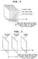
- Figs. 2 and 3 are schematic explanatory diagrams for use in describing the first embodiment
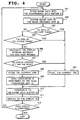
- Fig. 4 is a flow chart showing the operation of the first embodiment.
- the storing unit 10 stores the original image 11 compressed in the MPEG-2 method.
- the image data 11 is loaded in the compression data buffer 21.
- the compressed image data is decoded by the image decoding unit 22.
- the image data is obtained by the interlaced scanning method. Namely, the data includes the image information having different time respectively at even lines and odd lines.
- the interlaced scan has the field data different in every other line, which causes the sequential scanning typed display to deteriorate in the image quality, due to the motion of an image. Therefore, when displaying an image, it is necessary to convert the interlaced scanned image data into the sequential scanned image data.
- whether the frame to be displayed is a frame of the moving image portion or a frame of the static image portion is judged in the following way.
- the time when the data two frames ahead of the frame was displayed is stored.
- the time when the data one frame ahead of the frame was displayed is stored.
- the difference in the display time of these two past frames is calculated.
- small difference of the time means that the original image 11 is sequentially decoded and displayed; therefore, this data is judged to be a moving image. Since in the data judged to be a moving image, there is a possibility of including a motion in the data of an image, scan conversion is performed on the data, which is displayed on the sequential scanning typed display 40.
- the data stored in the buffer 21 is decoded by the image decoding unit 22 (Step 402).
- This image has the image data consisting of different times in every line (difference of 1/60 sec.) because of adopting the interlaced scan.
- the image motion judging unit 23 examines where this frame is positioned (Steps 403 and 405).
- the first frame in the case of YES in Step 403
- the current time is stored (Step 404).
- Step 404 the current time is stored (Step 404).
- Step 406 a comparison of the display time between the latest two frames is made.
- the interval of the display time is T sec. and the more (in the case of YES in Step 407), it is judged to be a static image.
- the interval of the display time is less than T sec. (in the case of NO in Step 407), it is judged to be a moving image.
- the current time is stored (Step 408).
- the decoded video data is transferred to the frame data buffer 26 as it is (Steps 404 and 410). While when it is judged to be a moving image, since scan conversion is necessary, scan conversion is performed by the scan converting unit 25 (Step 409), and the video data is transferred to the frame data buffer 26 (Step 410).
- Step 411 The video data transferred to the frame data buffer 26 is displayed on the display 40 (Step 411). If the display is not completed (in the case of NO in Step 412), this step will be returned to Step 401, where the next frame data is displayed. If the display is completed (in the case of YES in Step 412), the processing will be finished.
- the second embodiment is described in the case where the present invention is adopted to a display reproducing unit of DVD (Digital Versatile Disc).
- This second embodiment proposes a technique for correctly combining a sub-picture after judging motion of video data when the sub-picture (the data of subtitles or the like prepared separately from the video data) is combined with the video during playback of the DVD.
- Fig. 5 is a view showing the structure of the second embodiment.
- the same reference numeral is attached to the same structure as that in Fig. 1 (the first embodiment).
- the second embodiment comprises a storing unit 10 for storing compressed image data, an image data processing unit 20a which operates according to a program control, and a display 40 for displaying the image data.
- the storing unit 10 includes the original image 11 compressed in the MPEG-2 and sub-picture data 12.
- the image data processing unit 20a includes a compression data buffer 21 for keeping the image data loaded from the storing unit 10, an image decoding unit 22 for decoding the compressed MPEG-2 data, an image motion judging unit 23 for judging motion of pixel data of an image, a display time storing unit 24 for storing the time when a frame is displayed, a sub-picture combining unit 30 at the time of video decoding, for combining the sub-picture data decoded in the moving image data, with the video data, a frame data buffer 26 for storing the image data displayed, a sub-picture data buffer 27 for keeping the compressed sub-picture data, and a sub-picture combining unit 29 at the time of sub-picture decoding, for combining the sub-picture with the video data when the video data is a static image.
- the image data decoded by the image data processing unit 20 is displayed on the display 40.
- the video data is stored separately from the sub-picture such as the subtitles, and the sub-picture is superimposed on the video data, thereby to be displayed.
- the sub-picture is combined and displayed during the moving image playback, if the sub-picture is displayed independent of the video decoding processing at the start time of the sub-picture combination after finishing decoding the sub-picture, there occurs a phenomenon that the same video data as that at the display time on the side of the video decoding processing is displayed, thereby damaging the smoothness in the playback.
- the frame 4 will be reproduced again after the frame 4.
- which frame 4 the sub-picture is combined with depends on the internal structure of the image data processing unit 20a.
- the sub-picture fails to be updated and displayed when only the sub-picture is updated during the playback of the static image data.
- the video is the static image data, it is necessary to display the sub-picture independent of the video decoding processing at the time of updating the sub-picture.
- the respective decoding processing of the video and the sub-picture is performed independently by the compression data buffer 21 and the image decoding unit 22, and the sub-picture data buffer 27 and the sub-picture decoding unit 28.
- the display interval between the two past frames is stored in the display time storing unit 24, and the image motion judging unit 23 makes a judgment about a moving image or a static image. The operation of this judgment is the same as that of the first embodiment.
- the sub-picture combination and display is started at the next video frame.
- the sub-picture combination and display is performed at the time of finishing decoding the sub-picture, independent of the video display.
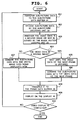
- Fig. 6 is a flow chart showing the operation of the second embodiment. Assume that the video data has been decoded and displayed according to the present invention. With reference to Fig. 6, the sub-picture data 12 of Fig. 5 is transferred to the sub-picture data buffer 27 (Step 601). Next, the data stored in the buffer 27 is decoded by the sub-picture decoding unit 28 (Step 602). The display interval between the two past frames of the video data is examined by the image motion judging unit 23 (Step 603). When the interval of the display time is T sec. and the more (in the case of NO in Step 604), it is judged to be a static image. While when the interval of the display time is less than T sec. (in the case of YES in Step 604), it is judged to be a moving image.
- the sub-picture When it is judged to be a moving image, the sub-picture is not combined with the video data at once to be transferred to the frame data buffer 26, but waits for the next frame of the video data to be decoded (Step 605), and when the decoded frame is transferred to the frame data buffer 26, the sub-picture is combined with the video data by the video decoding time sub-picture combining unit 30 at (Step 606). While, when it is judged to be a static image, the sub-picture is combined with the video data at once by the sub-picture decoding time sub-picture combining unit 29 (Step 607).
- the respectively combined video data is transferred to the frame data buffer 26 (Step 608).
- the video data transferred to the frame data buffer 26 is displayed on the display 40 (Step 609). If the display is not completed (in the case of NO in Step 610), this step will be returned to Step 601, where the next frame data is displayed (simultaneously the decoding processing of the video data is continued). While if the display is completed (in the case of YES in Step 610), the processing is finished.
- the present invention concerns an image display device for displaying the binary image data after decoding it by the frame, which is designed to include an image judging means for judging whether the current frame is a moving image or a static image based on the time interval between the frames having been decoded in the past, thereby enabling the judgment in a simpler device and method than the conventional one.
- the other embodiment of the present invention concerns an image displaying method for displaying the binary image data after decoding it by the frame, including an image judging step for judging whether the current frame is a moving image or a static image based on the time interval between the frames having been decoded in the past, thereby making the same effect as that of the above mentioned invention.
- this image judging means and step enables improvement of the display quality of the static image portion. This is because the interlaced scanned image signal is displayed on the sequential scanning typed display as it is, without scan conversion, because of no motion in an image, when it is judged to be a static image portion.
- this image judging means and step for the sub-picture combination prevents from damaging the smoothness during the playback, because of preventing from displaying one video frame twice at the sub-picture combination time. This is because the sub-picture is combined with the video data of the frame next to the current frame when it is judged to be a moving image portion.
Landscapes
- Engineering & Computer Science (AREA)
- Multimedia (AREA)
- Signal Processing (AREA)
- Computer Graphics (AREA)
- Business, Economics & Management (AREA)
- Marketing (AREA)
- Compression Or Coding Systems Of Tv Signals (AREA)
- Controls And Circuits For Display Device (AREA)
- Television Systems (AREA)
Abstract
Description
Claims (20)
- An image display device for playing-back and displaying binary image data after decoding the above by the frame, comprising:image judging means (23) for judging the current frame to be a moving image or a static image, based on time interval between frames which have been decoded in the past;scan converting means (25) for performing scan conversion on the current frame depending on the judgment result by said image judging means (23); anddisplaying means (40) for displaying the decoded image through sequential scanning.
- A device as set forth in Claim 1, whereinthe binary image data is an image obtained by interlaced scan, and the frame is formed by a first field and a second field having a difference of a constant time.
- A device as set forth in Claim 1 or 2, whereinwhen said image judging means (23) judges the current frame to be a moving image, said scan converting means (25) performs scan conversion on the current frame.
- A device as set forth in Claim 1, 2 or 3, whereinwhen said image judging means (23) judges the current frame to be a static image, said scan converting means (25) never performs scan conversion on the current frame.
- An image display device for playing-back and displaying binary image data after decoding the above by the frame, comprising:image judging means (23) for judging the current frame to be a moving image or a static image, based on time interval between frames which have been decoded in the past;sub-picture combining means (29, 30) for combining a sub-picture with the frame on the judgment result by said image judging means; anddisplaying means (40) for displaying the decoded image through sequential scanning.
- A device as set forth in any one of Claims 1 to 5, whereinsaid image judging means (23) judges the current frame to be a static image when the time interval between the frames is a predetermined value and the more, and judges the current frame to be a moving image when the same time interval is less than the predetermined value.
- A device as set forth in any one of Claims 1 to 6, whereinsaid image judging means (23) makes a judgment on an image, based on the frame one ahead of the current frame and the frame two ahead of the current frame.
- A device as set forth in Claim 5, 6 or 7, whereinsaid image judging means (23) includesa storing unit for storing the time when each frame is decoded, anda judging unit for making a judgment on an image based on the time stored in said storing unit.
- A device as set forth in Claim 5, 6, 7 or 8, whereinwhen said image judging means (23) judges the current frame to be a moving image, said sub-picture combining means (29, 30) combines the sub-picture with the next frame.
- A device as set forth in any one of Claims 5 to 9, whereinwhen said image judging means (23) judges the current frame to be a static image, said sub-picture combining means (29, 30) combines the sub-picture with the current frame.
- An image displaying method for displaying binary image data after decoding the above by the frame, comprising:an image judging step for judging the current frame to be a moving image or a static image, based on time interval between frames which have been decoded in the past;a scan converting step for performing scan conversion on the current frame, depending on the judgment result in said image judging step; anda displaying step for displaying the decoded image through sequential scanning.
- A method as set forth in Claim 11, wherein whereinin said image judging step, the current frame is judged to be a static image when the time interval between the frames is a predetermined value and the more, and the current frame is judged to be a moving image when the same time interval is less than the predetermined value.
- A method as set forth in Claim 11 or 12, whereina judgment about an image is made, based on the frame one ahead of the current frame and the frame two ahead of the current frame.
- A method as set forth in Claim 11, 12 or 13, whereinsaid image judging step includes a storing step for storing the time when each frame is decoded, and a judging step for making a judgment on an image based on the time stored in said storing step.
- A method as set fort in Claim 11, 12, 13 or 14, whereinthe binary image data is an image obtained by interlaced scan, and the frame is formed by a first field and a second field having a difference of a constant time.
- A method as set forth in any one of Claims 11 to 15, whereinwhen the current frame is judged to be a moving image in said image judging step, scan conversion is performed on the current frame in said scan converting step.
- A method as set forth in any one of Claims 11 to 16, whereinwhen the current frame is judged to be a static image in said image judging step, scan conversion is never performed on the current frame in said scan converting step.
- A method as set forth in any one of Claims 11 to 17, further comprisinga sub-picture combining step for combining a sub-picture with the frame.
- A method as set forth in Claim 18, whereinwhen the current frame is judged to be a moving image in said image judging step, the sub-picture is combined with the next frame in said sub-picture combining step.
- A method as set forth in Claim 18 or 19, whereinwhen the current frame is judged to be a static image in said image judging step, the sub-picture is combined with the current frame in said sub-picture combining step.
Applications Claiming Priority (2)
| Application Number | Priority Date | Filing Date | Title |
|---|---|---|---|
| JP19247699A JP3721867B2 (en) | 1999-07-07 | 1999-07-07 | Video display device and display method |
| JP19247699 | 1999-07-07 |
Publications (3)
| Publication Number | Publication Date |
|---|---|
| EP1067782A2 true EP1067782A2 (en) | 2001-01-10 |
| EP1067782A3 EP1067782A3 (en) | 2004-01-28 |
| EP1067782B1 EP1067782B1 (en) | 2005-04-27 |
Family
ID=16291935
Family Applications (1)
| Application Number | Title | Priority Date | Filing Date |
|---|---|---|---|
| EP20000114047 Expired - Lifetime EP1067782B1 (en) | 1999-07-07 | 2000-07-05 | Image display device and displaying method |
Country Status (4)
| Country | Link |
|---|---|
| US (1) | US7143351B1 (en) |
| EP (1) | EP1067782B1 (en) |
| JP (1) | JP3721867B2 (en) |
| DE (1) | DE60019686T2 (en) |
Cited By (2)
| Publication number | Priority date | Publication date | Assignee | Title |
|---|---|---|---|---|
| EP1494469A3 (en) * | 2003-06-30 | 2007-09-19 | Kabushiki Kaisha Toshiba | Television receiver and control method thereof |
| WO2023000216A1 (en) * | 2021-07-21 | 2023-01-26 | 京东方科技集团股份有限公司 | Control apparatus and driving method therefor, and display apparatus |
Families Citing this family (2)
| Publication number | Priority date | Publication date | Assignee | Title |
|---|---|---|---|---|
| KR100945577B1 (en) | 2003-03-11 | 2010-03-08 | 삼성전자주식회사 | Driving device of liquid crystal display and method thereof |
| KR102575743B1 (en) | 2021-10-14 | 2023-09-06 | 네이버 주식회사 | Method and system for image translation |
Family Cites Families (41)
| Publication number | Priority date | Publication date | Assignee | Title |
|---|---|---|---|---|
| DE3517737A1 (en) * | 1985-05-17 | 1986-11-27 | Kernforschungsanlage Jülich GmbH, 5170 Jülich | METHOD AND CIRCUIT ARRANGEMENT FOR TELEVISIONAL RECORDING AND PLAYBACK OF STATIC OR MOVING OBJECTS |
| JPS6272287A (en) | 1985-09-26 | 1987-04-02 | Toshiba Corp | Television signal processing unit |
| JPS63149973A (en) | 1986-12-12 | 1988-06-22 | Mitsubishi Electric Corp | Moving picture coding transmitter |
| JP2749873B2 (en) | 1989-05-30 | 1998-05-13 | キヤノン株式会社 | Image information transmission system |
| US5144688A (en) * | 1990-03-23 | 1992-09-01 | Board Of Regents, The University Of Texas System | Method and apparatus for visual pattern image coding |
| US5355178A (en) * | 1991-10-24 | 1994-10-11 | Eastman Kodak Company | Mechanism for improving television display of still images using image motion-dependent filter |
| US5369449A (en) * | 1991-11-08 | 1994-11-29 | Matsushita Electric Industrial Co., Ltd. | Method for predicting move compensation |
| JPH0756652B2 (en) * | 1992-03-24 | 1995-06-14 | インターナショナル・ビジネス・マシーンズ・コーポレイション | Search for video frame sequence |
| US5233421A (en) * | 1992-04-30 | 1993-08-03 | Thomson Consumer Electronics, Inc. | Video memory system with double multiplexing of video and motion samples in a field memory for motion adaptive compensation of processed video signals |
| JPH0778804B2 (en) * | 1992-05-28 | 1995-08-23 | 日本アイ・ビー・エム株式会社 | Scene information input system and method |
| EP0598516A3 (en) * | 1992-11-05 | 1996-07-03 | Sony Corp | Recording and reproduction of moving images. |
| JPH06205375A (en) | 1992-12-28 | 1994-07-22 | Mitsubishi Precision Co Ltd | Scanning converion system |
| US5481712A (en) * | 1993-04-06 | 1996-01-02 | Cognex Corporation | Method and apparatus for interactively generating a computer program for machine vision analysis of an object |
| WO1994030006A1 (en) * | 1993-06-08 | 1994-12-22 | Faroudja Y C | TELEVISION SIGNAL PROCESSING APPARATUS INCORPORATING MEANS FOR DETECTING 25 FRAME/SECOND MOTION PICTURE FILM SOURCES IN 50 Hz TELEVISION SIGNALS |
| JPH07212766A (en) * | 1994-01-18 | 1995-08-11 | Matsushita Electric Ind Co Ltd | Video compression data switching device |
| US5592226A (en) * | 1994-01-26 | 1997-01-07 | Btg Usa Inc. | Method and apparatus for video data compression using temporally adaptive motion interpolation |
| JP3700196B2 (en) * | 1994-03-29 | 2005-09-28 | ソニー株式会社 | Image processing apparatus and image processing method |
| JP3711571B2 (en) * | 1994-09-29 | 2005-11-02 | ソニー株式会社 | Image coding apparatus and image coding method |
| US5828421A (en) * | 1994-10-11 | 1998-10-27 | Hitachi America, Ltd. | Implementation efficient digital picture-in-picture decoding methods and apparatus |
| WO2004080069A1 (en) * | 1995-01-24 | 2004-09-16 | Hiroki Zenda | Multimedia computer system |
| JP3569992B2 (en) * | 1995-02-17 | 2004-09-29 | 株式会社日立製作所 | Mobile object detection / extraction device, mobile object detection / extraction method, and mobile object monitoring system |
| US5610661A (en) * | 1995-05-19 | 1997-03-11 | Thomson Multimedia S.A. | Automatic image scanning format converter with seamless switching |
| JP3350289B2 (en) | 1995-06-08 | 2002-11-25 | 株式会社日立製作所 | Method and apparatus for transmitting remote information |
| US6057893A (en) * | 1995-12-28 | 2000-05-02 | Sony Corporation | Picture encoding method, picture encoding apparatus, picture transmitting method and picture recording medium |
| US6144972A (en) * | 1996-01-31 | 2000-11-07 | Mitsubishi Denki Kabushiki Kaisha | Moving image anchoring apparatus which estimates the movement of an anchor based on the movement of the object with which the anchor is associated utilizing a pattern matching technique |
| JPH09233458A (en) * | 1996-02-28 | 1997-09-05 | Toshiba Corp | Image selecting method and image selecting apparatus |
| JPH10126749A (en) | 1996-10-14 | 1998-05-15 | Toshiba Corp | Progressive scan converter |
| JP3198980B2 (en) * | 1996-10-22 | 2001-08-13 | 松下電器産業株式会社 | Image display device and moving image search system |
| JP3073948B2 (en) | 1996-10-31 | 2000-08-07 | 松下電器産業株式会社 | Digital video decoding apparatus and digital video decoding method |
| WO1998040874A1 (en) * | 1997-03-10 | 1998-09-17 | Komatsu Ltd. | Image synthesizing device, image conversion device, and methods |
| US6215505B1 (en) * | 1997-06-20 | 2001-04-10 | Nippon Telegraph And Telephone Corporation | Scheme for interactive video manipulation and display of moving object on background image |
| DE69839761D1 (en) * | 1997-10-15 | 2008-09-04 | Nxp Bv | MOTION ESTIMATE |
| JPH11298890A (en) * | 1998-04-13 | 1999-10-29 | Hitachi Ltd | Image data compression or decompression method and apparatus, and image transmission system and monitoring system using the same |
| KR100325253B1 (en) * | 1998-05-19 | 2002-03-04 | 미야즈 준이치롯 | Motion vector search method and apparatus |
| US6278466B1 (en) * | 1998-06-11 | 2001-08-21 | Presenter.Com, Inc. | Creating animation from a video |
| CN1311958A (en) * | 1998-06-11 | 2001-09-05 | 皇家菲利浦电子有限公司 | Trick play signal generation for a digital video recorder |
| JP3209210B2 (en) * | 1999-02-10 | 2001-09-17 | 日本電気株式会社 | Moving image compression method, moving image compression device, and storage medium storing moving image compression program |
| FI106421B (en) * | 1999-03-11 | 2001-01-31 | Nokia Multimedia Network Termi | Method and arrangement for combining video images |
| US6658056B1 (en) * | 1999-03-30 | 2003-12-02 | Sony Corporation | Digital video decoding, buffering and frame-rate converting method and apparatus |
| EP1181818B1 (en) * | 1999-05-21 | 2003-07-30 | Infineon Technologies AG | Method and circuit arrangement for picture-in-picture superimposition of a video image |
| JP2001204045A (en) * | 2000-01-24 | 2001-07-27 | Mitsubishi Electric Corp | Motion detection device |
-
1999
- 1999-07-07 JP JP19247699A patent/JP3721867B2/en not_active Expired - Fee Related
-
2000
- 2000-07-05 EP EP20000114047 patent/EP1067782B1/en not_active Expired - Lifetime
- 2000-07-05 DE DE2000619686 patent/DE60019686T2/en not_active Expired - Lifetime
- 2000-07-06 US US09/611,367 patent/US7143351B1/en not_active Expired - Fee Related
Cited By (3)
| Publication number | Priority date | Publication date | Assignee | Title |
|---|---|---|---|---|
| EP1494469A3 (en) * | 2003-06-30 | 2007-09-19 | Kabushiki Kaisha Toshiba | Television receiver and control method thereof |
| WO2023000216A1 (en) * | 2021-07-21 | 2023-01-26 | 京东方科技集团股份有限公司 | Control apparatus and driving method therefor, and display apparatus |
| US12148374B2 (en) | 2021-07-21 | 2024-11-19 | Hefei Boe Joint Technology Co., Ltd. | Control device and driving method therefor, and display device |
Also Published As
| Publication number | Publication date |
|---|---|
| DE60019686D1 (en) | 2005-06-02 |
| US7143351B1 (en) | 2006-11-28 |
| JP3721867B2 (en) | 2005-11-30 |
| DE60019686T2 (en) | 2005-09-29 |
| JP2001025022A (en) | 2001-01-26 |
| EP1067782B1 (en) | 2005-04-27 |
| EP1067782A3 (en) | 2004-01-28 |
Similar Documents
| Publication | Publication Date | Title |
|---|---|---|
| US6148033A (en) | Methods and apparatus for improving picture quality in reduced resolution video decoders | |
| US20070153904A1 (en) | Motion vector detection method and apparatus | |
| US6668018B2 (en) | Methods and apparatus for representing different portions of an image at different resolutions | |
| JP3222496B2 (en) | Video signal processing device | |
| US20100020233A1 (en) | Video image transmitting device, video image receiving device, video image recording device, video image reproducing device, and video image displaying device | |
| JPH11243543A (en) | Method and apparatus for detecting scene content resulting in a prediction error and using the detected information in a low resolution video decoder | |
| US7197075B2 (en) | Method and system for video sequence real-time motion compensated temporal upsampling | |
| US6842194B1 (en) | Inverse telecine conversion apparatus | |
| EP1067782B1 (en) | Image display device and displaying method | |
| US20050093885A1 (en) | Buffer descriptor structures for communication between decoder and display manager | |
| US6243140B1 (en) | Methods and apparatus for reducing the amount of buffer memory required for decoding MPEG data and for performing scan conversion | |
| US5946037A (en) | Method and apparatus for reordering frames in MPEG coder/decoder | |
| US6907077B2 (en) | Variable resolution decoder | |
| US20070140529A1 (en) | Method and device for calculating motion vector between two images and program of calculating motion vector between two images | |
| US7636490B2 (en) | Deblocking filter process with local buffers | |
| US7050494B1 (en) | Frame display method and apparatus using single field data | |
| US7558429B2 (en) | Image processing method and method for detecting differences between different image macro-blocks | |
| US20060269227A1 (en) | Subpicture display device utilizing micro-processor created subpicture address table and related method | |
| JP3063736B2 (en) | Image scanning method conversion apparatus and method | |
| JP2005521310A (en) | Video signal post-processing method | |
| JP3196753B2 (en) | Image display method and image display device | |
| US6711305B2 (en) | Image processing apparatus and method | |
| KR100416557B1 (en) | Method for reproducing partial interlaced image and apparatus thereof | |
| CN1774079A (en) | Ways to suppress wrong image colors | |
| JPH11110565A (en) | Motion detection device |
Legal Events
| Date | Code | Title | Description |
|---|---|---|---|
| PUAI | Public reference made under article 153(3) epc to a published international application that has entered the european phase |
Free format text: ORIGINAL CODE: 0009012 |
|
| AK | Designated contracting states |
Kind code of ref document: A2 Designated state(s): AT BE CH CY DE DK ES FI FR GB GR IE IT LI LU MC NL PT SE |
|
| AX | Request for extension of the european patent |
Free format text: AL;LT;LV;MK;RO;SI |
|
| PUAL | Search report despatched |
Free format text: ORIGINAL CODE: 0009013 |
|
| AK | Designated contracting states |
Kind code of ref document: A3 Designated state(s): AT BE CH CY DE DK ES FI FR GB GR IE IT LI LU MC NL PT SE |
|
| AX | Request for extension of the european patent |
Extension state: AL LT LV MK RO SI |
|
| 17P | Request for examination filed |
Effective date: 20031216 |
|
| 17Q | First examination report despatched |
Effective date: 20040301 |
|
| GRAP | Despatch of communication of intention to grant a patent |
Free format text: ORIGINAL CODE: EPIDOSNIGR1 |
|
| AKX | Designation fees paid |
Designated state(s): DE FR GB |
|
| GRAS | Grant fee paid |
Free format text: ORIGINAL CODE: EPIDOSNIGR3 |
|
| GRAA | (expected) grant |
Free format text: ORIGINAL CODE: 0009210 |
|
| AK | Designated contracting states |
Kind code of ref document: B1 Designated state(s): DE FR GB |
|
| REG | Reference to a national code |
Ref country code: GB Ref legal event code: FG4D |
|
| REG | Reference to a national code |
Ref country code: IE Ref legal event code: FG4D |
|
| REF | Corresponds to: |
Ref document number: 60019686 Country of ref document: DE Date of ref document: 20050602 Kind code of ref document: P |
|
| PLBE | No opposition filed within time limit |
Free format text: ORIGINAL CODE: 0009261 |
|
| STAA | Information on the status of an ep patent application or granted ep patent |
Free format text: STATUS: NO OPPOSITION FILED WITHIN TIME LIMIT |
|
| ET | Fr: translation filed | ||
| 26N | No opposition filed |
Effective date: 20060130 |
|
| REG | Reference to a national code |
Ref country code: DE Ref legal event code: R081 Ref document number: 60019686 Country of ref document: DE Owner name: NEC PERSONAL COMPUTERS, LTD., JP Free format text: FORMER OWNER: NEC CORP., TOKYO, JP Effective date: 20110929 Ref country code: DE Ref legal event code: R082 Ref document number: 60019686 Country of ref document: DE Representative=s name: VOSSIUS & PARTNER PATENTANWAELTE RECHTSANWAELT, DE Effective date: 20110929 |
|
| REG | Reference to a national code |
Ref country code: FR Ref legal event code: TP Owner name: NEC PERSONAL COMPUTERS, LTD, JP Effective date: 20111024 |
|
| REG | Reference to a national code |
Ref country code: GB Ref legal event code: 732E Free format text: REGISTERED BETWEEN 20120223 AND 20120229 |
|
| REG | Reference to a national code |
Ref country code: FR Ref legal event code: PLFP Year of fee payment: 16 |
|
| PGFP | Annual fee paid to national office [announced via postgrant information from national office to epo] |
Ref country code: DE Payment date: 20150630 Year of fee payment: 16 Ref country code: GB Payment date: 20150701 Year of fee payment: 16 |
|
| PGFP | Annual fee paid to national office [announced via postgrant information from national office to epo] |
Ref country code: FR Payment date: 20150629 Year of fee payment: 16 |
|
| REG | Reference to a national code |
Ref country code: DE Ref legal event code: R119 Ref document number: 60019686 Country of ref document: DE |
|
| GBPC | Gb: european patent ceased through non-payment of renewal fee |
Effective date: 20160705 |
|
| PG25 | Lapsed in a contracting state [announced via postgrant information from national office to epo] |
Ref country code: DE Free format text: LAPSE BECAUSE OF NON-PAYMENT OF DUE FEES Effective date: 20170201 Ref country code: FR Free format text: LAPSE BECAUSE OF NON-PAYMENT OF DUE FEES Effective date: 20160801 |
|
| REG | Reference to a national code |
Ref country code: FR Ref legal event code: ST Effective date: 20170331 |
|
| PG25 | Lapsed in a contracting state [announced via postgrant information from national office to epo] |
Ref country code: GB Free format text: LAPSE BECAUSE OF NON-PAYMENT OF DUE FEES Effective date: 20160705 |