EP1067652A2 - Battery charging apparatus and full-charging detecting method - Google Patents
Battery charging apparatus and full-charging detecting method Download PDFInfo
- Publication number
- EP1067652A2 EP1067652A2 EP00114330A EP00114330A EP1067652A2 EP 1067652 A2 EP1067652 A2 EP 1067652A2 EP 00114330 A EP00114330 A EP 00114330A EP 00114330 A EP00114330 A EP 00114330A EP 1067652 A2 EP1067652 A2 EP 1067652A2
- Authority
- EP
- European Patent Office
- Prior art keywords
- charging
- battery
- full
- internal impedance
- detected
- Prior art date
- Legal status (The legal status is an assumption and is not a legal conclusion. Google has not performed a legal analysis and makes no representation as to the accuracy of the status listed.)
- Withdrawn
Links
Images


Classifications
-
- G—PHYSICS
- G01—MEASURING; TESTING
- G01R—MEASURING ELECTRIC VARIABLES; MEASURING MAGNETIC VARIABLES
- G01R31/00—Arrangements for testing electric properties; Arrangements for locating electric faults; Arrangements for electrical testing characterised by what is being tested not provided for elsewhere
- G01R31/36—Arrangements for testing, measuring or monitoring the electrical condition of accumulators or electric batteries, e.g. capacity or state of charge [SoC]
- G01R31/389—Measuring internal impedance, internal conductance or related variables
-
- H—ELECTRICITY
- H02—GENERATION; CONVERSION OR DISTRIBUTION OF ELECTRIC POWER
- H02J—ELECTRIC POWER NETWORKS; CIRCUIT ARRANGEMENTS OR SYSTEMS FOR SUPPLYING OR DISTRIBUTING ELECTRIC POWER; SYSTEMS FOR STORING ELECTRIC ENERGY
- H02J7/00—Circuit arrangements for charging or discharging batteries or for supplying loads from batteries
- H02J7/80—Circuit arrangements for charging or discharging batteries or for supplying loads from batteries including monitoring or indicating arrangements
- H02J7/82—Control of state of charge [SOC]
- H02J7/825—Detection of fully charged condition
-
- G—PHYSICS
- G01—MEASURING; TESTING
- G01R—MEASURING ELECTRIC VARIABLES; MEASURING MAGNETIC VARIABLES
- G01R31/00—Arrangements for testing electric properties; Arrangements for locating electric faults; Arrangements for electrical testing characterised by what is being tested not provided for elsewhere
- G01R31/005—Testing of electric installations on transport means
- G01R31/006—Testing of electric installations on transport means on road vehicles, e.g. automobiles or trucks
Definitions
- the present invention relates to a battery charging apparatus and full-charging detecting method, and more particularly to a battery charging apparatus including a full-charging detecting means for detecting the full-charged state of a battery and a method of detecting the full-charged state of the battery.
- the battery such as a battery loaded in a vehicle (hereinafter referred to as "in-vehicle battery” will suffer degradation if charging therefor is continued in its full-charged state (remaining level of 100 % of the battery). Therefore, in order to prevent the degradation of the battery due to excess charging, it is necessary to detect the full-charged state so that warning informing the full-charged state can be issued, or charging can be automatically stopped.
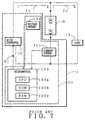
- a battery charging device 1 includes an AC/DC converter 10 (AC/DC converting means) serving as a DC power source, and a full-charging detecting device 11 serving as a full-charging detecting means.
- the full-charging detecting device includes a current sensor 101, a voltage sensor 102 and a microcomputer 103.
- the AC/DC converter 10 converts the AC voltage source from an alternator (not shown) into a DC voltage, and also supplies a charging current Ic to the battery B.
- the charging current Ic is also supplied to the current sensor 101 connected in series with the battery B.
- a discharging current Io discharged from the in-vehicle battery B is supplied to a load 12 and also to the current sensor 101.
- the current sensor 101 detects the charging current Ic supplied to the battery B and the discharging current Io produced therefrom, and supplies the detected values to the microcomputer 103.
- the microcomputer 103 is also supplied with the detected value of the terminal voltage across the battery B (hereinafter referred to as a terminal voltage VB) which is detected by the voltage sensor 102 connected in parallel to the in-vehicle battery B.
- the microcomputer 103 includes a CPU 103a which is operated in accordance with a prescribed control program, an ROM 103b which stores the control program for the CPU 103a and a prescribed full-charging level, and a RAM 103c which temporarily stores the data necessary to perform the computation in the CPU 103a.
- the CPU 103a successively detects the remaining capacity of the in vehicle battery B by the above accumulation system. When the detected remaining capacity exceeds the prescribed full-charged capacity held in the ROM 103b, the CPU 103a detects that the battery B has reached the full-charged state, and supplies a charging stopping signal S1 to the AC/DC converter 10. At this time, the AC/DC converter 10 stops supply of the charging current Ic to the battery B. In short, when the in-vehicle battery B reaches the full-charged state, the AC/DC converter 10 stops to supply the charging current. Thus, the degradation of the battery B due to excess charging can be prevented.
- the in-vehicle battery has a characteristic that it will gradually suffers degradation while the charging/discharging therefor is repeated.
- a Ni-family battery that has been generally used as a battery for an electric vehicle has a great change in the full-charging capacity due to the degradation.
- the charging/discharging circuit incorporating the conventional battery charging device detects the full-charged state of the battery and simultaneously stops the charging. Therefore, if the actual full-charging capacity of the battery lowers owing to the degradation, the prescribed full-charging capacity becomes larger than the actual full-charging capacity so that the full-charged state of the battery cannot be detected accurately. As a result, when the battery suffers degradation, although the battery has already been fallen in the full-charged state, the remaining capacity in the full-charged sate does not exceed the prescribed full-charging capacity and the charging for the battery is continued. This leads to further degradation of the battery.
- the full-charging capacity of the battery changes with a change in the battery temperature. Specifically, as the battery temperature falls, the full-charging capacity decreases, whereas as the battery temperature rises, the full-charging capacity increases. Therefore, in the conventional battery charging apparatus, the actual full-charging capacity changes according to the battery temperature and hence becomes different from the prescribed full-charging capacity so that the full-charged state of the battery cannot be detected accurately.
- the actual full-charging capacity increases with a rise in the battery temperature.
- the remaining capacity exceeds the prescribed full-charging capacity.
- the charging for the battery is stopped since the prescribed full-charging capacity ⁇ actual full-charging capacity).
- the actual full-charging capacity decreases with a fall in the battery temperature.
- the remaining capacity does not exceed the prescribed full-charging capacity.
- the charging for the battery is continued by the DC power source since the prescribed full-charging capacity > actual full-charging capacity. This promotes the degradation of the battery.
- the full-charging capacity changes with both the progress of degradation and the temperature of the battery. Therefore, in order to compensate for such changes, it is necessary to measure the using period of the battery and the temperature thereof and acquire the full-charging capacity on the basis of these measured values. This requires complicated control and computation.
- a first object of the invention is to provide a battery charging apparatus which can accurately detect the full-charged state of a battery when it changes owing to degradation of the battery and a method for accurately detecting the full-charged state of the battery using this apparatus.
- a first object of the invention is to provide a battery charging apparatus which can accurately detect the full-charged state of a battery when it changes owing to degradation and temperature change of the battery and a method for accurately detecting the full-charged state of the battery using this apparatus.
- a battery charging apparatus including full-charging detecting means 11 for detecting a full-charged state of a battery B, wherein the full-charging detecting means comprises: charging current detecting means 101 for detecting a charging current supplied from a DC power source 10 while the battery is charged with a constant voltage; and internal-impedance computing means 105a-1 for computing an internal impedance on the basis of a charging voltage of the DC power source and the charging current detected by the charging current detecting means, wherein the internal impedance computed by the internal impedance computing means is compared with a prescribed value to detect the full-charged state.
- the internal impedance does not change dependently on its degradation. Therefore, by comparing the internal impedance and the prescribed value, the full-charged state of the battery can be precisely detected even when the full-charging capacity changes dependently of the degradation of the battery.
- the prescribed value is smaller than the internal impedance when the battery has been fully charged, and the full-charging detecting means detects the full-charging when the computed internal impedance exceeds the prescribed value.
- the prescribed value is set at a value equal to the internal impedance of the battery, and the full-charging detecting means detects the full-charging when the computed internal impedance is equal to the prescribed value.
- the full-charging may be detected when the computed internal impedance is equal to the prescribed value so that the full-charging can be detected in the state more close to the full-charged state.
- a battery charging apparatus including full-charging detecting means for detecting a full-charged state of a battery, wherein the full-charging detecting means comprises: charging current detecting means for detecting a charging current supplied from a DC power source while the battery is charged with a constant voltage; and internal-impedance computing means for sequentially computing an internal impedance on the basis of a charging voltage of the DC power source and the charging current detected by the charging current detecting means, wherein the full-charging is detected when there is no variation on the basis of the internal impedance computed by the internal impedance computing means.
- the internal impedance of the battery when it has been fully charged necessarily becomes constant irrespectively of the degradation or the temperature of the in-vehicle battery. Therefore, the full-charging is detected when there is no variation in the internal impedance of the battery on the basis of the internal impedance of the battery sequentially computed by the internal impedance computing means. Thus, even when the full-charging capacity varies owing to the degradation or temperature change of the battery, the full-charged state of the battery can be detected precisely.
- the battery charging apparatus further comprises charging stopping means for stopping supply of the charging current to the battery when the full-charging is detected by the full-charging detecting means.
- charging can be automatically stopped when the battery has been fully charged, thereby preventing excess charging.
- the battery is an in-vehicle battery
- the DC power source is an AC/DC converter for converting an AC current from an alternator into a DC current
- the full-charging detecting means supply of the charging current from the AC/DC converting means to the in-vehicle battery is stopped.
- the battery charging apparatus further comprising:
- a user can know from the warning from the warning generating means that the battery has been fully charged. Therefore, the user stops the charging of the battery to prevent its excess charging.
- a method of detecting full-charging of a battery comprising the steps of: detecting a charging current supplied from a DC power source to a battery while the battery is charged with a constant voltage; computing an internal impedance of the battery on the basis of a charging voltage of the DC power source and the charging current; and comparing the internal impedance with a prescribed value to detect the full-charging of the battery.
- the internal impedance does not change dependently on its degradation. Therefore, by comparing the internal impedance and the prescribed value to detect the full-charging, the full-charged state of the battery can be precisely detected even when the full-charging capacity changes dependently of the degradation of the battery.
- a method of detecting full-charging of a battery comprising the steps of: detecting a charging current supplied from a DC power source to a battery while the battery is charged with a constant voltage; sequentially computing an internal impedance of the battery on the basis of a charging voltage of the DC power source and the charging current; and detecting the full-charging when there is no variation in the internal impedance.
- the internal impedance of the battery when it has been fully charged necessarily becomes constant irrespectively of the degradation or the temperature of the in-vehicle battery. Therefore, the full-charging is detected when there is no variation in the internal impedance of the battery on the basis of the internal impedance of the battery sequentially computed by the internal impedance computing means. Thus, even when the full-charging capacity varies owing to the degradation or temperature change of the battery, the full-charged state of the battery can be detected precisely.
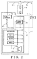
- Fig. 2 is a circuit diagram of an embodiment of the charging/discharging circuit incorporating the battery charging apparatus according to the invention.
- like reference numerals refer to like parts in the conventional apparatus shown in Fig.7.
- a battery charging apparatus 1 includes an AC/DC converter 10 for charging an in-vehicle battery B with a predetermined voltage (hereinafter referred to as a charging voltage Vc) which is approximately equal to the voltage across the in-vehicle battery and a full-charging detecting device 11 serving as a full-charging detecting means.
- the full-charging detecting device 11 includes a current sensor 101 having the same function as that of the conventional charging current detecting means, a microcomputer 105 and a buzzer 106 serving as a warning generating means which indicates that the in-vehicle battery B has been fully charged.
- the microcomputer 105 includes an A/D converting section (not shown) for sequentially capturing the charging current Ic detected by a current sensor 101 and converting it into a digital value of the charging current Ic, a CPU 105a which is operated in accordance with a prescribed control program, an ROM 105b which stores the control program for the CPU 105a and a prescribed full-charging level, and a RAM 105c which temporarily stores the data necessary to perform the computation in the CPU 105a.
- the full-charged state (remaining capacity 100 %) of the in-vehicle battery B is detected on the basis of the internal impedance thus acquired.
- a charging/discharging stopping signal S1 is produced which stops to supply the charging current Ic from an AC/DC converter 10.
- a warning signal S2 is also produced which causes a buzzer 106 to generate warning for notifying the full-charged state of the in-vehicle battery B.
- the degradation of the in-vehicle battery B can be prevented.
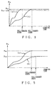
- the internal impedance RB of the in-vehicle battery B has a characteristic changing with passage of time as shown in Fig. 3.
- curve A illustrates a change in the internal impedance RB with a charging time when a degraded in-vehicle battery B is charged with a constant voltage
- curve B illustrates a change in the internal impedance RB with a charging time when a new in-vehicle battery B is charged with a constant voltage.
- the internal impedance RB of the in-vehicle battery B increases with passage of a time.
- the internal impedance does not further increased by charging.
- the internal impedance B1 when the in-vehicle battery has been fully charged does not depend on degradation of the in-vehicle battery B.
- the CPU 105a detects the full-charged state to generate a charging stopping signal S1 for stopping supply of the charging current Ic from the AC/DC converter 10. It should be noted that the prescribed value (RB1 - ⁇ R) is previously stored in the ROM 105b.
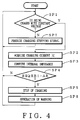
- the CPU 105a determines whether or not the AC/DC converter 10 is being charged with a constant voltage (Step SP1). If YES, the digital value of the charging current Ic detected by the current sensor 101 is taken from the A/D converting section (not shown) (step SP2).
- the CPU 105a serves as a charging stopping means. Namely, it decides that the in-vehicle battery B is in a full-charged state to supply a charging stopping signal S1 to the AC/DC converter 10 (step SP5) and supply a warning generating signal S2 to the buzzer 106 (step SP6).
- the AC/DC converter 10 When the AC/DC converter 10 receives the charging stopping signal S1, it stops supply of the charging current Ic to the in-vehicle battery B to prevent excessive charging therefor. Further, when the buzzer 106 receives the warning generating signal S2, it generates warning sound indicating that the in-vehicle battery B has been fallen in the full-charged state. A user can decide from the warning sound that supply of the charging current to the in-vehicle battery B has been stopped not because the AC/DC converter 10 has suffered a breakdown but because the battery has been fallen in the full-charged state. Thereafter, the processing by the CPU 105a returns to step SP1.
- step SP1 the CPU 105a determines that the battery B is being discharged and not in the full-charged state. If the charging stopping signal S1 is being generated, the CPU 105a stops its supply (step SP7). The processing returns to step SP1.
- the internal impedance RB1 of the in-vehicle battery B when it is in the full-charged state does not change dependently on its degradation. Therefore, by comparing the internal impedance RB and the prescribed value (RB1 - ⁇ R) to detect the full-charging, the full-charged state of the battery can be precisely detected even when the full-charging capacity changes dependently of the degradation of the in-vehicle battery B.
- the in-vehicle battery B e.g. the in-vehicle battery is charged with a constant voltage (1.3 times or more) that is sufficiently higher than the voltage across the battery B.
- the full-charging should be detected when the internal impedance RB computed by the CPU 105a exceeds (RB1 - ⁇ R). In such a manner, as long as the internal impedance when the battery has been actually fully charged varies in a range smaller than the prescribed value (RB1 - ⁇ R) owing to a change in the battery temperature, the full-charging state can be surely detected.
- the battery charging apparatus can be suitably used in an atmosphere where the temperature is stable and hence the battery temperature does not vary so greatly.
- the internal impedance RB of the in-vehicle battery B has a characteristic depending on the battery temperature as shown in Fig. 5.
- the internal impedance RB of the battery at the normal temperature increases in a second-order function with passage of the charging time.
- a prescribed value RB1 is maintained even when the charging is continued.
- the internal impedance RB of the battery at the low temperature also increases in the second-order function with passage of the charging time.
- a prescribed value RB2 that is lower than the prescribed value RB1 is maintained.
- the microcomputer 105 sequentially acquires the internal impedance RB of the in-vehicle battery B.
- the microcomputer 105 detects that a change ⁇ RB in the internal impedance thus acquired is not larger than a prescribed value and hence the internal impedance does not vary, it detects that the in-vehicle battery B has been fully charged, and issues a charging stopping signal S1 stopping supply of the charging current Ic from the AC/DC converter 10.
- the battery charging apparatus has the same configuration as that according to the first embodiment.
- Fig. 6 illustrates the operation of the CPU 105a in this embodiment. Referring to the flowchart of Fig. 6, an explanation will be given of the operation of the charging/discharging circuit incorporating the battery charging apparatus according to the second embodiment.
- like reference symbols refer to like steps in the first embodiment.
- the CPU 105a operates in steps SP1 to SP3 in the same manner as the first embodiment.
- step SP8 the CPU 105a subtracts the internal impedance RB in step SP3 acquired in step SP3 from the internal impedance RB acquired in the previous time, thereby computing the change ⁇ RB in the internal impedance RB (step SP8).
- step SP9 the CPU 105a determines that the in-vehicle battery B has been fully charged so that the internal impedance RB has become stable (Y in step SP9). The processing proceeds to step SP5. If the change ⁇ RB is larger than the prescribed value (N in step SP8), the CPU 105a determines that the in-vehicle battery is not in the full-charged state. The processing returns to step SP1.
- the microcomputer 105 sequentially acquire the internal impedance RB of the in-vehicle battery B.
- the microcomputer 105 detects that a change ⁇ RB in the internal impedance thus acquired is not larger than a prescribed value and hence the internal impedance does not vary, it detects that the in-vehicle battery B has been fully charged.
- the in-vehicle battery B when its degradation proceeds owing to excess charging to decrease the full-charging capacity, the battery is likely to be discharged. This interferes with the running of the vehicle. In order to obviate this, difficulty, as described above, when the full-charging is detected, the supply of the charging current for the in-vehicle battery is stopped automatically. This prevents the degradation of the in-vehicle battery due to excess charging to assure the running of the vehicle.
- the battery charging apparatus 1 was provided for the in-vehicle battery B.
- the battery charging apparatus 1 may be provided for the other chargeable/dischargeable battery than the in-vehicle battery B to provide the same effect as described above.
- a user can stop the supply of the charging current Ic from the AC/DC converter (DC power source) to the battery, when the full-charging of the battery is detected, it is not required to stop automatically the charging from the AC/DC converter, but only required to issue warning sound informing the user of the full-charged state.
- the user can stop the supply of the charging current IC to the battery, thereby preventing the degradation of the battery due to the excess charging.
- the battery charging apparatus effects the constant-current charging when the remaining capacity is less, and effects the constant-voltage charging when the remaining capacity is more.
- the flowchart of Figs. 4 and 6 can be started.
Landscapes
- Engineering & Computer Science (AREA)
- Power Engineering (AREA)
- Physics & Mathematics (AREA)
- General Physics & Mathematics (AREA)
- Charge And Discharge Circuits For Batteries Or The Like (AREA)
- Secondary Cells (AREA)
- Tests Of Electric Status Of Batteries (AREA)
Abstract
Description
On the other hand, while the in-vehicle battery B is discharged, a discharging current Io discharged from the in-vehicle battery B is supplied to a load 12 and also to the
Claims (12)
- A battery charging apparatus including full-charging detecting means for detecting a full-charged state of a battery, wherein said full-charging detecting means comprises:charging current detecting means for detecting a charging current supplied from a DC power source while the battery is charged with a constant voltage; andinternal-impedance computing means for computing an internal impedance on the basis of a charging voltage of the DC power source and said charging current detected by said charging current detecting means,
wherein the internal impedance computed by said internal impedance computing means is compared with a prescribed value to detect the full-charged state. - A battery charging apparatus according to claim 1, wherein said prescribed value is smaller than the internal impedance when the battery has been fully charged, and said full-charging detecting means detects the full-charging when the computed internal impedance exceeds the prescribed value.
- A battery charging apparatus according to claim 1, wherein where the battery is subjected to boost charging with a constant voltage that is higher than a voltage across the battery, said prescribed value is set at a value equal to the internal impedance of said battery, and said full-charging detecting means detects the full-charging when the computed internal impedance is equal to said prescribed value.
- A battery charging apparatus including full-charging detecting means for detecting a full-charged state of a battery, wherein said full-charging detecting means comprises:charging current detecting means for detecting a charging current supplied from a DC power source while the battery is charged with a constant voltage; andinternal-impedance computing means for sequentially computing an internal impedance on the basis of a charging voltage of the DC power source and said charging current detected by said charging current detecting means,
wherein the full-charging is detected when there is no variation on the basis of the internal impedance computed by said internal impedance computing means. - A battery charging apparatus according to claim 1, further comprising:charging stopping means for stopping supply of the charging current from said battery to the battery when the full-charging is detected by said full-charging detecting means.
- A battery charging apparatus according to claim 4, further comprising:charging stopping means for stopping supply of the charging current from said battery to the battery when the full-charging is detected by said full-charging detecting means.
- A battery charging apparatus according to claim 1, wherein said battery is an in-vehicle battery, said DC power source is an AC/DC converter for converting an AC current from an alternator into a DC current, and when the full-charging is detected by said full-charging detecting means, supply of the charging current from said AC/DC converting means to said in-vehicle battery is stopped.
- A battery charging apparatus according to claim 1, wherein said battery is an in-vehicle battery, said DC power source is an AC/DC converter for converting an AC current from an alternator into a DC current, and when the full-charging is detected by said full-charging detecting means, supply of the charging current from said AC/DC converting means to said in-vehicle battery is stopped.
- A battery charging apparatus according to claim 1, further comprising:warning generating means for generating warning when the full-charging is detected.
- A battery charging apparatus according to claim 4, further comprising:warning generating means for generating warning when the full-charging is detected.
- A method of detecting full-charging of a battery comprising the steps of:detecting a charging current supplied from a DC power source to a battery while the battery is charged with a constant voltage;computing an internal impedance of the battery on the basis of a charging voltage of said DC power source and said charging current; andcomparing said internal impedance with a prescribed value to detect the full-charging of the battery.
- A method of detecting full-charging of a battery comprising the steps of:detecting a charging current supplied from a DC power source to a battery while the battery is charged with a constant voltage;sequentially computing an internal impedance of the battery on the basis of a charging voltage of said DC power source and said charging current; anddetecting the full-charging when there is no variation in said internal impedance.
Applications Claiming Priority (2)
| Application Number | Priority Date | Filing Date | Title |
|---|---|---|---|
| JP18997699A JP3687726B2 (en) | 1999-07-05 | 1999-07-05 | Battery charging device and full charge detection method |
| JP18997699 | 1999-07-05 |
Publications (2)
| Publication Number | Publication Date |
|---|---|
| EP1067652A2 true EP1067652A2 (en) | 2001-01-10 |
| EP1067652A3 EP1067652A3 (en) | 2002-04-10 |
Family
ID=16250333
Family Applications (1)
| Application Number | Title | Priority Date | Filing Date |
|---|---|---|---|
| EP00114330A Withdrawn EP1067652A3 (en) | 1999-07-05 | 2000-07-04 | Battery charging apparatus and full-charging detecting method |
Country Status (3)
| Country | Link |
|---|---|
| US (1) | US6232746B1 (en) |
| EP (1) | EP1067652A3 (en) |
| JP (1) | JP3687726B2 (en) |
Cited By (1)
| Publication number | Priority date | Publication date | Assignee | Title |
|---|---|---|---|---|
| GB2448412A (en) * | 2007-04-10 | 2008-10-15 | Sanyo Electric Co | Battery full charge capacity detection |
Families Citing this family (10)
| Publication number | Priority date | Publication date | Assignee | Title |
|---|---|---|---|---|
| JP3720290B2 (en) * | 2001-10-04 | 2005-11-24 | 矢崎総業株式会社 | Battery charging efficiency detection method and apparatus, battery charge electricity amount detection method and apparatus |
| JP5092218B2 (en) * | 2005-09-06 | 2012-12-05 | 富士通株式会社 | Abnormality detection method for battery pack, battery pack and electronic device |
| JP4925108B2 (en) * | 2007-01-10 | 2012-04-25 | ヤマハモーターパワープロダクツ株式会社 | Electric golf cart |
| JP5268085B2 (en) * | 2007-01-10 | 2013-08-21 | ヤマハモーターパワープロダクツ株式会社 | Battery capacity management device |
| US8441230B2 (en) * | 2008-09-08 | 2013-05-14 | Techtronic Power Tools Technology Limited | Battery charger |
| JP2011017619A (en) * | 2009-07-09 | 2011-01-27 | Mitsumi Electric Co Ltd | Battery pack, semiconductor device, portable device, notification method, and notification program |
| US9350184B2 (en) | 2012-05-24 | 2016-05-24 | Thomson Licensing | Method and apparatus for displaying battery status |
| FR3025889B1 (en) * | 2014-09-12 | 2016-11-18 | Commissariat Energie Atomique | MANAGING THE RECHARGE OF THE BATTERY OF AN ELECTRIC VEHICLE |
| JP6409746B2 (en) * | 2015-11-16 | 2018-10-24 | トヨタ自動車株式会社 | Battery charging system |
| US11498446B2 (en) * | 2020-01-06 | 2022-11-15 | Ford Global Technologies, Llc | Plug-in charge current management for battery model-based online learning |
Family Cites Families (10)
| Publication number | Priority date | Publication date | Assignee | Title |
|---|---|---|---|---|
| US3816807A (en) * | 1973-07-18 | 1974-06-11 | Gen Electric | Impedance controlled battery charger and method of charging with monitoring of a.c. answer signal |
| US5193067A (en) * | 1988-12-05 | 1993-03-09 | Nippondenso Co., Ltd. | Battery condition detecton apparatus |
| EP0593196A3 (en) * | 1992-10-13 | 1994-12-28 | Gnb Battery Tech Inc | Method for optimizing the charge of lead-acid batteries and interactive charger. |
| US5642031A (en) * | 1994-02-28 | 1997-06-24 | Black & Decker Inc. | Battery recharging system with state of charge detection that initially detects whether a battery to be charged is already at or near full charge to prevent overcharging |
| US5574355A (en) * | 1995-03-17 | 1996-11-12 | Midtronics, Inc. | Method and apparatus for detection and control of thermal runaway in a battery under charge |
| JP3327084B2 (en) * | 1995-12-08 | 2002-09-24 | 松下電器産業株式会社 | Internal combustion engine speed measurement device |
| WO1997032384A1 (en) * | 1996-02-27 | 1997-09-04 | Advanced Charger Technology, Inc. | Method and apparatus for charging a battery |
| US5828201A (en) * | 1997-10-30 | 1998-10-27 | Lockheed Martin Corporation | Method for maintaining the charge capacity of traction battery modules of a hybrid electric vehicle |
| US6144838A (en) * | 1997-12-19 | 2000-11-07 | Educational Testing Services | Tree-based approach to proficiency scaling and diagnostic assessment |
| US6072299A (en) * | 1998-01-26 | 2000-06-06 | Medtronic Physio-Control Manufacturing Corp. | Smart battery with maintenance and testing functions |
-
1999
- 1999-07-05 JP JP18997699A patent/JP3687726B2/en not_active Expired - Fee Related
-
2000
- 2000-07-04 EP EP00114330A patent/EP1067652A3/en not_active Withdrawn
- 2000-07-05 US US09/610,366 patent/US6232746B1/en not_active Expired - Fee Related
Cited By (3)
| Publication number | Priority date | Publication date | Assignee | Title |
|---|---|---|---|---|
| GB2448412A (en) * | 2007-04-10 | 2008-10-15 | Sanyo Electric Co | Battery full charge capacity detection |
| GB2448412B (en) * | 2007-04-10 | 2010-04-07 | Sanyo Electric Co | Fully-charged battery capacity detection method |
| US7974796B2 (en) | 2007-04-10 | 2011-07-05 | Sanyo Electric Co., Ltd. | Fully-charged battery capacity detection method |
Also Published As
| Publication number | Publication date |
|---|---|
| EP1067652A3 (en) | 2002-04-10 |
| JP2001021630A (en) | 2001-01-26 |
| US6232746B1 (en) | 2001-05-15 |
| JP3687726B2 (en) | 2005-08-24 |
Similar Documents
| Publication | Publication Date | Title |
|---|---|---|
| EP0225364B1 (en) | Monitoring state of battery charge | |
| US10712393B2 (en) | Energy storage device management apparatus, energy storage device module, vehicle, and energy storage device management method | |
| US5574355A (en) | Method and apparatus for detection and control of thermal runaway in a battery under charge | |
| US20100156356A1 (en) | Method of quick charging lithium-based secondary battery and electronic device using same | |
| US7541775B2 (en) | Enhanced-accuracy battery capacity prediction using multiple discharge curves | |
| US7944178B2 (en) | Fully-charged battery capacity detection method | |
| US5365453A (en) | System for indicating a low battery condition | |
| US8502504B1 (en) | Model-based battery fuel gauges and methods | |
| US8643331B1 (en) | Enhanced voltage-based fuel gauges and methods | |
| US7683580B2 (en) | Remaining-battery-capacity estimating apparatus, remaining-battery-capacity estimating method, and remaining-battery-capacity estimating computer program | |
| US20120271578A1 (en) | Battery management system | |
| US5723971A (en) | Apparatus for charging a battery for a charge time determined based on the depth of discharge | |
| US8736232B2 (en) | Full charge capacity correction circuit, charging system, battery pack and full charge capacity correction method | |
| US6232746B1 (en) | Battery charging apparatus and full-charging detecting method | |
| JPH0659003A (en) | Remaining capacity meter for battery | |
| JP2000312443A (en) | Module battery control device, module battery unit, and module battery control method | |
| JP3432463B2 (en) | Battery capacity measurement device | |
| JP3225119B2 (en) | Battery life detector | |
| US6420853B1 (en) | Battery charger capable of accurately determining fully charged condition regardless of batteries with different charge chracteristics | |
| US5744939A (en) | Temperature compensation monitoring circuit for a battery pack charging apparatus | |
| EP0613593A1 (en) | Battery management system | |
| JPH09243717A (en) | Battery residual capacity detection method and device | |
| US6462514B2 (en) | Battery unit with an integral charge controller | |
| JPH10174299A (en) | Method and apparatus for calculating charge capacity of storage battery | |
| JP2002325362A (en) | Secondary battery capacity measurement system, secondary battery full capacity compensating method, charging efficiency compensating method and discharge efficiency compensating method |
Legal Events
| Date | Code | Title | Description |
|---|---|---|---|
| PUAI | Public reference made under article 153(3) epc to a published international application that has entered the european phase |
Free format text: ORIGINAL CODE: 0009012 |
|
| AK | Designated contracting states |
Kind code of ref document: A2 Designated state(s): DE FR GB Kind code of ref document: A2 Designated state(s): AT BE CH CY DE DK ES FI FR GB GR IE IT LI LU MC NL PT SE |
|
| AX | Request for extension of the european patent |
Free format text: AL;LT;LV;MK;RO;SI |
|
| PUAL | Search report despatched |
Free format text: ORIGINAL CODE: 0009013 |
|
| AK | Designated contracting states |
Kind code of ref document: A3 Designated state(s): AT BE CH CY DE DK ES FI FR GB GR IE IT LI LU MC NL PT SE |
|
| AX | Request for extension of the european patent |
Free format text: AL;LT;LV;MK;RO;SI |
|
| 17P | Request for examination filed |
Effective date: 20020611 |
|
| AKX | Designation fees paid |
Free format text: DE FR GB |
|
| RAP1 | Party data changed (applicant data changed or rights of an application transferred) |
Owner name: YAZAKI CORPORATION |
|
| 17Q | First examination report despatched |
Effective date: 20080215 |
|
| STAA | Information on the status of an ep patent application or granted ep patent |
Free format text: STATUS: THE APPLICATION IS DEEMED TO BE WITHDRAWN |
|
| 18D | Application deemed to be withdrawn |
Effective date: 20080626 |