EP1067635A2 - Electrical connector assembly with guide pin latching system - Google Patents
Electrical connector assembly with guide pin latching system Download PDFInfo
- Publication number
- EP1067635A2 EP1067635A2 EP00113841A EP00113841A EP1067635A2 EP 1067635 A2 EP1067635 A2 EP 1067635A2 EP 00113841 A EP00113841 A EP 00113841A EP 00113841 A EP00113841 A EP 00113841A EP 1067635 A2 EP1067635 A2 EP 1067635A2
- Authority
- EP
- European Patent Office
- Prior art keywords
- latch
- housing
- connectors
- connector
- electrical connector
- Prior art date
- Legal status (The legal status is an assumption and is not a legal conclusion. Google has not performed a legal analysis and makes no representation as to the accuracy of the status listed.)
- Withdrawn
Links
Images


Classifications
-
- H—ELECTRICITY
- H01—ELECTRIC ELEMENTS
- H01R—ELECTRICALLY-CONDUCTIVE CONNECTIONS; STRUCTURAL ASSOCIATIONS OF A PLURALITY OF MUTUALLY-INSULATED ELECTRICAL CONNECTING ELEMENTS; COUPLING DEVICES; CURRENT COLLECTORS
- H01R13/00—Details of coupling devices of the kinds covered by groups H01R12/70 or H01R24/00 - H01R33/00
- H01R13/62—Means for facilitating engagement or disengagement of coupling parts or for holding them in engagement
- H01R13/627—Snap or like fastening
- H01R13/6275—Latching arms not integral with the housing
-
- H—ELECTRICITY
- H01—ELECTRIC ELEMENTS
- H01R—ELECTRICALLY-CONDUCTIVE CONNECTIONS; STRUCTURAL ASSOCIATIONS OF A PLURALITY OF MUTUALLY-INSULATED ELECTRICAL CONNECTING ELEMENTS; COUPLING DEVICES; CURRENT COLLECTORS
- H01R13/00—Details of coupling devices of the kinds covered by groups H01R12/70 or H01R24/00 - H01R33/00
- H01R13/40—Securing contact members in or to a base or case; Insulating of contact members
- H01R13/42—Securing in a demountable manner
- H01R13/436—Securing a plurality of contact members by one locking piece or operation
-
- H—ELECTRICITY
- H01—ELECTRIC ELEMENTS
- H01R—ELECTRICALLY-CONDUCTIVE CONNECTIONS; STRUCTURAL ASSOCIATIONS OF A PLURALITY OF MUTUALLY-INSULATED ELECTRICAL CONNECTING ELEMENTS; COUPLING DEVICES; CURRENT COLLECTORS
- H01R13/00—Details of coupling devices of the kinds covered by groups H01R12/70 or H01R24/00 - H01R33/00
- H01R13/62—Means for facilitating engagement or disengagement of coupling parts or for holding them in engagement
- H01R13/629—Additional means for facilitating engagement or disengagement of coupling parts, e.g. aligning or guiding means, levers, gas pressure electrical locking indicators, manufacturing tolerances
-
- Y—GENERAL TAGGING OF NEW TECHNOLOGICAL DEVELOPMENTS; GENERAL TAGGING OF CROSS-SECTIONAL TECHNOLOGIES SPANNING OVER SEVERAL SECTIONS OF THE IPC; TECHNICAL SUBJECTS COVERED BY FORMER USPC CROSS-REFERENCE ART COLLECTIONS [XRACs] AND DIGESTS
- Y10—TECHNICAL SUBJECTS COVERED BY FORMER USPC
- Y10S—TECHNICAL SUBJECTS COVERED BY FORMER USPC CROSS-REFERENCE ART COLLECTIONS [XRACs] AND DIGESTS
- Y10S439/00—Electrical connectors
- Y10S439/953—Electrical connectors with latch rod to be retainingly received by opening of mating connector
Definitions
- This invention generally relates to the art of electrical connectors and, particularly, to an electrical connector assembly which includes guide pins that perform a dual function of guiding a pair of connectors into mated condition as well as latching the connectors in the mated condition.
- a typical electrical connector assembly includes a pair of electrical connectors which interconnect respective conductive terminals when the connectors are mated.
- extraneous latching mechanisms are provided to hold the connectors in mated condition and to prevent the connectors from pulling apart.
- latching mechanisms require space or occupy an area of the connectors. In some instances, this space can be considerable in relation to much smaller terminals of the connectors. If one connector is mounted on a circuit board, a panel or the like, the space required for the latching mechanisms can occupy valuable "real estate" on the board or panel.
- one connector of a connector assembly may include one or more guide holes for receiving complementary guide pins projecting from the mating connector.
- guiding mechanisms require space or occupy a considerable area of the connectors.
- the present invention is directed to solving the problems of latching mechanisms and guiding mechanisms taking up excessive space by a unique system wherein one of the connectors of the connector assembly includes at least one guide pin that performs a dual function of not only guiding the connectors into mated condition but to facilitate latching the connectors in the mated condition.
- An object, therefore, of the invention is to provide a new and improved electrical connector assembly of the character described which includes a unique guiding and latching system.
- the electrical connector assembly includes a first connector having a housing mounting a plurality of terminals.
- the housing has a guide hole at a mating face thereof.
- a second connector includes a housing mounting a plurality of terminals for connection to the terminals of the first connector when the connectors are mated.
- a guide pin on the second connector is insertable into the guide hole of the first connector to guide the connectors into mated condition.
- the guide pin has a latch portion.
- a latch member on the first connector is engageable with the latch portion of the guide pin when the connectors are mated to hold the connectors in mated condition. Therefore, the guide pin performs a dual function of guiding the connectors as well as latching the connectors.
- a pair of the guide holes are provide at opposite ends of the mating face of the first connector, along with a pair of guide pins on the second connector.
- Both guide pins have latch portions
- the second connector includes a pair of the latch members.
- the latch portions on the guide pins are provided by notches in the sides thereof.
- the latch members include latch hooks engageable in the notches.
- Each latch member comprises a latch arm pivotable relative to the housing of the first connector.
- the latch arm is a separate member independent of the housing of the first connector.
- the latch arm is pivoted to the housing intermediate opposite ends of the latch arm.
- One end of the latch arm is located inside the housing for engaging the latch notch of a respective one of the guide pins.
- An opposite end of the latch arm is located outside the housing for manual manipulation by an operator.
- the latch arms are fabricated of spring metal material, and the opposite ends of the latch arms include spring portions for biasing the hooked ends of the latch arms into latching condition with the notches of the guide pins.
- an electrical connector assembly generally designated 10, which includes a first or cable connector, generally designated 12, and a second or header connector, generally designated 14.
- Cable connector 12 is provide for terminating a plurality of pairs of electrical wires of a high speed electrical cable 16.
- Header connector 14 includes a pair of externally threaded mounting posts 18 for mounting the header connector on a backplane, panel or the like.
- cable connector 12 mounts a pair of latch members 20 on opposite sides thereof which are operatively associated with a pair of guide pins 22 at opposite ends of header connector 14.
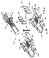
- cable connector 12 includes a housing, generally designated 24, formed by a pair of substantially identical housing halves 26 held together by a plurality of bolts 28 and nuts 30.
- the housing defines a mating face 32.
- the housing halves combines to define an interior cavity 34 having a front opening 34a and a rear opening 34b.
- the housing halves may be fabricated of die-cast metal material or of molded plastic material.
- a boot (not shown) of elastomeric material may cover the housing. The boot may have access openings to the latch members.
- electrical cable 16 includes a plurality of twisted pairs of electrical wires 36 which are terminated to conductive terminals overmolded in a plurality of thin flat wafers 38.
- the wafers are molded of dielectric material such as plastic or the like.
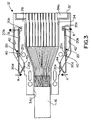
- the wafers are closely juxtaposed in a parallel array and are positioned within interior cavity 34 of one of the housing halves 26 such that cable 16 projects out of rear opening 34b of the cavity as seen in Figure 3.
- the cable and wafer subassembly can be positioned in a bottom one of the housing halves 26 (e.g., the right-hand housing half as viewed in Figure 2) and the other housing half then is positioned on top of the one housing half to completely enclose the cable/wafer subassembly, with bolts 28 and nuts 30 being used to close housing 24 about the cable/wafer subassembly.
- each plastic wafer 38 is overmolded about a plurality of female terminals which are exposed at front opening 34a of cavity 34 of housing 24.
- cable connector 12 mounts a pair of the latch members 20 which were briefly mentioned in describing Figure 1.
- Each latch member is formed by a latch arm stamped and formed of spring sheet metal material.
- Each latch arm is pivoted to housing halves 26 by a rounded pivot portion 20a formed intermediate opposite ends of the latch arm and disposed within rounded pivot cavities 40 in the housing halves.
- One end 20b of each latch arm is located within a cavity 42 of the housing halves and includes an inwardly directed latch hook 20c.
- An opposite end 20d of each latch arm is exposed exteriorly of the housing for manual engagement by an operator. This can be seen clearly in Figure 1.
- the outside or opposite end of each latch arm is bent back inwardly to form a spring portion 20e which is engageable with the housing halves, as at 44.
- guide pins 22 of header connector 14 have latch portions in the form of latch notches 46 in the outside surfaces thereof.
- housing 24 of cable connector 12 has a pair of guide holes 50 for receiving guide pins 22 of the header connector.
- Guide holes 50 communicate with cavities 42 of housing 24 so that latch hooks 20c of latch members 20 can engage within latch notches 46 in the outside surface of guide pins 22.
- Distal ends 22a of the guide pins are chamfered to provide angled surfaces for engaging latch hooks 20c of latch arms 20. This causes the latch hooks to be biased outwardly in the direction of arrows "B" (Fig. 3) until the latch hooks become aligned with latch notches 46 in the guide pins.
- each plastic wafer 38 is overmolded about a plurality of conductive female terminals 52 which receive a plurality of terminal pins 54 of header connector 14.
- the terminal pins are mounted in a housing 55 of the header connector and have terminating ends 54a which can be terminated to a plurality of electrical wires, other terminal devices, conductors on a printed circuit board or a wide variety of other configurations. It should be understood that the concepts of the invention, particularly the use of a dual function guide pin, are not limited to the specific cable connector 12 or header connector 14 disclosed herein.
Landscapes
- Details Of Connecting Devices For Male And Female Coupling (AREA)
Abstract
Description
Claims (16)
- An electrical connector assembly (10), comprising:a first connector (12) including a housing (24) mounting a plurality of terminals (52) and having a guide hole (50) at a mating face (32) of the housing;a second connector (14) including a housing (55) mounting a plurality of terminals (54) for connection to the terminals of the first connector when the connectors are mated, and a guide pin (22) for insertion into the guide hole (50) of the first connector (12) to guide the connectors into mated condition, the guide pin including a latch portion (46); anda latch member (20) on the first connector (12) for engaging the latch portion (46) of the guide pin (22) when the connectors are mated to hold the connectors in mated condition,
whereby the guide pin (22) performs a dual function of guiding the connectors (12,14) as well as latching the connectors. - The electrical connector assembly of claim 1 wherein said latch portion of the guide pin (22) comprises a notch (46) in a side thereof.
- The electrical connector assembly of claim 2 wherein said latch member (20) includes a latch hook (20c) engageable in said notch (46).
- The electrical connector assembly of claim 1, including a pair of said guide holes (50) at opposite ends of the mating face (32) of the first connector (12), along with a pair of guide pins (22) on the second connector (14).
- The electrical connector assembly of claim 4 wherein both of said guide pins (22) have latch portions (46), and including a pair of said latch members (20) on the first connector (12).
- The electrical connector assembly of claim 1 wherein said latch member comprises a latch arm (20) pivotable relative to the housing (24) of the first connector (12).
- The electrical connector assembly of claim 6 wherein said latch arm is a separate member (20) independent of the housing (24) of the first connector (12).
- The electrical connector assembly of claim 7 wherein said latch arm (20) is pivoted to the housing (24) intermediate opposite ends (20b,20d) of the latch arm.
- The electrical connector assembly of claim 8 wherein one end (20b) of the latch arm (20)is located inside the housing (24) for engaging the latch portion (46) of the guide pin (22), and an opposite end (20d) of the latch arm is located outside the housing for manual manipulation by an operator.
- The electrical connector assembly of claim 9 wherein said latch arm (20) is fabricated of spring metal material and the opposite end (20d) of the latch arm includes a spring portion (20e) for biasing the one end (20b) of the latch arm into latching condition with the latch portion (46) of the guide pin (22).
- An electrical connector assembly (10), comprising:a first connector (12) including a housing (24) mounting a plurality of terminals (52) and having a pair of guide holes (50) at opposite ends of a mating face (32) of the housing;a second connector (14) including a housing (55) mounting a plurality of terminals (54) for connection to the terminals of the first connector when the connectors are mated, and a pair of guide pins (22) for insertion into the pair of guide holes (50) of the first connector (12) to guide the connectors into mated condition, the guide pins including latch notches (46) in the sides thereof; anda pair of latch members (20) on the first connector (12), the latch members including latch hooks (20c) engageable in the latch notches (46) of the guide pins (22) when the connectors are mated to hold the connectors in mated condition,
whereby the guide pins (22) perform dual functions of guiding the connectors (12,14) as well as latching the connectors. - The electrical connector assembly of claim 11 wherein each latch member (20) comprises a latch arm pivotable relative to the housing (24) of the first connector (12).
- The electrical connector assembly of claim 12 wherein said latch arm is a separate member (20) independent of the housing (24) of the first connector (12).
- The electrical connector assembly of claim 13 wherein said latch arm (20) is pivoted to the housing (24) intermediate opposite ends (20b,20d) of the latch arm.
- The electrical connector assembly of claim 14 wherein one end (20b) of the latch arm (20) is located inside the housing (24) for engaging the latch portion (46) of the guide pin (22), and an opposite end (20d) of the latch arm is located outside the housing for manual manipulation by an operator.
- The electrical connector assembly of claim 15 wherein said latch arm (20) is fabricated of spring metal material and the opposite end (20d) of the latch arm includes a spring portion (20e) for biasing the one end (20b) of the latch arm into latching condition with the latch portion (46) of the guide pin (22).
Applications Claiming Priority (2)
| Application Number | Priority Date | Filing Date | Title |
|---|---|---|---|
| US350237 | 1999-07-09 | ||
| US09/350,237 US6217364B1 (en) | 1999-07-09 | 1999-07-09 | Electrical connector assembly with guide pin latching system |
Publications (2)
| Publication Number | Publication Date |
|---|---|
| EP1067635A2 true EP1067635A2 (en) | 2001-01-10 |
| EP1067635A3 EP1067635A3 (en) | 2002-04-17 |
Family
ID=23375821
Family Applications (1)
| Application Number | Title | Priority Date | Filing Date |
|---|---|---|---|
| EP00113841A Withdrawn EP1067635A3 (en) | 1999-07-09 | 2000-06-30 | Electrical connector assembly with guide pin latching system |
Country Status (6)
| Country | Link |
|---|---|
| US (1) | US6217364B1 (en) |
| EP (1) | EP1067635A3 (en) |
| JP (2) | JP2001093620A (en) |
| KR (1) | KR100360187B1 (en) |
| CN (1) | CN1190874C (en) |
| TW (1) | TW461616U (en) |
Cited By (3)
| Publication number | Priority date | Publication date | Assignee | Title |
|---|---|---|---|---|
| NL1022225C2 (en) * | 2002-12-20 | 2004-06-22 | Framatome Connectors Int | Cable connector and method for joining a cable and such a cable connector. |
| EP1345293A3 (en) * | 2002-03-16 | 2005-12-07 | PROVERTHA Connectors, Cables & Solutions GmbH | Bus-housing for connecteur with locking mechanism |
| DE102018107031A1 (en) * | 2018-03-23 | 2019-09-26 | Samson Aktiengesellschaft | Mechanical fuse for a connector |
Families Citing this family (44)
| Publication number | Priority date | Publication date | Assignee | Title |
|---|---|---|---|---|
| JP3218707B2 (en) | 1992-07-28 | 2001-10-15 | 豊田工機株式会社 | Confirmation device |
| JP2001176608A (en) * | 1999-12-21 | 2001-06-29 | Tyco Electronics Amp Kk | Electronic connector assembly |
| DE10018351C2 (en) * | 2000-04-13 | 2002-07-04 | Siemens Ag | clamp |
| US6371788B1 (en) * | 2000-05-19 | 2002-04-16 | Molex Incorporated | Wafer connection latching assembly |
| US6726501B2 (en) | 2002-06-21 | 2004-04-27 | Molex Incorporated | Latching system for electrical connectors |
| US6685510B1 (en) | 2002-10-22 | 2004-02-03 | Hon Hai Precision Ind. Co., Ltd. | Electrical cable connector |
| US6743050B1 (en) | 2002-12-10 | 2004-06-01 | Hon Hai Precision Ind. Co., Ltd. | Cable assembly with latch mechanism |
| US6926553B2 (en) * | 2003-06-19 | 2005-08-09 | Hon Hai Precision Ind. Co., Ltd. | Cable assembly with improved grounding means |
| TW565037U (en) * | 2003-01-10 | 2003-12-01 | Benq Corp | Connector |
| US6918774B2 (en) * | 2003-06-18 | 2005-07-19 | Hon Hai Precision Ind. Co., Ltd | Electrical connector having long circuit boards |
| US6857912B2 (en) * | 2003-06-25 | 2005-02-22 | Hon Hai Precision Ind. Co., Ltd | Cable assembly with internal circuit modules |
| US6939174B2 (en) * | 2003-07-01 | 2005-09-06 | Hon Hai Precision Ind. Co., Ltd. | Cable assembly with internal circuit modules |
| US6814620B1 (en) | 2003-07-01 | 2004-11-09 | Hon Hai Precision Ind. Co. Ltd. | Electrical connector |
| US6739910B1 (en) | 2003-07-11 | 2004-05-25 | Hon Hai Precision Ind. Co., Ltd. | Cable assembly with internal circuit modules |
| USD503153S1 (en) * | 2004-01-06 | 2005-03-22 | Belkin Corporation | Cable head |
| TWI238572B (en) * | 2004-05-12 | 2005-08-21 | P Two Ind Inc | Clipping device |
| USD513408S1 (en) | 2004-09-03 | 2006-01-03 | Belkin Corporation | DVI cable head |
| KR100677181B1 (en) * | 2004-12-23 | 2007-02-02 | (주)우주일렉트로닉스 | Plug connector |
| USD519465S1 (en) | 2004-12-31 | 2006-04-25 | Belkin Corporation | Adapter |
| US7147512B2 (en) * | 2005-04-19 | 2006-12-12 | Hon Hai Precision Ind. Co., Ltd. | Connector assembly |
| US7300313B1 (en) | 2006-06-02 | 2007-11-27 | Tyco Electronics Corporation | Electrical connector having staggered contacts |
| US7553188B2 (en) * | 2007-04-05 | 2009-06-30 | Tyco Electronics Corporation | Slide lock panel-mount connector |
| US7462067B1 (en) | 2007-08-08 | 2008-12-09 | Tyco Electronics Corporation | Cable-to-cable panel mount power connector |
| US7914318B2 (en) | 2008-11-25 | 2011-03-29 | GM Global Technology Operations LLC | Electrical connector |
| JP2010177132A (en) * | 2009-01-30 | 2010-08-12 | Hitachi Cable Ltd | Latch structure and cable with connector |
| CN201498780U (en) * | 2009-06-26 | 2010-06-02 | 富士康(昆山)电脑接插件有限公司 | Cable Connector Assembly |
| CN102842813B (en) * | 2011-06-20 | 2015-02-04 | 富士康(昆山)电脑接插件有限公司 | Electric connector and butting connector |
| US8794991B2 (en) | 2011-08-12 | 2014-08-05 | Fci Americas Technology Llc | Electrical connector including guidance and latch assembly |
| US9249970B1 (en) | 2012-04-16 | 2016-02-02 | RRK Starlight Enterprises, LLC | Illuminated microphone stand |
| TWI520451B (en) * | 2013-09-27 | 2016-02-01 | 傳承光電股份有限公司 | Connector |
| CN104300276A (en) * | 2013-12-05 | 2015-01-21 | 中航光电科技股份有限公司 | Electric connector |
| CN105273901A (en) * | 2014-05-27 | 2016-01-27 | 徐小芹 | Production method of lotus seed wine |
| US20160126670A1 (en) * | 2014-10-31 | 2016-05-05 | Avago Technologies General Ip (Singapore) Pte. Ltd. | Optical transceiver module and assembly having a latching/delatching mechanism that works with symmetric and asymmetric cage latches |
| CN108155515A (en) * | 2017-12-21 | 2018-06-12 | 上海航天科工电器研究院有限公司 | A kind of lock sheet locks the connector of anti-rock structure soon |
| KR101982985B1 (en) | 2018-10-05 | 2019-05-27 | 기창남 | Sliding drawer type electric oven |
| CN110429433A (en) * | 2019-08-23 | 2019-11-08 | 迈特通信设备(苏州)有限公司 | A kind of guiding device of guide connector grafting |
| TWI729616B (en) * | 2019-12-10 | 2021-06-01 | 台達電子工業股份有限公司 | Power plug |
| USD957352S1 (en) * | 2020-06-30 | 2022-07-12 | Bfly Operations, Inc. | Strain relief |
| USD957351S1 (en) * | 2020-06-30 | 2022-07-12 | Bfly Operations, Inc. | Strain relief |
| US12176650B2 (en) * | 2021-05-05 | 2024-12-24 | Amphenol East Asia Limited (Hong Kong) | Electrical connector with guiding structure and mating groove and method of connecting electrical connector |
| CN113285304B (en) * | 2021-05-27 | 2022-06-17 | 东莞市久宽精密五金电子有限公司 | Wire harness connection port is provided with anchor clamps fixing device |
| KR102703590B1 (en) * | 2022-01-03 | 2024-09-05 | 엘아이지넥스원 주식회사 | Connector Accessory and connector including the same |
| DE102022101805B3 (en) | 2022-01-26 | 2023-02-09 | HARTING Electronics GmbH | Connectors, in particular D-Sub connectors |
| JP7729262B2 (en) * | 2022-05-20 | 2025-08-26 | トヨタ自動車株式会社 | Charging mechanism |
Family Cites Families (16)
| Publication number | Priority date | Publication date | Assignee | Title |
|---|---|---|---|---|
| US4980800A (en) * | 1989-09-27 | 1990-12-25 | Sun Microsystems, Inc. | Electronic unit retention system |
| US5154629A (en) * | 1990-08-08 | 1992-10-13 | Icontec, Inc. | Energy transmission cable connector with latching mechanism |
| US5197900A (en) * | 1990-12-21 | 1993-03-30 | Icontec, Inc. | Energy transmission cable connector with interchangeable locking mechanisms |
| EP0512438B1 (en) * | 1991-05-09 | 1999-09-08 | Molex Incorporated | Electrical connector assemblies |
| US5194020A (en) | 1991-06-17 | 1993-03-16 | W. L. Gore & Associates, Inc. | High-density coaxial interconnect system |
| US5201669A (en) * | 1991-09-16 | 1993-04-13 | Advanced-Connectek Inc. | Connection device of a computer connection |
| US5167523A (en) * | 1991-11-01 | 1992-12-01 | Harbor Electronics, Inc. | Electrical connector |
| US5190472A (en) | 1992-03-24 | 1993-03-02 | W. L. Gore & Associates, Inc. | Miniaturized high-density coaxial connector system with staggered grouper modules |
| US5380216A (en) | 1992-05-11 | 1995-01-10 | The Whitaker Corporation | Cable backpanel interconnection |
| DE9311781U1 (en) | 1992-10-29 | 1993-09-30 | Siemens AG, 80333 München | Cable connector for multi-core cables |
| DE69218223T2 (en) | 1992-12-02 | 1997-06-26 | Molex Inc | Electrical connector system |
| US5364292A (en) * | 1993-12-15 | 1994-11-15 | Itt Corporation | Cable harness assembly for IC card |
| JPH07272794A (en) * | 1994-03-31 | 1995-10-20 | Mitsubishi Electric Corp | Connector device |
| DE4425466A1 (en) | 1994-07-19 | 1996-01-25 | Thomas & Betts Gmbh | Cable connectors |
| EP0760542B1 (en) | 1995-08-26 | 2002-02-27 | Molex Incorporated | Electrical connector with improved latching system |
| US5823812A (en) * | 1996-08-08 | 1998-10-20 | Symbol Technologies, Inc. | Electrical connector |
-
1999
- 1999-07-09 US US09/350,237 patent/US6217364B1/en not_active Expired - Lifetime
-
2000
- 2000-06-30 EP EP00113841A patent/EP1067635A3/en not_active Withdrawn
- 2000-07-03 JP JP2000239192A patent/JP2001093620A/en active Pending
- 2000-07-07 TW TW089211774U patent/TW461616U/en not_active IP Right Cessation
- 2000-07-08 CN CNB001227254A patent/CN1190874C/en not_active Expired - Fee Related
- 2000-07-08 KR KR1020000039045A patent/KR100360187B1/en not_active Expired - Fee Related
-
2003
- 2003-08-26 JP JP2003004405U patent/JP3100036U/en not_active Expired - Lifetime
Cited By (5)
| Publication number | Priority date | Publication date | Assignee | Title |
|---|---|---|---|---|
| EP1345293A3 (en) * | 2002-03-16 | 2005-12-07 | PROVERTHA Connectors, Cables & Solutions GmbH | Bus-housing for connecteur with locking mechanism |
| NL1022225C2 (en) * | 2002-12-20 | 2004-06-22 | Framatome Connectors Int | Cable connector and method for joining a cable and such a cable connector. |
| WO2004057707A1 (en) * | 2002-12-20 | 2004-07-08 | Fci | Cable connector and method of assembling a cable to such a cable connector |
| US7285017B2 (en) | 2002-12-20 | 2007-10-23 | Fci | Cable connector and method of assembling a cable to such a cable connector |
| DE102018107031A1 (en) * | 2018-03-23 | 2019-09-26 | Samson Aktiengesellschaft | Mechanical fuse for a connector |
Also Published As
| Publication number | Publication date |
|---|---|
| CN1280403A (en) | 2001-01-17 |
| CN1190874C (en) | 2005-02-23 |
| KR100360187B1 (en) | 2002-11-09 |
| US6217364B1 (en) | 2001-04-17 |
| EP1067635A3 (en) | 2002-04-17 |
| JP2001093620A (en) | 2001-04-06 |
| KR20010015240A (en) | 2001-02-26 |
| JP3100036U (en) | 2004-04-30 |
| TW461616U (en) | 2001-10-21 |
Similar Documents
| Publication | Publication Date | Title |
|---|---|---|
| US6217364B1 (en) | Electrical connector assembly with guide pin latching system | |
| US5779495A (en) | Electrical connector with improved latching system | |
| US5938458A (en) | Lever type electrical connector | |
| EP1026785B1 (en) | Adapter frame assembly for electrical connectors | |
| US6935893B1 (en) | Electrical connector with terminal position assurance device | |
| EP1026784B1 (en) | Shielded electrical connector | |
| EP0734599B1 (en) | Connector assembly for ic card | |
| US5417590A (en) | Plug and socket electrical connector system | |
| US5118306A (en) | Multi-conductor electrical connector | |
| US5273453A (en) | Electrical connector with positive latch | |
| AU2004238478B2 (en) | Modular jack assembly for jack plugs with varying numbers of wires | |
| EP0351083A2 (en) | Electrical connector | |
| US5213534A (en) | Electrical connector assembly for flat flexible cable | |
| EP0928046A1 (en) | Shielded electrical connector assembly | |
| EP1229612A2 (en) | Keying system for electrical connector assemblies | |
| EP1026786A1 (en) | Grounded electrical connector with tail aligner | |
| EP1337006A2 (en) | Flat circuit connector | |
| US5122081A (en) | Electrical power connector | |
| US6726501B2 (en) | Latching system for electrical connectors | |
| US6830485B2 (en) | Electrical connector with a terminal pin stabilizing plate | |
| WO2004112201A9 (en) | Modular jack assembly | |
| US5425654A (en) | Electrical connector assembly with cam lever lock mechanism | |
| EP0115425A2 (en) | Connector assemble having improved internal latching system | |
| US5409396A (en) | Strain relief means in an electrical connector assembly for ribbon cable | |
| US20060246783A1 (en) | Electrical connector assembly |
Legal Events
| Date | Code | Title | Description |
|---|---|---|---|
| PUAI | Public reference made under article 153(3) epc to a published international application that has entered the european phase |
Free format text: ORIGINAL CODE: 0009012 |
|
| AK | Designated contracting states |
Kind code of ref document: A2 Designated state(s): DE FR GB IT NL SE Kind code of ref document: A2 Designated state(s): AT BE CH CY DE DK ES FI FR GB GR IE IT LI LU MC NL PT SE |
|
| AX | Request for extension of the european patent |
Free format text: AL;LT;LV;MK;RO;SI |
|
| PUAL | Search report despatched |
Free format text: ORIGINAL CODE: 0009013 |
|
| AK | Designated contracting states |
Kind code of ref document: A3 Designated state(s): AT BE CH CY DE DK ES FI FR GB GR IE IT LI LU MC NL PT SE |
|
| AX | Request for extension of the european patent |
Free format text: AL;LT;LV;MK;RO;SI |
|
| 17P | Request for examination filed |
Effective date: 20020926 |
|
| AKX | Designation fees paid |
Free format text: DE FR GB IT NL SE |
|
| 17Q | First examination report despatched |
Effective date: 20080204 |
|
| STAA | Information on the status of an ep patent application or granted ep patent |
Free format text: STATUS: THE APPLICATION IS DEEMED TO BE WITHDRAWN |
|
| 18D | Application deemed to be withdrawn |
Effective date: 20100615 |