EP1067624A1 - Antenna control device and antenna control method - Google Patents
Antenna control device and antenna control method Download PDFInfo
- Publication number
- EP1067624A1 EP1067624A1 EP00900342A EP00900342A EP1067624A1 EP 1067624 A1 EP1067624 A1 EP 1067624A1 EP 00900342 A EP00900342 A EP 00900342A EP 00900342 A EP00900342 A EP 00900342A EP 1067624 A1 EP1067624 A1 EP 1067624A1
- Authority
- EP
- European Patent Office
- Prior art keywords
- antenna
- length
- section
- control
- reception level
- Prior art date
- Legal status (The legal status is an assumption and is not a legal conclusion. Google has not performed a legal analysis and makes no representation as to the accuracy of the status listed.)
- Withdrawn
Links
Images




Classifications
-
- H—ELECTRICITY
- H01—ELECTRIC ELEMENTS
- H01Q—ANTENNAS, i.e. RADIO AERIALS
- H01Q1/00—Details of, or arrangements associated with, antennas
- H01Q1/08—Means for collapsing antennas or parts thereof
- H01Q1/10—Telescopic elements
-
- H—ELECTRICITY
- H01—ELECTRIC ELEMENTS
- H01Q—ANTENNAS, i.e. RADIO AERIALS
- H01Q1/00—Details of, or arrangements associated with, antennas
- H01Q1/12—Supports; Mounting means
- H01Q1/22—Supports; Mounting means by structural association with other equipment or articles
- H01Q1/24—Supports; Mounting means by structural association with other equipment or articles with receiving set
- H01Q1/241—Supports; Mounting means by structural association with other equipment or articles with receiving set used in mobile communications, e.g. GSM
- H01Q1/242—Supports; Mounting means by structural association with other equipment or articles with receiving set used in mobile communications, e.g. GSM specially adapted for hand-held use
- H01Q1/243—Supports; Mounting means by structural association with other equipment or articles with receiving set used in mobile communications, e.g. GSM specially adapted for hand-held use with built-in antennas
- H01Q1/244—Supports; Mounting means by structural association with other equipment or articles with receiving set used in mobile communications, e.g. GSM specially adapted for hand-held use with built-in antennas extendable from a housing along a given path
Definitions
- the present invention relates to an apparatus and method for antenna control of a portable terminal apparatus communicating various kinds of data including voice and images.
- the antenna length of the conventional portable phone apparatus is manually adjusted by the user or adjusted by the user operating a switch.
- a portable phone apparatus having a structure with the antenna manually extended/contracted by the user there is a possibility that the user breaks the antenna by mistake.
- the present invention provides functions of controlling a drive section that detects the antenna reception condition and extends/contracts the antenna according to the detected reception condition, and adjusting the antenna to an appropriate length according to the reception condition. This allows the user to use the portable terminal apparatus under comfortable reception conditions without the need for intervention by the user.
- FIG.1 is a block diagram showing a configuration of a portable terminal apparatus according to Embodiment 1 of the present invention.
- the "portable terminal apparatus” referred to here is a portable radio communication apparatus.
- the portable terminal apparatus refers to a terminal apparatus of a size that allows the user to carry it by hand and move.
- This portable terminal apparatus receives a radio signal via antenna 101 and sends this reception signal to transmission/reception apparatus 102.
- Transmission/reception apparatus 102 modulates/demodulates and outputs the reception signal sent.
- the signal output from transmission/reception apparatus 102 is input to coding/decoding apparatus 106.
- Coding/decoding apparatus 106 performs coding/decoding processing and error correction processing on the input signal and outputs the signal.
- the signal output from coding/decoding apparatus 106 is sent to microphone/speaker 107.
- the signal sent to microphone/speaker 107 is output as voice from the speaker.
- the voice signal input by the microphone of microphone/speaker 107 is sent to coding/decoding apparatus 106.
- the voice signal sent to coding/decoding apparatus 106 is subjected to coding/decoding processing and error correction processing by coding/decoding apparatus 106 and output.
- the voice signal output from coding/decoding apparatus 106 is input to transmission/reception apparatus 102, modulated/demodulated and transmitted from antenna 101.
- Embodiment 1 is provided with antenna extension/contraction control apparatus 103 that automatically adjusts the length of antenna 101 according to the reception condition.
- the "reception condition” referred to here is a reception level of the signal received by antenna 101.
- the “reception level” referred to here is SIR.
- the “antenna length” referred to here is the length of the antenna exposed from the portable terminal apparatus. This is because antenna 101 of this embodiment is housed in the portable terminal apparatus. By the way, it is also possible to adopt a mode for the antenna in which the antenna itself is extendable. The antenna length in this case indicates the substantial length of the antenna.
- Antenna extension/contraction control apparatus 103 is provided with reception level decision apparatus 105 that decides a reception level according to reception level information sent from transmission/reception apparatus 102 and outputs this reception level decision result.
- antenna extension/contraction control apparatus 103 is also provided with antenna control apparatus 104 that extends/contracts the length of antenna 101 to an appropriate length according to the reception level decision result output from reception level decision apparatus 105.
- Antenna control apparatus 104 adjusts the antenna length driven by an electric driving means such as an electric motor, etc.
- the portable terminal apparatus configured above first decides a reception level of antenna 101 by reception level decision apparatus 105. Then, antenna control apparatus 104 automatically controls the antenna to an appropriate length according to the reception level decision result of reception level decision apparatus 105. This allows the antenna to be automatically adjusted to an appropriate length without the need for the user to manually adjust the antenna length according to the reception condition. Furthermore, by deciding the reception level, this portable terminal apparatus not simply automatically extends/contracts the antenna but also automatically adjusts the antenna to an optimal length.
- this portable terminal apparatus controls the antenna length in such a way that these problems are avoided.
- transmission/reception apparatus 102 When the portable terminal apparatus receives a call start request from a radio base station or when the portable terminal apparatus issues a call start request to the radio base station, transmission/reception apparatus 102 outputs a signal indicating "call request generation" to antenna extension/contraction control apparatus 103. At this time, transmission/reception apparatus 102 outputs the reception level information of the reception signal currently received by antenna 101 to antenna extension/contraction control apparatus 103 successively. Then, antenna extension/contraction control apparatus 103 detects a "call request generation” or "reception condition change" from the signal input from transmission/reception apparatus 102 (ST 201).
- reception level decision apparatus 105 of antenna extension/contraction control apparatus 103 decides whether the current reception level exceeds predetermined threshold A or not (ST 202). In the case where reception level decision apparatus 105 decides that the reception level is not higher than threshold A, reception level decision apparatus 105 further decides whether the length of antenna 101 is a maximum or not (ST 203). Here, in the case where reception level decision apparatus 105 decides that the length of antenna 101 is not a maximum, reception level decision apparatus 105 sends a command for extending antenna 101 to antenna control apparatus 104. Then, antenna control apparatus 104 performs processing of extending antenna 101 (ST 204).
- this portable terminal apparatus when it is predicted that the reception level is low because the antenna length is short, this portable terminal apparatus performs control in such a way that antenna 101 is extended. Thus, this portable terminal apparatus automatically raises the reception level. As a result, this portable terminal apparatus can improve the communication condition without the need for intervention by the user.
- reception level decision apparatus 105 decides that antenna 101 reaches a maximum length in ST 203, the portable terminal apparatus starts a call or continues a call that has already been started (ST 205).
- this portable terminal apparatus does not perform any antenna extending processing if the antenna length is a maximum even if the reception level is low. This makes it possible to avoid an unnecessary process of further extending the antenna, which can no longer be extended. Moreover, not executing such antenna extending processing prevents antenna 101 from receiving an excessive force. This also has an effect of preventing malfunctions of the antenna.
- reception level decision apparatus 105 decides that the current reception level exceeds threshold A in ST 202
- reception level decision apparatus 105 further decides whether the reception level exceeds threshold B (here, suppose threshold B is greater than threshold A) or not (ST 206).
- reception level decision apparatus 105 decides that the reception level is not higher than threshold B in ST 206
- the portable terminal apparatus starts a call, or continues a call that has already been started (ST 205).
- reception level decision apparatus 105 decides whether the reception level is higher than threshold B in ST 206.
- reception level decision apparatus 105 decides whether the length of antenna 101 is a minimum or not (ST 207).
- reception level decision apparatus 105 decides that the length of antenna 101 is not a minimum in ST 207
- antenna control apparatus 104 performs processing of contracting antenna 101 by a predetermined length (ST 208) and the process goes back to ST 206.
- reception level decision apparatus 105 again decides whether the reception level with the contracted antenna length exceeds predetermined threshold B or not.
- the reception level does not exceed threshold B
- the portable terminal apparatus starts a call or continues a call that has already been started (ST 205).
- level decision apparatus 105 decides again that the reception level exceeds predetermined threshold B
- the processes in ST 207 and ST 208 are repeated until the predetermined reception level is reached.
- this portable terminal apparatus controls so that antenna 101 is contracted until the reception level falls below threshold B or the antenna length reaches a minimum. This prevents the reception level from becoming too high, allowing the reception level to be maintained in an optimal condition.
- the process returns to ST 205 and the portable terminal apparatus starts a call or continues a call that has already been started.
- transmission/reception apparatus 102 In the case where this portable terminal apparatus receives a call end request from the radio base station or when this portable terminal apparatus issues a call end request to the radio base station, transmission/reception apparatus 102 outputs a signal indicating a "call end request" to antenna extension/contraction control apparatus 103.
- Antenna extension/contraction control apparatus 103 detects the "call end request" signal from the signal input from transmission/reception apparatus 102 (ST 209). Then, reception level decision apparatus 105 decides whether the length of antenna 101 is a minimum or not (ST 210). In the case where reception level decision apparatus 105 decides that the length of antenna 101 is a minimum in ST 210, the portable terminal apparatus ends the call (ST 211). Moreover, in the case where reception level decision apparatus 105 decides that the length of antenna 101 is not a minimum in ST 210, antenna control apparatus 104 performs processing of contracting the length of antenna 101 (ST 212). Then, it is possible to ensure that the length of antenna 101 is contracted to a minimum by repeating the processing in and after ST 210.
- this portable terminal apparatus automatically contracts the antenna length to a minimum when a call ends, and therefore while the user is not using this portable terminal apparatus, the antenna is always kept to a minimum length. This allows the portable terminal apparatus to prevent the antenna from being damaged without any intervention by the user.
- this Embodiment 1 allows antenna 101 to be automatically adjusted to an appropriate length without the need for the user to pick up the end of antenna 101 by hand or operate an input apparatus such as a switch. This allows this portable terminal apparatus to always receive signals in optimal conditions without any intervention by the user. It is also possible to avoid such a case where sudden deterioration of the reception condition of the portable terminal apparatus during a call prevents the user from using the portable terminal apparatus.
- the portable terminal apparatus of the embodiment above can automatically adjust antenna 101 to an appropriate length. This eliminates the need for the user to check the reception level shown on the display and adjust the length of antenna 101 according to the reception level as in the case of the conventional portable terminal apparatus.
- the portable terminal apparatus of the embodiment above can also prevent antenna 101 from being damaged due to an erroneous operation while the user is manually picking up antenna 101.
- the portable terminal apparatus of the embodiment above also has two reception level thresholds, which prevent the length of antenna 101 from becoming longer than necessary. This prevents the user from, for example, touching other people with antenna 101 in the crowd, causing damage to antenna 101.
- Embodiment 1 describes the portable terminal apparatus as an example, but the present invention is also applicable to a stationary terminal apparatus equipped with an extendable antenna. Moreover, Embodiment 1 describes the portable terminal apparatus that communicates voice as an example, but the present invention is also applicable to a portable terminal apparatus that communicates images or other data.
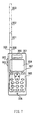
- FIG.3 is a front view and side view of a portable phone apparatus according to Embodiment 2 of the present invention.
- Portable phone apparatus 301 is a portable phone apparatus provided with a capability of switching between an auto extension/contraction mode similar to that in the portable terminal apparatus of Embodiment 1 above and a manual mode that allows the user to adjust the antenna length through button operations.
- the portable phone apparatus is configured by a case 307 in a size that allows the user to carry it by one hand and speak while holding it by one hand.
- Various operation sections, which will be described later, are provided on the surface of case 307.
- various operation sections, which will be described later, are provided inside case 307.
- Input buttons 305 to enter various kinds of information are provided in the lower part of the top face of portable phone apparatus 301.
- a contact sensor is provided beneath input button 305, which sends input information to a control apparatus, which will be described later.
- Display apparatus 304 that displays various kinds of input information of the reception level, etc. of the signal received by antenna 300 and processing content is provided in the upper part of the top face of portable phone apparatus 301.
- speaker 306 that outputs a voice signal sent from another portable phone apparatus is provided in the upper part of the top face of portable phone apparatus 301.
- microphone 308 that inputs a voice signal to be sent to the other portable phone apparatus is provided in the lower part of the top face of portable phone apparatus 301.
- antenna extension/contraction buttons 302 and 303 to extend/contract antenna 300 are provided close to one another in the upper part of the external side of portable phone apparatus 301.
- Antenna extension/contraction button 302 is the button to extend antenna 300.
- Antenna extension/contraction button 303 is the button to contract antenna 300. Providing antenna extension/contraction buttons 302 and 303 at such locations allows the user to operate antenna extension/contraction buttons 302 and 303 while operating input section 305 by one hand. Furthermore, the user can also operate antenna extension/contraction buttons 302 and 303 while speaking.
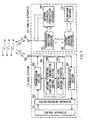
- Portable phone apparatus 301 is provided with transmission/reception apparatus 401 that modulates/demodulates a radio signal sent from another portable phone apparatus and received by antenna 300.
- the modulated/demodulated signal is sent to coding/decoding apparatus 402.
- Coding/decoding apparatus 402 performs coding/decoding processing and error correction processing on the input signal and outputs.
- the signal output from coding/decoding apparatus 402 is sent to control apparatus 403 that carries out control over various processing apparatuses.
- Control apparatus 403 performs predetermined processing on this input signal and outputs it to voice processing apparatus 404.
- Voice processing apparatus 404 performs predetermined processing such as D/A conversion on the input signal and outputs it to speaker 306.
- Speaker 306 outputs the input signal as voice.
- a voice signal input by microphone 308 is sent to voice processing apparatus 404.
- Voice processing apparatus 404 performs predetermined processing such as A/D conversion on the input signal and sends it to control apparatus 403.
- Control apparatus 403 performs predetermined processing on the input signal and sends it to coding/decoding apparatus 402.
- Coding/decoding apparatus 402 performs coding/decoding processing and error correction processing on the input signal and sends it to transmission/reception apparatus 401.
- Transmission/reception apparatus 401 performs modulation/demodulation processing on the input signal and transmits it to the other portable phone apparatus via antenna 300.
- transmission/reception apparatus 401 sends the signal received by antenna 300 to call request detection apparatus 409 provided in control apparatus 403.
- Call request detection apparatus 409 detects a call start requesting signal and a call end requesting signal from the input signal. Then, control section 403 starts or ends a call according to this detection signal.
- call request detection apparatus 409 also detects a call start request signal and a call end request signal from an input signal from input buttons 305.
- transmission/reception apparatus 401 detects the reception level information of the signal received by antenna 300 and outputs it to reception level decision apparatus 408.
- the "reception condition" referred to here is the reception level of the signal received by antenna 300.
- the "reception level” referred to here is SIR.
- Reception level decision apparatus 408 detects the reception level of the signal received by antenna 300 and outputs it to antenna extension/contraction control apparatus 405 provided in control apparatus 403.
- Antenna extension/contraction control apparatus 405 outputs a control signal according to the reception level to antenna drive apparatus 406.
- Antenna drive apparatus 406 extends/contracts antenna 300 driven by an electric driving means such as an electric motor, etc. according to this control signal.
- control apparatus 403 receives various input signals from input buttons 305 and performs processing according to these input signals. Control apparatus 403 sends this processing content and input information from the input buttons to display apparatus 304. Display apparatus 304 displays the input information in a visible form.
- control apparatus 403 is also provided with button decision apparatus 407 that decides the conditions of antenna extension/contraction buttons 302 and 303.
- Button decision apparatus 407 detects the conditions of antenna extension/contraction buttons 302 and 303 and outputs this detection result to antenna extension/contraction control apparatus 405.
- Antenna extension/contraction control apparatus 405 outputs a control signal according to the reception level to antenna drive apparatus 406.
- Antenna drive apparatus 406 extends/contracts antenna 300 according to this control signal.
- antenna extension/contraction control apparatus 405 also switches antenna extension/contraction modes from the signal sent from button decision apparatus 407.
- the antenna extension/contraction modes include an auto extension/contraction mode in which the length of antenna 300 is automatically extended/contracted to a desired length using antenna drive apparatus 406 under the control of antenna extension/contraction control apparatus 405 and a manual extension/contraction mode in which the length of antenna 300 is manually extended/contracted by antenna extension/contraction buttons 302 and 303.
- FIG.5A to FIG.5D illustrate button setting patterns of the portable phone apparatus according to Embodiment 2.
- antenna extension/contraction control apparatus 405 switches the antenna extension/contraction mode to the manual extension/contraction mode. In this case, since only antenna extension/contraction button 302 is ON, antenna extension/contraction control apparatus 405 sends a signal commanding antenna drive apparatus 406 to extend antenna 300. Antenna drive apparatus 406 performs processing of extending the antenna.
- antenna extension/contraction control apparatus 405 switches the antenna extension/contraction mode to the manual extension/contraction mode. In this case, since only antenna extension/contraction button 303 is ON, antenna extension/contraction control apparatus 405 sends a signal commanding antenna drive apparatus 406 to contract antenna 300.
- antenna extension/contraction control apparatus 405 sends a signal commanding antenna drive apparatus 406 to stop extending/contracting antenna 300. Then, antenna drive apparatus 406 stops extending/contracting antenna 300. In this case, it is also possible to adopt a mode in which the length of antenna 300 is contracted to a minimum and then extension/contraction of antenna 300 is stopped.
- antenna extension/contraction control apparatus 405 switches the antenna extension/contraction mode to the auto extension/contraction mode. Then, antenna extension/contraction control apparatus 405 detects a signal from reception level decision apparatus 408. Then, antenna extension/contraction control apparatus 405 performs control in ST 201 to ST 208 shown in FIG.2A.
- operating antenna extension/contraction buttons 302 and 303 which are normally used to extend/contract antenna 300, can easily change the extension/contraction mode of antenna 300. Moreover, it is not necessary to provide an extra button to change the extension/contraction mode of antenna 300, making it possible to simplify the configuration of the apparatus.
- Antenna extension/contraction control apparatus 405 decides whether both antenna extension/contraction buttons 302 and 303 are ON or not with reference to the detection result of button decision apparatus 407 (ST 501). In the case where antenna extension/contraction control apparatus 405 decides that both antenna extension/contraction buttons 302 and 303 are ON in ST 501, antenna extension/contraction control apparatus 405 switches the extension/contraction mode to the auto extension/contraction mode. Then, antenna extension/contraction control apparatus 405 executes ST 201 to ST 208 in FIG.2A based on the signal from reception level decision apparatus 408 (ST 502) and the process goes back to the state in ST 501.
- antenna extension/contraction control apparatus 405 decides that either one of antenna extension/contraction buttons 302 and 303 is OFF, antenna extension/contraction control apparatus 405 further decides the statuses of antenna extension/contraction buttons 302 and 303 again (ST 503).
- antenna extension/contraction control apparatus 405 decides that antenna extension/contraction buttons 302 and 303 are in the status shown in FIG.5C, antenna extension/contraction control apparatus 405 sends a signal commanding antenna drive apparatus 406 to stop extension/contraction of antenna 300. Thus, antenna drive apparatus 406 does not perform any processing. Then, antenna extension/contraction control apparatus 405 returns to the processing in ST 503.
- antenna extension/contraction control apparatus 405 decides that antenna extension/contraction buttons 302 and 303 are in the status shown in FIG.5A in ST 503
- antenna extension/contraction control apparatus 405 sends a signal commanding antenna drive apparatus 406 to extend antenna 300.
- antenna drive apparatus 406 performs processing of extending antenna 300 (ST 504).
- antenna extension/contraction control apparatus 405 decides that antenna extension/contraction buttons 302 and 303 are in the status shown in FIG.5B in ST 503
- antenna extension/contraction control apparatus 405 sends a signal commanding antenna drive apparatus 406 to contract antenna 300.
- antenna drive apparatus 406 performs processing of contracting antenna 300 (ST 505).
- call request detection apparatus 409 decides whether the call has ended or not (ST 506).
- call request detection apparatus 409 decides that the call has ended in ST 506
- antenna extension/contraction control apparatus 405 performs processing of contracting antenna 300 to a minimum length (ST 507).
- portable phone apparatus 301 ends processing.
- call request detection apparatus 409 decides that the call has not ended in ST 506
- the process returns to ST 503 and portable phone apparatus 301 repeats the same processing as the above.
- Antenna 300 is normally housed inside portable phone apparatus 301. Antenna 300 is designed to be exposed from case 307 of portable phone apparatus 301 depending on the reception condition. Moreover, the extension/contraction operation of antenna 300 can be performed in a stage-less form or in stages like 600, 601, 602 and 603 shown in FIG.6. Among the different states shown in the figure, the state shown in 600 denotes the minimum length of antenna 300.
- this portable phone apparatus 301 allows the user to leave antenna 300 auto-controlled during normal operation, automatically adjustable to an optimal length.
- extended antenna 300 can cause inconvenience to the user, because extended antenna 300 is too long, the user can control the antenna length according to the surrounding situation by manually controlling antenna 300.
- extended antenna 300 can cause inconvenience to the user, because extended antenna 300 is too long
- this embodiment uses a button-type input apparatus, but any other type, for example, a lever-type or roller-type can also be used.
- This embodiment describes portable phone apparatus 301 as an example, but the present invention can also be applied to any portable terminal apparatus other than portable phone apparatus 301. Furthermore, this embodiment is also applicable to a stationary type terminal apparatus other than a portable terminal apparatus with an extendable antenna.
- FIG.8 is a block diagram of a communication system according to Embodiment 3 of the present invention.
- This communication system is designed to send antenna extension/contraction information from radio base station 710 to mobile apparatus 711.
- Mobile apparatus 711 is a portable terminal apparatus as described in Embodiment 1. It can also be a portable phone apparatus as described in Embodiment 2.
- the parts of mobile apparatus 711 having the same functions as those in FIG.1 are assigned the same reference numerals and their explanations will be omitted.
- Radio base station 710 is provided with control apparatus 701 that processes transmitted/received signals.
- a signal processed by control apparatus 701 is sent to coding/decoding apparatus 702.
- Coding/decoding apparatus 702 performs coding/decoding processing and error correction processing on the signal input from control apparatus 701.
- Coding/decoding apparatus 702 sends the signal subjected to coding/decoding processing and error correction processing to transmission section 703.
- Transmission section 703 performs modulation processing on the signal input from the coding/decoding apparatus to send the signal to mobile apparatus 711.
- radio base station 710 is provided with synchronization section 704 that demodulates the signal received from mobile apparatus 711 via antenna 705.
- Synchronization section 704 sends the demodulated signal to the coding/decoding apparatus and antenna control apparatus 706.
- Antenna control apparatus 706 performs the processing in ST 201 to ST 211 shown in FIG.2 or the processing in ST 501 to ST 507 shown in FIG.4 on the signal input from synchronization section 704. Then, antenna control apparatus 706 sends antenna length information to mobile apparatus 711.
- antenna control apparatus 706 is provided inside with reception level sensing apparatus 707 that senses the reception level sent from synchronization section 704.
- the "reception condition" referred to here is a reception level of a signal received from antenna 101.
- the "reception level” referred to here is SIR.
- Reception level sensing apparatus 707 sends the sensed reception level to antenna extension/contraction information control section 708 provided inside antenna control apparatus 706.
- Antenna extension/contraction information control section 708 controls extension/contraction information of antenna 101 according to the reception level. Then, antenna extension/contraction information control section 708 sends antenna extension/contraction information to transmission section 703.
- mobile apparatus 711 is provided with antenna extension/contraction apparatus 709 that controls the length of antenna 101 according to the antenna extension/contraction information control signal sent from radio base station 710.
- Antenna extension/contraction apparatus 709 adjusts the length of antenna 101 driven by an electric driving means such as an electric motor, etc.
- a signal sent from mobile apparatus 711 is received by radio base station 710.
- Antenna control apparatus 706 of radio base station 710 receives the transmit power control information extracted from the reception signal by synchronization section 704.
- the transmit power control information sent by mobile apparatus 711 is a parameter indicating the reception level in mobile apparatus 711.
- reception level sensing apparatus 707 of antenna control apparatus 706 can predict the reception level at mobile apparatus 711 from the transmit power control information.
- Antenna extension/contraction information control section 708 receives the reception level information of mobile apparatus 711 from reception level sensing apparatus 707 and creates antenna length control information that controls the antenna length of mobile apparatus 711 in the same way as for Embodiment 1 above.
- antenna control apparatus 706 of radio base station 710 controls the antenna length information of mobile apparatus 711.
- the antenna length control information is sent from transmission section 703 to mobile apparatus 711.
- Mobile apparatus 711 receives the antenna length control information sent from radio base station 710.
- the antenna length control information received by mobile apparatus 711 is input from transmission/reception apparatus 102 to antenna extension/contraction apparatus 709.
- Antenna extension/contraction apparatus 709 controls extension/contraction of the length of antenna 101 according to the antenna length control information.
- this communication system is designed to reduce the size of mobile apparatus 711 by incorporating antenna control apparatus 706 not in mobile apparatus 711 but in radio base station 710. Using this communication system can provide the user with comfort and convenience of a portable terminal apparatus.
- radio base station 710 predicts the reception level of mobile apparatus 711 and creates antenna length control information according to the flow chart shown in FIG.2, but it is also possible to create antenna length control information such as “extend the antenna” or “contract the antenna” according to two information pieces “increase powers or “decrease powers” indicated by the transmit power control information. That is, synchronization section 704 of radio base station 710 extracts and receives the transmit power control information received from mobile apparatus 711 and inputs the information to reception level sensing apparatus 707. Reception level sensing apparatus 707 extracts information “increase power” or “decrease power” from the transmit power control information and sends it to antenna extension/contraction information control section 708. Antenna extension/contraction information control section 708 sends a signal "extend the antenna” in the case of "increase power” or “contract the antenna” in the case of "decrease power” from transmission section 703 to mobile apparatus 711.
- antenna control apparatus 706 is provided in radio base station 710, but it is also possible to implement a system with antenna control apparatus 706 provided in mobile apparatus 711 as shown in FIG.9.
- the same processing sections as those already explained are assigned the same reference numerals and their explanations are omitted.
- the present invention can provide a portable terminal apparatus and control method for the portable terminal apparatus that automatically control the reception apparatus to an optimal length according to the reception condition of the reception apparatus.
Landscapes
- Engineering & Computer Science (AREA)
- Computer Networks & Wireless Communication (AREA)
- Mobile Radio Communication Systems (AREA)
- Details Of Aerials (AREA)
- Telephone Function (AREA)
Abstract
The antenna control apparatus of the present
invention receives a radio signal from an antenna, the
reception level decision section decides the reception
level of this received signal and the control section
controls the driving section so that an optimal antenna
length is obtained according to the decision result.
This allows the antenna control apparatus of the present
invention to automatically extend/contract the antenna
to an optimal length without intervention by the user.
Description
- The present invention relates to an apparatus and method for antenna control of a portable terminal apparatus communicating various kinds of data including voice and images.
- Conventionally, there are portable phone apparatuses whose antenna length is adjustable according to antenna reception conditions to improve reception conditions. The antenna length of such a portable phone apparatus is adjusted by the user picking up the antenna by finger.
- There are also portable phone apparatuses whose antenna is extendable driven by an electric motor by the user operating a switch on the apparatus. Such a portable phone apparatus is described in the Utility Model publication No.HEI 2-98462. When the user operates a switch, the motor inside this portable phone apparatus runs and the antenna extends/contracts driven by this motor.
- However, the antenna length of the conventional portable phone apparatus is manually adjusted by the user or adjusted by the user operating a switch. Thus, it is difficult for the user to adjust the antenna length while the user is using the portable phone apparatus, for example, during a conversation. Moreover, in the case of a portable phone apparatus having a structure with the antenna manually extended/contracted by the user, there is a possibility that the user breaks the antenna by mistake.
- It is an object of the present invention to provide an apparatus and method for antenna control that automatically controls the antenna to an optimal length according to the antenna reception condition.
- The present invention provides functions of controlling a drive section that detects the antenna reception condition and extends/contracts the antenna according to the detected reception condition, and adjusting the antenna to an appropriate length according to the reception condition. This allows the user to use the portable terminal apparatus under comfortable reception conditions without the need for intervention by the user.
-
- FIG.1 is a hardware block diagram of a portable
terminal apparatus according to
Embodiment 1 of the present invention; - FIG.2A is a flow chart of an antenna
extension/contraction operation when a call request is
issued or the reception condition changes in the portable
terminal apparatus according to
Embodiment 1 shown in FIG.1; - FIG.2B is a flow chart of an operation when a call
end request is issued in the portable terminal apparatus
according to
Embodiment 1 shown in FIG.1; - FIG.3 is an outside drawing of a portable phone
apparatus according to
Embodiment 2 of the present invention; - FIG.4 is a hardware block diagram of the portable phone apparatus shown in FIG.3;
- FIG.5A illustrates a first pattern of button setting of the portable phone apparatus shown in FIG.3;
- FIG.5B illustrates a second pattern of button setting of the portable phone apparatus shown in FIG.3;
- FIG.5C illustrates a third pattern of button setting of the portable phone apparatus shown in FIG.3;
- FIG.5D illustrates a fourth pattern of button setting of the portable phone apparatus shown in FIG.3;
- FIG.6 is a flow chart of operations of the portable phone apparatus shown in FIG.3;
- FIG.7 is a configuration diagram of the antenna shown in FIG.3;
- FIG.8 is a block diagram of a communication system including an antenna extension/contraction control apparatus according to Embodiment 3 of the present invention; and
- FIG.9 is a block diagram of a modified example of the communication system including the antenna extension/contraction control apparatus according to Embodiment 3 of the present invention.
-
- With reference now to the attached drawings, embodiments of the present invention will be explained in detail below.
- FIG.1 is a block diagram showing a configuration of a portable terminal apparatus according to
Embodiment 1 of the present invention. The "portable terminal apparatus" referred to here is a portable radio communication apparatus. Furthermore, the portable terminal apparatus refers to a terminal apparatus of a size that allows the user to carry it by hand and move. - This portable terminal apparatus receives a radio signal via
antenna 101 and sends this reception signal to transmission/reception apparatus 102.
Transmission/reception apparatus 102 modulates/demodulates and outputs the reception signal sent. The signal output from transmission/reception apparatus 102 is input to coding/decoding apparatus 106. Coding/decoding apparatus 106 performs coding/decoding processing and error correction processing on the input signal and outputs the signal. The signal output from coding/decoding apparatus 106 is sent to microphone/speaker 107. The signal sent to microphone/speaker 107 is output as voice from the speaker. - On the other hand, the voice signal input by the microphone of microphone/
speaker 107 is sent to coding/decoding apparatus 106. The voice signal sent to coding/decoding apparatus 106 is subjected to coding/decoding processing and error correction processing by coding/decoding apparatus 106 and output. The voice signal output from coding/decoding apparatus 106 is input to transmission/reception apparatus 102, modulated/demodulated and transmitted fromantenna 101. - Furthermore,
Embodiment 1 is provided with antenna extension/contraction control apparatus 103 that automatically adjusts the length ofantenna 101 according to the reception condition. The "reception condition" referred to here is a reception level of the signal received byantenna 101. Moreover, the "reception level" referred to here is SIR. The "antenna length" referred to here is the length of the antenna exposed from the portable terminal apparatus. This is becauseantenna 101 of this embodiment is housed in the portable terminal apparatus. By the way, it is also possible to adopt a mode for the antenna in which the antenna itself is extendable. The antenna length in this case indicates the substantial length of the antenna. - Antenna extension/
contraction control apparatus 103 is provided with receptionlevel decision apparatus 105 that decides a reception level according to reception level information sent from transmission/reception apparatus 102 and outputs this reception level decision result. - Furthermore, antenna extension/
contraction control apparatus 103 is also provided withantenna control apparatus 104 that extends/contracts the length ofantenna 101 to an appropriate length according to the reception level decision result output from receptionlevel decision apparatus 105.Antenna control apparatus 104 adjusts the antenna length driven by an electric driving means such as an electric motor, etc. - Here, the operation of the portable terminal apparatus with the configuration above will be briefly explained. The portable terminal apparatus configured above first decides a reception level of
antenna 101 by receptionlevel decision apparatus 105. Then,antenna control apparatus 104 automatically controls the antenna to an appropriate length according to the reception level decision result of receptionlevel decision apparatus 105. This allows the antenna to be automatically adjusted to an appropriate length without the need for the user to manually adjust the antenna length according to the reception condition. Furthermore, by deciding the reception level, this portable terminal apparatus not simply automatically extends/contracts the antenna but also automatically adjusts the antenna to an optimal length. - However, simply adjusting the antenna length according to the reception level can cause various problems, which will be described later. Thus, this portable terminal apparatus controls the antenna length in such a way that these problems are avoided.
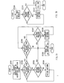
- Next, the automatic antenna control operation of the portable terminal apparatus with the above configuration will be explained in detail below. First, operations when a call request is issued or when the reception condition changes will be explained with reference to FIG.2A.
- When the portable terminal apparatus receives a call start request from a radio base station or when the portable terminal apparatus issues a call start request to the radio base station, transmission/
reception apparatus 102 outputs a signal indicating "call request generation" to antenna extension/contraction control apparatus 103. At this time, transmission/reception apparatus 102 outputs the reception level information of the reception signal currently received byantenna 101 to antenna extension/contraction control apparatus 103 successively. Then, antenna extension/contraction control apparatus 103 detects a "call request generation" or "reception condition change" from the signal input from transmission/reception apparatus 102 (ST 201). - Then, reception
level decision apparatus 105 of antenna extension/contraction control apparatus 103 decides whether the current reception level exceeds predetermined threshold A or not (ST 202). In the case where receptionlevel decision apparatus 105 decides that the reception level is not higher than threshold A, receptionlevel decision apparatus 105 further decides whether the length ofantenna 101 is a maximum or not (ST 203). Here, in the case where receptionlevel decision apparatus 105 decides that the length ofantenna 101 is not a maximum, receptionlevel decision apparatus 105 sends a command for extendingantenna 101 toantenna control apparatus 104. Then,antenna control apparatus 104 performs processing of extending antenna 101 (ST 204). - As described above, when it is predicted that the reception level is low because the antenna length is short, this portable terminal apparatus performs control in such a way that
antenna 101 is extended. Thus, this portable terminal apparatus automatically raises the reception level. As a result, this portable terminal apparatus can improve the communication condition without the need for intervention by the user. - On the other hand, in the case where reception
level decision apparatus 105 decides thatantenna 101 reaches a maximum length in ST 203, the portable terminal apparatus starts a call or continues a call that has already been started (ST 205). - Thus, this portable terminal apparatus does not perform any antenna extending processing if the antenna length is a maximum even if the reception level is low. This makes it possible to avoid an unnecessary process of further extending the antenna, which can no longer be extended. Moreover, not executing such antenna extending processing prevents
antenna 101 from receiving an excessive force. This also has an effect of preventing malfunctions of the antenna. - On the other hand, when reception
level decision apparatus 105 decides that the current reception level exceeds threshold A in ST 202, receptionlevel decision apparatus 105 further decides whether the reception level exceeds threshold B (here, suppose threshold B is greater than threshold A) or not (ST 206). In the case where receptionlevel decision apparatus 105 decides that the reception level is not higher than threshold B in ST 206, the portable terminal apparatus starts a call, or continues a call that has already been started (ST 205). - On the other hand, in the case where reception
level decision apparatus 105 decides that the reception level is higher than threshold B in ST 206, receptionlevel decision apparatus 105 decides whether the length ofantenna 101 is a minimum or not (ST 207). - In the case where reception
level decision apparatus 105 decides that the length ofantenna 101 is not a minimum in ST 207,antenna control apparatus 104 performs processing ofcontracting antenna 101 by a predetermined length (ST 208) and the process goes back to ST 206. Then, receptionlevel decision apparatus 105 again decides whether the reception level with the contracted antenna length exceeds predetermined threshold B or not. Here, in the case where the reception level does not exceed threshold B, the portable terminal apparatus starts a call or continues a call that has already been started (ST 205). On the other hand, in the case wherelevel decision apparatus 105 decides again that the reception level exceeds predetermined threshold B, the processes in ST 207 and ST 208 are repeated until the predetermined reception level is reached. - Thus, when the reception level is too high beyond threshold B, this portable terminal apparatus controls so that
antenna 101 is contracted until the reception level falls below threshold B or the antenna length reaches a minimum. This prevents the reception level from becoming too high, allowing the reception level to be maintained in an optimal condition. - In addition, in the case where the length of
antenna 101 is a minimum in ST 207, the process returns to ST 205 and the portable terminal apparatus starts a call or continues a call that has already been started. - In this way, in the case where the antenna length is a minimum, the processing of
contracting antenna 101 is not executed. This makes it possible to avoid any useless process and prevent extra load onantenna 101. - Next, the operation when a call end request is issued will be explained in detail using the flow chart in FIG.2B.
- In the case where this portable terminal apparatus receives a call end request from the radio base station or when this portable terminal apparatus issues a call end request to the radio base station, transmission/
reception apparatus 102 outputs a signal indicating a "call end request" to antenna extension/contraction control apparatus 103. - Antenna extension/
contraction control apparatus 103 detects the "call end request" signal from the signal input from transmission/reception apparatus 102 (ST 209). Then, receptionlevel decision apparatus 105 decides whether the length ofantenna 101 is a minimum or not (ST 210). In the case where receptionlevel decision apparatus 105 decides that the length ofantenna 101 is a minimum in ST 210, the portable terminal apparatus ends the call (ST 211). Moreover, in the case where receptionlevel decision apparatus 105 decides that the length ofantenna 101 is not a minimum in ST 210,antenna control apparatus 104 performs processing of contracting the length of antenna 101 (ST 212). Then, it is possible to ensure that the length ofantenna 101 is contracted to a minimum by repeating the processing in and after ST 210. - In this way, this portable terminal apparatus automatically contracts the antenna length to a minimum when a call ends, and therefore while the user is not using this portable terminal apparatus, the antenna is always kept to a minimum length. This allows the portable terminal apparatus to prevent the antenna from being damaged without any intervention by the user.
- As described above, this
Embodiment 1 allowsantenna 101 to be automatically adjusted to an appropriate length without the need for the user to pick up the end ofantenna 101 by hand or operate an input apparatus such as a switch. This allows this portable terminal apparatus to always receive signals in optimal conditions without any intervention by the user. It is also possible to avoid such a case where sudden deterioration of the reception condition of the portable terminal apparatus during a call prevents the user from using the portable terminal apparatus. - Furthermore, the portable terminal apparatus of the embodiment above can automatically adjust
antenna 101 to an appropriate length. This eliminates the need for the user to check the reception level shown on the display and adjust the length ofantenna 101 according to the reception level as in the case of the conventional portable terminal apparatus. - Furthermore, the portable terminal apparatus of the embodiment above can also prevent
antenna 101 from being damaged due to an erroneous operation while the user is manually picking upantenna 101. - The portable terminal apparatus of the embodiment above also has two reception level thresholds, which prevent the length of
antenna 101 from becoming longer than necessary. This prevents the user from, for example, touching other people withantenna 101 in the crowd, causing damage toantenna 101. -
Embodiment 1 describes the portable terminal apparatus as an example, but the present invention is also applicable to a stationary terminal apparatus equipped with an extendable antenna. Moreover,Embodiment 1 describes the portable terminal apparatus that communicates voice as an example, but the present invention is also applicable to a portable terminal apparatus that communicates images or other data. - FIG.3 is a front view and side view of a portable phone apparatus according to
Embodiment 2 of the present invention. -
Portable phone apparatus 301 according to this embodiment is a portable phone apparatus provided with a capability of switching between an auto extension/contraction mode similar to that in the portable terminal apparatus ofEmbodiment 1 above and a manual mode that allows the user to adjust the antenna length through button operations. - The portable phone apparatus is configured by a
case 307 in a size that allows the user to carry it by one hand and speak while holding it by one hand. Various operation sections, which will be described later, are provided on the surface ofcase 307. Moreover, various operation sections, which will be described later, are provided insidecase 307. -
Input buttons 305 to enter various kinds of information are provided in the lower part of the top face ofportable phone apparatus 301. A contact sensor is provided beneathinput button 305, which sends input information to a control apparatus, which will be described later.Display apparatus 304 that displays various kinds of input information of the reception level, etc. of the signal received byantenna 300 and processing content is provided in the upper part of the top face ofportable phone apparatus 301. Moreover,speaker 306 that outputs a voice signal sent from another portable phone apparatus is provided in the upper part of the top face ofportable phone apparatus 301. On the other hand,microphone 308 that inputs a voice signal to be sent to the other portable phone apparatus is provided in the lower part of the top face ofportable phone apparatus 301. - Furthermore, antenna extension/
contraction buttons contract antenna 300 are provided close to one another in the upper part of the external side ofportable phone apparatus 301. Antenna extension/contraction button 302 is the button to extendantenna 300. Antenna extension/contraction button 303 is the button to contractantenna 300. Providing antenna extension/contraction buttons contraction buttons input section 305 by one hand. Furthermore, the user can also operate antenna extension/contraction buttons - Next, the configuration of various processing sections provided inside
portable phone apparatus 301 will be explained using FIG.4. -
Portable phone apparatus 301 is provided with transmission/reception apparatus 401 that modulates/demodulates a radio signal sent from another portable phone apparatus and received byantenna 300. The modulated/demodulated signal is sent to coding/decoding apparatus 402. Coding/decoding apparatus 402 performs coding/decoding processing and error correction processing on the input signal and outputs. The signal output from coding/decoding apparatus 402 is sent to controlapparatus 403 that carries out control over various processing apparatuses.Control apparatus 403 performs predetermined processing on this input signal and outputs it to voiceprocessing apparatus 404.Voice processing apparatus 404 performs predetermined processing such as D/A conversion on the input signal and outputs it tospeaker 306.Speaker 306 outputs the input signal as voice. - On the other hand, a voice signal input by
microphone 308 is sent to voiceprocessing apparatus 404.Voice processing apparatus 404 performs predetermined processing such as A/D conversion on the input signal and sends it to controlapparatus 403.Control apparatus 403 performs predetermined processing on the input signal and sends it to coding/decoding apparatus 402. Coding/decoding apparatus 402 performs coding/decoding processing and error correction processing on the input signal and sends it to transmission/reception apparatus 401. Transmission/reception apparatus 401 performs modulation/demodulation processing on the input signal and transmits it to the other portable phone apparatus viaantenna 300. - Furthermore, transmission/
reception apparatus 401 sends the signal received byantenna 300 to callrequest detection apparatus 409 provided incontrol apparatus 403. Callrequest detection apparatus 409 detects a call start requesting signal and a call end requesting signal from the input signal. Then,control section 403 starts or ends a call according to this detection signal. Moreover, callrequest detection apparatus 409 also detects a call start request signal and a call end request signal from an input signal frominput buttons 305. - Furthermore, transmission/
reception apparatus 401 detects the reception level information of the signal received byantenna 300 and outputs it to receptionlevel decision apparatus 408. The "reception condition" referred to here is the reception level of the signal received byantenna 300. Furthermore, the "reception level" referred to here is SIR. Receptionlevel decision apparatus 408 detects the reception level of the signal received byantenna 300 and outputs it to antenna extension/contraction control apparatus 405 provided incontrol apparatus 403. Antenna extension/contraction control apparatus 405 outputs a control signal according to the reception level toantenna drive apparatus 406.Antenna drive apparatus 406 extends/contracts antenna 300 driven by an electric driving means such as an electric motor, etc. according to this control signal. - Moreover,
control apparatus 403 receives various input signals frominput buttons 305 and performs processing according to these input signals.Control apparatus 403 sends this processing content and input information from the input buttons to displayapparatus 304.Display apparatus 304 displays the input information in a visible form. - Furthermore,
control apparatus 403 is also provided withbutton decision apparatus 407 that decides the conditions of antenna extension/contraction buttons Button decision apparatus 407 detects the conditions of antenna extension/contraction buttons contraction control apparatus 405. Antenna extension/contraction control apparatus 405 outputs a control signal according to the reception level toantenna drive apparatus 406.Antenna drive apparatus 406 extends/contracts antenna 300 according to this control signal. - Furthermore, antenna extension/
contraction control apparatus 405 also switches antenna extension/contraction modes from the signal sent frombutton decision apparatus 407. The antenna extension/contraction modes include an auto extension/contraction mode in which the length ofantenna 300 is automatically extended/contracted to a desired length usingantenna drive apparatus 406 under the control of antenna extension/contraction control apparatus 405 and a manual extension/contraction mode in which the length ofantenna 300 is manually extended/contracted by antenna extension/contraction buttons - Next, operations of switching between the auto extension/contraction mode and manual extension/contraction mode by operating antenna extension/
contraction buttons portable phone apparatus 301 will be explained in detail using FIG.5A to FIG.5D. FIG.5A to FIG.5D illustrate button setting patterns of the portable phone apparatus according toEmbodiment 2. - In the case where antenna extension/
contraction button 302 is ON and antenna extension/contraction button 303 is OFF, that is, the status shown in FIG.5A, antenna extension/contraction control apparatus 405 switches the antenna extension/contraction mode to the manual extension/contraction mode. In this case, since only antenna extension/contraction button 302 is ON, antenna extension/contraction control apparatus 405 sends a signal commandingantenna drive apparatus 406 to extendantenna 300.Antenna drive apparatus 406 performs processing of extending the antenna. - Moreover, in the case where antenna extension/
contraction button 302 is OFF and antenna extension/contraction button 303 is ON, that is the status shown in FIG.5B, antenna extension/contraction control apparatus 405 switches the antenna extension/contraction mode to the manual extension/contraction mode. In this case, since only antenna extension/contraction button 303 is ON, antenna extension/contraction control apparatus 405 sends a signal commandingantenna drive apparatus 406 to contractantenna 300. - Furthermore, in the case where both antenna extension/
contraction buttons contraction control apparatus 405 sends a signal commandingantenna drive apparatus 406 to stop extending/contracting antenna 300. Then,antenna drive apparatus 406 stops extending/contracting antenna 300. In this case, it is also possible to adopt a mode in which the length ofantenna 300 is contracted to a minimum and then extension/contraction ofantenna 300 is stopped. - Furthermore, in the case where both antenna extension/
contraction buttons contraction control apparatus 405 switches the antenna extension/contraction mode to the auto extension/contraction mode. Then, antenna extension/contraction control apparatus 405 detects a signal from receptionlevel decision apparatus 408. Then, antenna extension/contraction control apparatus 405 performs control in ST 201 to ST 208 shown in FIG.2A. - As shown above, operating antenna extension/
contraction buttons contract antenna 300, can easily change the extension/contraction mode ofantenna 300. Moreover, it is not necessary to provide an extra button to change the extension/contraction mode ofantenna 300, making it possible to simplify the configuration of the apparatus. - Next, the antenna extension/contraction operation of
portable phone apparatus 301 with the configuration above will be explained in detail using the flow chart in FIG.6. - Antenna extension/
contraction control apparatus 405 decides whether both antenna extension/contraction buttons contraction control apparatus 405 decides that both antenna extension/contraction buttons contraction control apparatus 405 switches the extension/contraction mode to the auto extension/contraction mode. Then, antenna extension/contraction control apparatus 405 executes ST 201 to ST 208 in FIG.2A based on the signal from reception level decision apparatus 408 (ST 502) and the process goes back to the state in ST 501. - In ST 501, in the case where antenna extension/
contraction control apparatus 405 decides that either one of antenna extension/contraction buttons contraction control apparatus 405 further decides the statuses of antenna extension/contraction buttons - In ST 503, in the case where antenna extension/
contraction control apparatus 405 decides that antenna extension/contraction buttons contraction control apparatus 405 sends a signal commandingantenna drive apparatus 406 to stop extension/contraction ofantenna 300. Thus,antenna drive apparatus 406 does not perform any processing. Then, antenna extension/contraction control apparatus 405 returns to the processing in ST 503. - On the other hand, in the case where antenna extension/
contraction control apparatus 405 decides that antenna extension/contraction buttons contraction control apparatus 405 sends a signal commandingantenna drive apparatus 406 to extendantenna 300. Thenantenna drive apparatus 406 performs processing of extending antenna 300 (ST 504). - In the case where antenna extension/
contraction control apparatus 405 decides that antenna extension/contraction buttons contraction control apparatus 405 sends a signal commandingantenna drive apparatus 406 to contractantenna 300. Thenantenna drive apparatus 406 performs processing of contracting antenna 300 (ST 505). - Then, call
request detection apparatus 409 decides whether the call has ended or not (ST 506). - In the case where call
request detection apparatus 409 decides that the call has ended in ST 506, antenna extension/contraction control apparatus 405 performs processing ofcontracting antenna 300 to a minimum length (ST 507). Then,portable phone apparatus 301 ends processing. On the other hand, in the case where callrequest detection apparatus 409 decides that the call has not ended in ST 506, the process returns to ST 503 andportable phone apparatus 301 repeats the same processing as the above. - Then, the extension/contraction operation of
antenna 300 will be explained using FIG.7. -
Antenna 300 is normally housed insideportable phone apparatus 301.Antenna 300 is designed to be exposed fromcase 307 ofportable phone apparatus 301 depending on the reception condition. Moreover, the extension/contraction operation ofantenna 300 can be performed in a stage-less form or in stages like 600, 601, 602 and 603 shown in FIG.6. Among the different states shown in the figure, the state shown in 600 denotes the minimum length ofantenna 300. - As shown above, this
portable phone apparatus 301 allows the user to leaveantenna 300 auto-controlled during normal operation, automatically adjustable to an optimal length. On the other hand, in the case whereextended antenna 300 can cause inconvenience to the user, becauseextended antenna 300 is too long, the user can control the antenna length according to the surrounding situation by manually controllingantenna 300. Here, the case where "extended antenna 300 can cause inconvenience to the user, becauseextended antenna 300 is too long," refers to a case whereextended antenna 300 can annoy other people , becauseextended antenna 300 is too long, orantenna 300 may touch other people and be damaged, etc. - Moreover, this embodiment uses a button-type input apparatus, but any other type, for example, a lever-type or roller-type can also be used.
- This embodiment describes
portable phone apparatus 301 as an example, but the present invention can also be applied to any portable terminal apparatus other thanportable phone apparatus 301. Furthermore, this embodiment is also applicable to a stationary type terminal apparatus other than a portable terminal apparatus with an extendable antenna. - FIG.8 is a block diagram of a communication system according to Embodiment 3 of the present invention.
- This communication system is designed to send antenna extension/contraction information from
radio base station 710 to mobile apparatus 711. Mobile apparatus 711 is a portable terminal apparatus as described inEmbodiment 1. It can also be a portable phone apparatus as described inEmbodiment 2. The parts of mobile apparatus 711 having the same functions as those in FIG.1 are assigned the same reference numerals and their explanations will be omitted. -
Radio base station 710 is provided withcontrol apparatus 701 that processes transmitted/received signals. A signal processed bycontrol apparatus 701 is sent to coding/decoding apparatus 702. Coding/decoding apparatus 702 performs coding/decoding processing and error correction processing on the signal input fromcontrol apparatus 701. Coding/decoding apparatus 702 sends the signal subjected to coding/decoding processing and error correction processing totransmission section 703.Transmission section 703 performs modulation processing on the signal input from the coding/decoding apparatus to send the signal to mobile apparatus 711. - Furthermore,
radio base station 710 is provided withsynchronization section 704 that demodulates the signal received from mobile apparatus 711 viaantenna 705.Synchronization section 704 sends the demodulated signal to the coding/decoding apparatus andantenna control apparatus 706.Antenna control apparatus 706 performs the processing in ST 201 to ST 211 shown in FIG.2 or the processing in ST 501 to ST 507 shown in FIG.4 on the signal input fromsynchronization section 704. Then,antenna control apparatus 706 sends antenna length information to mobile apparatus 711. - Furthermore,
antenna control apparatus 706 is provided inside with receptionlevel sensing apparatus 707 that senses the reception level sent fromsynchronization section 704. The "reception condition" referred to here is a reception level of a signal received fromantenna 101. Moreover, the "reception level" referred to here is SIR. Receptionlevel sensing apparatus 707 sends the sensed reception level to antenna extension/contractioninformation control section 708 provided insideantenna control apparatus 706. Antenna extension/contractioninformation control section 708 controls extension/contraction information ofantenna 101 according to the reception level. Then, antenna extension/contractioninformation control section 708 sends antenna extension/contraction information totransmission section 703. - On the other hand, mobile apparatus 711 is provided with antenna extension/
contraction apparatus 709 that controls the length ofantenna 101 according to the antenna extension/contraction information control signal sent fromradio base station 710. Antenna extension/contraction apparatus 709 adjusts the length ofantenna 101 driven by an electric driving means such as an electric motor, etc. The parts already explained are assigned the same reference numerals and their explanations are omitted. - In the communication system configured as shown above, a signal sent from mobile apparatus 711 is received by
radio base station 710.Antenna control apparatus 706 ofradio base station 710 receives the transmit power control information extracted from the reception signal bysynchronization section 704. In the case of open-loop control, the transmit power control information sent by mobile apparatus 711 is a parameter indicating the reception level in mobile apparatus 711. In radiobase station apparatus 710, receptionlevel sensing apparatus 707 ofantenna control apparatus 706 can predict the reception level at mobile apparatus 711 from the transmit power control information. Antenna extension/contractioninformation control section 708 receives the reception level information of mobile apparatus 711 from receptionlevel sensing apparatus 707 and creates antenna length control information that controls the antenna length of mobile apparatus 711 in the same way as forEmbodiment 1 above. Supposeantenna control apparatus 706 ofradio base station 710 controls the antenna length information of mobile apparatus 711. The antenna length control information is sent fromtransmission section 703 to mobile apparatus 711. - Mobile apparatus 711 receives the antenna length control information sent from
radio base station 710. The antenna length control information received by mobile apparatus 711 is input from transmission/reception apparatus 102 to antenna extension/contraction apparatus 709. Antenna extension/contraction apparatus 709 controls extension/contraction of the length ofantenna 101 according to the antenna length control information. - Thus, this communication system is designed to reduce the size of mobile apparatus 711 by incorporating
antenna control apparatus 706 not in mobile apparatus 711 but inradio base station 710. Using this communication system can provide the user with comfort and convenience of a portable terminal apparatus. - In Embodiment 3,
radio base station 710 predicts the reception level of mobile apparatus 711 and creates antenna length control information according to the flow chart shown in FIG.2, but it is also possible to create antenna length control information such as "extend the antenna" or "contract the antenna" according to two information pieces "increase powers or "decrease powers" indicated by the transmit power control information. That is,synchronization section 704 ofradio base station 710 extracts and receives the transmit power control information received from mobile apparatus 711 and inputs the information to receptionlevel sensing apparatus 707. Receptionlevel sensing apparatus 707 extracts information "increase power" or "decrease power" from the transmit power control information and sends it to antenna extension/contractioninformation control section 708. Antenna extension/contractioninformation control section 708 sends a signal "extend the antenna" in the case of "increase power" or "contract the antenna" in the case of "decrease power" fromtransmission section 703 to mobile apparatus 711. - In this embodiment,
antenna control apparatus 706 is provided inradio base station 710, but it is also possible to implement a system withantenna control apparatus 706 provided in mobile apparatus 711 as shown in FIG.9. The same processing sections as those already explained are assigned the same reference numerals and their explanations are omitted. - Throughout the explanations of the present invention, the mode in which SIR is used as the reception level has been explained, but it is also possible to use Ec/I0, RSCP or RSSI instead of SIR.
- This application is based on the Japanese Patent Application No.HEI 11-9109 filed on January 18, 1999, entire content of which is expressly incorporated by reference herein.
- As described above, the present invention can provide a portable terminal apparatus and control method for the portable terminal apparatus that automatically control the reception apparatus to an optimal length according to the reception condition of the reception apparatus.
Claims (18)
- An antenna control apparatus comprising:a driving section that extends/contracts an antenna by electromotive force;a reception level detection section that detects the reception level of the signal received by said antenna; anda control section that controls said driving section so that an optimal antenna length is obtained according to said reception level.
- The antenna control apparatus according to claim 1, wherein said control section controls the antenna length in such a way that said reception level falls between a predetermined upper limit and lower limit.
- The antenna control apparatus according to claim 1, wherein said control section controls so that the antenna is not further extended when the antenna reaches a maximum length and the antenna is not further contracted when the antenna reaches a minimum length.
- The antenna control apparatus according to claim 2, wherein said control section controls so that the antenna is not further extended when the antenna reaches a maximum length and the antenna is not further contracted when the antenna reaches a minimum length.
- The antenna control apparatus according to claim 1, wherein said driving section further comprising:extension/contraction buttons to manually input an extension/contraction signal to extend/contract the antenna; andan extension/contraction mode switching section that switches between a manual extension/contraction mode that controls the antenna length through this extension/contraction button and an auto extension/contraction mode that controls the antenna length through said control section.
- The antenna control apparatus according to claim 1, further comprising a call request detection section that detects a signal requesting to start a call or end a call, wherein said control section controls, when said call request detection section detects a call end request signal, said driving section so that said antenna is contracted to a minimum length.
- A portable terminal apparatus comprising:a transmission/reception section that transmits/receives information with another portable terminal apparatus;a driving section that extends/contracts an antenna by electromotive force;a reception level detection section that detects the reception level of the signal received by said antenna; anda control section that controls said driving section so that an optimal antenna length is obtained according to said reception level.
- The portable terminal apparatus according to claim 7, wherein said control section controls the antenna length in such a way that said reception level falls between a predetermined upper limit and lower limit.
- The portable terminal apparatus according to claim 7, wherein said control section controls so that the antenna is not further extended when the antenna reaches a maximum length and the antenna is not further contracted when the antenna reaches a minimum length.
- The portable terminal apparatus according to claim 8, wherein said control section controls so that the antenna is not further extended when the antenna reaches a maximum length and the antenna is not further contracted when the antenna reaches a minimum length.
- A portable phone apparatus comprising:buttons for inputting various kinds of information;a display to display various kinds of information;a transmission/reception section to transmit/receive information with another portable phone apparatus;a speaker that outputs a voice signal sent from the other portable phone apparatus;a microphone that captures a voice signal to be sent to the other portable phone apparatus;a driving section that extends/contracts an antenna by electromotive force;a reception level detection section that detects the reception level of the signal received by said antenna; anda control section that controls said driving section so that an optimal antenna length is obtained according to said reception level.
- A radio base station apparatus comprising:a reception level detection section that detects the reception level of a signal received by an antenna of a mobile apparatus based on transmit power control information sent from said mobile apparatus;an antenna extension/contraction information control section that generates antenna length control information that controls the antenna length according to said reception level; anda transmission section that transmits by radio said antenna length control information to said mobile apparatus.
- A radio base station apparatus comprising:a transmit power control information detection section that detects transmit power control information sent from a mobile apparatus;an antenna extension/contraction information control section that generates antenna length control information that controls the antenna length according to the detected transmit power control information; anda transmission section that transmits by radio said antenna length control information to said mobile apparatus.
- A mobile apparatus comprising:a driving section that extends/contracts an antenna by electromotive force; anda control section that controls said driving section so that the antenna length according to the antenna length control information sent from the radio base station apparatus according to claim 12 is obtained.
- An antenna control method that obtains an optimal antenna length by detecting the reception condition of an antenna and controlling a driving section that extends/contracts said antenna by electromotive force according to the detected reception condition.
- A portable terminal apparatus control method that obtains an optimal antenna length by detecting the reception condition of an antenna and controlling a driving section that extends/contracts said antenna by electromotive force according to the detected reception condition.
- A portable phone apparatus control method that obtains an optimal antenna length by detecting the reception condition of an antenna and controlling a driving section that extends/contracts said antenna by electromotive force according to the detected reception condition.
- An antenna control method that controls the antenna length by deciding transmit power control information by a mobile apparatus according to the reception level, receiving said transmit power control information by a radio base station, creating antenna length control information to control the antenna length of said mobile apparatus based on the received transmit power control information, transmitting by radio the created antenna length control information and receiving said antenna length control information by said mobile apparatus.
Applications Claiming Priority (3)
| Application Number | Priority Date | Filing Date | Title |
|---|---|---|---|
| JP910999 | 1999-01-18 | ||
| JP00910999A JP3431526B2 (en) | 1999-01-18 | 1999-01-18 | Radio base station apparatus, mobile station, and antenna control method |
| PCT/JP2000/000101 WO2000042675A1 (en) | 1999-01-18 | 2000-01-12 | Antenna control device and antenna control method |
Publications (1)
| Publication Number | Publication Date |
|---|---|
| EP1067624A1 true EP1067624A1 (en) | 2001-01-10 |
Family
ID=11711472
Family Applications (1)
| Application Number | Title | Priority Date | Filing Date |
|---|---|---|---|
| EP00900342A Withdrawn EP1067624A1 (en) | 1999-01-18 | 2000-01-12 | Antenna control device and antenna control method |
Country Status (4)
| Country | Link |
|---|---|
| EP (1) | EP1067624A1 (en) |
| JP (1) | JP3431526B2 (en) |
| AU (1) | AU2002200A (en) |
| WO (1) | WO2000042675A1 (en) |
Cited By (1)
| Publication number | Priority date | Publication date | Assignee | Title |
|---|---|---|---|---|
| EP1860726A1 (en) * | 2006-05-24 | 2007-11-28 | Samsung Electronics Co., Ltd. | Broadcast receiving antenna system mounted in a wireless terminal |
Family Cites Families (6)
| Publication number | Priority date | Publication date | Assignee | Title |
|---|---|---|---|---|
| JPS57171336U (en) * | 1981-04-20 | 1982-10-28 | ||
| JP2580687Y2 (en) * | 1991-01-30 | 1998-09-10 | アラコ株式会社 | In-vehicle antenna drive |
| JPH08279708A (en) * | 1995-04-05 | 1996-10-22 | Mitsubishi Electric Corp | Antenna device |
| JPH09162620A (en) * | 1995-12-01 | 1997-06-20 | Matsushita Electric Ind Co Ltd | Antenna-controlled receiver |
| EP0800227A3 (en) * | 1996-04-02 | 1998-07-08 | Nec Corporation | Device for controlling expansion/contraction of an antenna in a radio unit and method therefor |
| JPH1117419A (en) * | 1997-06-24 | 1999-01-22 | Nippon Denki Ido Tsushin Kk | Automatic extending/contracting antenna-type portable telephone |
-
1999
- 1999-01-18 JP JP00910999A patent/JP3431526B2/en not_active Expired - Fee Related
-
2000
- 2000-01-12 EP EP00900342A patent/EP1067624A1/en not_active Withdrawn
- 2000-01-12 AU AU20022/00A patent/AU2002200A/en not_active Abandoned
- 2000-01-12 WO PCT/JP2000/000101 patent/WO2000042675A1/en not_active Ceased
Non-Patent Citations (1)
| Title |
|---|
| See references of WO0042675A1 * |
Cited By (2)
| Publication number | Priority date | Publication date | Assignee | Title |
|---|---|---|---|---|
| EP1860726A1 (en) * | 2006-05-24 | 2007-11-28 | Samsung Electronics Co., Ltd. | Broadcast receiving antenna system mounted in a wireless terminal |
| US7450075B2 (en) | 2006-05-24 | 2008-11-11 | Samsung Electronics Co., Ltd. | Broadcasting receiving antenna system mounted in a wireless terminal |
Also Published As
| Publication number | Publication date |
|---|---|
| WO2000042675A1 (en) | 2000-07-20 |
| AU2002200A (en) | 2000-08-01 |
| JP2000209010A (en) | 2000-07-28 |
| JP3431526B2 (en) | 2003-07-28 |
Similar Documents
| Publication | Publication Date | Title |
|---|---|---|
| CN101690350B (en) | Mobile communication terminal and transmission power control method employed in mobile communication terminal | |
| JP2994274B2 (en) | Portable mobile radio terminal | |
| EP2134130A3 (en) | Transmission power control device and method, mobile station, and communication device in mobile communication system | |
| JPH0818500A (en) | Portable radio | |
| CN1229328A (en) | Method for switching between radiotelephone unit and radiotelephone base station | |
| EP1761019B1 (en) | Mobile robot system and method of remote-controlling the same | |
| EP1067624A1 (en) | Antenna control device and antenna control method | |
| US5148470A (en) | Radio telephone apparatus having an instantaneous conversation function | |
| JP2001103565A (en) | Mobile wireless terminal | |
| US20070191069A1 (en) | Radio communication terminal device and radio communication function control method | |
| CN1691524B (en) | Radio frequency output power control method of wireless communication device | |
| JP2005260434A (en) | Mobile communication terminal | |
| EP1646260A3 (en) | Control method, control program and mobile communication terminal device for soft handoff in a mobile communications system | |
| WO2007148391A1 (en) | Multi-system radio communication device | |
| JPH06311067A (en) | Wireless telephone | |
| KR100370969B1 (en) | Calling connection circuit of mobile phone | |
| JP3607631B2 (en) | Mobile communication terminal | |
| US6941155B1 (en) | Portable telephone apparatus and changing method of answering method of the same | |
| JPH07273719A (en) | Power supply control circuit for mobile phones | |
| KR100464495B1 (en) | A cordless telephone and a operating method preparation for interruption of electric power | |
| KR20000025233A (en) | Apparatus for driving antenna automatically in mobile communication terminal and method for controlling automatic driving of antenna | |
| JPH06225351A (en) | Wireless telephone | |
| KR19980083395A (en) | Method of controlling antenna of telephone and telephone having automatic control antenna for performing the same | |
| JPH0613955A (en) | Wireless communication device | |
| JPH1084308A (en) | Wireless telephone and wireless telephone system |
Legal Events
| Date | Code | Title | Description |
|---|---|---|---|
| PUAI | Public reference made under article 153(3) epc to a published international application that has entered the european phase |
Free format text: ORIGINAL CODE: 0009012 |
|
| AK | Designated contracting states |
Kind code of ref document: A1 Designated state(s): AT BE CH CY DE DK ES FI FR GB GR IE IT LI LU MC NL PT SE |
|
| 17P | Request for examination filed |
Effective date: 20001222 |
|
| STAA | Information on the status of an ep patent application or granted ep patent |
Free format text: STATUS: THE APPLICATION HAS BEEN WITHDRAWN |
|
| 18W | Application withdrawn |
Effective date: 20030128 |