EP1067623A2 - Deployment of dual reflector systems - Google Patents
Deployment of dual reflector systems Download PDFInfo
- Publication number
- EP1067623A2 EP1067623A2 EP00113920A EP00113920A EP1067623A2 EP 1067623 A2 EP1067623 A2 EP 1067623A2 EP 00113920 A EP00113920 A EP 00113920A EP 00113920 A EP00113920 A EP 00113920A EP 1067623 A2 EP1067623 A2 EP 1067623A2
- Authority
- EP
- European Patent Office
- Prior art keywords
- arm
- reflector
- antenna
- arm assembly
- support structure
- Prior art date
- Legal status (The legal status is an assumption and is not a legal conclusion. Google has not performed a legal analysis and makes no representation as to the accuracy of the status listed.)
- Granted
Links
Images
Classifications
-
- H—ELECTRICITY
- H01—ELECTRIC ELEMENTS
- H01Q—ANTENNAS, i.e. RADIO AERIALS
- H01Q1/00—Details of, or arrangements associated with, antennas
- H01Q1/12—Supports; Mounting means
- H01Q1/1235—Collapsible supports; Means for erecting a rigid antenna
-
- H—ELECTRICITY
- H01—ELECTRIC ELEMENTS
- H01Q—ANTENNAS, i.e. RADIO AERIALS
- H01Q1/00—Details of, or arrangements associated with, antennas
- H01Q1/08—Means for collapsing antennas or parts thereof
-
- H—ELECTRICITY
- H01—ELECTRIC ELEMENTS
- H01Q—ANTENNAS, i.e. RADIO AERIALS
- H01Q1/00—Details of, or arrangements associated with, antennas
- H01Q1/27—Adaptation for use in or on movable bodies
- H01Q1/28—Adaptation for use in or on aircraft, missiles, satellites, or balloons
- H01Q1/288—Satellite antennas
-
- H—ELECTRICITY
- H01—ELECTRIC ELEMENTS
- H01Q—ANTENNAS, i.e. RADIO AERIALS
- H01Q15/00—Devices for reflection, refraction, diffraction or polarisation of waves radiated from an antenna, e.g. quasi-optical devices
- H01Q15/14—Reflecting surfaces; Equivalent structures
- H01Q15/16—Reflecting surfaces; Equivalent structures curved in two dimensions [2D], e.g. paraboloidal
- H01Q15/161—Collapsible reflectors
-
- H—ELECTRICITY
- H01—ELECTRIC ELEMENTS
- H01Q—ANTENNAS, i.e. RADIO AERIALS
- H01Q15/00—Devices for reflection, refraction, diffraction or polarisation of waves radiated from an antenna, e.g. quasi-optical devices
- H01Q15/14—Reflecting surfaces; Equivalent structures
- H01Q15/16—Reflecting surfaces; Equivalent structures curved in two dimensions [2D], e.g. paraboloidal
- H01Q15/161—Collapsible reflectors
- H01Q15/162—Collapsible reflectors composed of a plurality of rigid panels
-
- H—ELECTRICITY
- H01—ELECTRIC ELEMENTS
- H01Q—ANTENNAS, i.e. RADIO AERIALS
- H01Q19/00—Combinations of primary active antenna elements and units with secondary devices, e.g. with quasi-optical devices, for giving the antenna a desired directional characteristic
- H01Q19/10—Combinations of primary active antenna elements and units with secondary devices, e.g. with quasi-optical devices, for giving the antenna a desired directional characteristic using reflecting surfaces
- H01Q19/12—Combinations of primary active antenna elements and units with secondary devices, e.g. with quasi-optical devices, for giving the antenna a desired directional characteristic using reflecting surfaces wherein the surfaces are concave
- H01Q19/17—Combinations of primary active antenna elements and units with secondary devices, e.g. with quasi-optical devices, for giving the antenna a desired directional characteristic using reflecting surfaces wherein the surfaces are concave the primary radiating source comprising two or more radiating elements
-
- Y—GENERAL TAGGING OF NEW TECHNOLOGICAL DEVELOPMENTS; GENERAL TAGGING OF CROSS-SECTIONAL TECHNOLOGIES SPANNING OVER SEVERAL SECTIONS OF THE IPC; TECHNICAL SUBJECTS COVERED BY FORMER USPC CROSS-REFERENCE ART COLLECTIONS [XRACs] AND DIGESTS
- Y10—TECHNICAL SUBJECTS COVERED BY FORMER USPC
- Y10S—TECHNICAL SUBJECTS COVERED BY FORMER USPC CROSS-REFERENCE ART COLLECTIONS [XRACs] AND DIGESTS
- Y10S343/00—Communications: radio wave antennas
- Y10S343/02—Satellite-mounted antenna
Definitions
- This invention relates generally to a system and method for the deployment of dual reflectors and, more particularly, to a system and method for the deployment of a side-fed dual reflector system used in connection with a Ka band satellite.
- Various communication systems make use of satellites orbiting the Earth in a geosynchronous orbit, where the satellites are maintained at the same location relative to the Earth or non-geosynchronous orbit, where the satellites do not maintain the same relative position.
- a satellite uplink communications signal is transmitted to the satellite from one or more ground stations, and then re-transmitted by the satellite to the Earth as a downlink communications signal to cover a desirable reception area depending on the particular use.
- the uplink and downlink signals are transmitted at a particular frequency bandwidth, such as the Ka frequency bandwidth, and are frequently coded.
- the satellite is equipped with antenna system(s) including a plurality of antenna feeds that receive the uplink signals and direct the downlink signals to the Earth.
- the configuration of the antenna feeds and associated antenna optics of the antenna system is designed to provide coverage over a specifically defined area on the Earth, such as the continental United States, although coverage could also be global.
- a downlink antenna feed array including a plurality of antenna feeds may be positioned relative to a sub-reflector and main reflector, where the sub-reflector receives the beams from the feeds and directs the beams towards the main reflector to be directed towards the Earth.
- the orientation of the feed array, sub-reflector and main reflector can take various geometries and configurations depending on a particular design. These designs require that the sub-reflector and main reflector be positioned at select locations and orientations relative to the feed array depending on the focal lengths of the design.
- the feed array and reflectors need to be mounted on a supporting structure in a manner that minimizes use of the available real estate on the satellite.
- the antenna system must be compact and lightweight, but be strong enough to survive the satellite launch and space environment, as well as fit within the launch vehicle fairing.
- these designs require that the reflectors be at least partially stowed in a folded position during launch, and later deployed once the satellite is in orbit.
- a method and system for deploying a multiple reflector antenna system includes an antenna structure mounted to a satellite, where an antenna feed array is mounted to the antenna structure.
- a single articulated antenna arm assembly is mounted to the antenna structure by a first deployment device, such as spring loaded hinge.
- the arm assembly includes a first arm on which is mounted a first reflector, and a second arm on which is mounted a second reflector.
- the first and second arms are connected to each other by a second deployment device, such as a spring loaded hinge, such that the reflectors oppose each other when the arm assembly is in the stowed position.
- a plurality of launch locks hold the arm assembly in the stowed position against the bias of the hinges prior to deployment.
- the launch locks are released in a predetermined sequence such that the arm assembly first moves away from the feed array under the bias of the first hinge, and then the second arm moves away from the first arm under the bias of the second hinge.
- the feed array and the first and second reflectors are oriented relative to each other in a side-fed geometry.
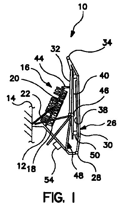
- FIG. 1 shows a side plan view of a multi-reflector antenna system 10 including an integrated antenna mounting structure 12 secured to a satellite platform or bus 14 (partially shown herein) at a strategic location, such as the nadir facing portion of the satellite, depending on the particular design requirements of the antenna and satellite system.
- the antenna system 10 is one of a plurality of similar antenna systems mounted to the bus 14.
- a feed array 16 including a plurality of antenna feed horns 18 is secured to a mounting plate 20 so that the horns 18 are arranged along a predetermined contour consistent with the antenna design.
- the mounting plate 20 is mounted to the antenna structure 12 so that the feed array 16 is positioned at a particular location and orientation that is also consistent with the antenna design.
- a notional supporting bracket 22 is connected to the plate 20 and the structure 12 as shown.
- a single articulated antenna arm assembly 26 is connected to the antenna structure 12 by a first spring-biased deployment hinge 28.
- the deployment hinge 28 is in a spring loaded condition when the assembly 26 is in the stowed position.
- the bias of the deployment hinge 28 provides a force such that when the antenna system 10 is deployed, the arm assembly 26 will move away from the satellite at a predetermined rate and force.
- the antenna arm assembly 26 includes a first antenna arm 30 and a second antenna arm 32 connected together by a second spring-biased deployment hinge 34.
- the deployment hinges 28 and 34 can be any deployment hinge or mechanism available in the art suitable for the purposes of the present invention as described herein.
- the arms 30 and 32 can be made of any suitable material or alloy, such as a graphite composite, that will satisfy the environmental requirements.
- a main reflector 38 is mounted to the arm 30 and a sub-reflector 40 is mounted to the arm 32 so that the reflectors 38 and 40 directly oppose each other and are substantially parallel in the stowed state.
- the reflectors 38 and 40 can be made of any suitable reflector material known in the art, such as a graphite composite, and be mounted to the respective arm 30 or 32 in any suitable manner consistent with the discussion herein, such as by a lightweight mechanical connection.
- the antenna system 10 includes a plurality of launch locks that maintain the antenna arm assembly 26 in the stowed position against the bias of the hinges 28 and 34 prior to being deployed.
- the antenna system 10 incorporates five launch locks for suitable stowage.
- each launch lock includes an electrical device that receives an electrical signal that disengages a mechanical connection, Of course, any launch lock suitable for the purposes described herein can be used.
- a reflector forward launch lock 44 is connected to the antenna feed mounting plate 20 and the arm 32 as shown. Additionally, two aft reflector launch locks 46 (nearside and farside) are mounted to the reflectors (38, 40).
- Launch locks 46 connect the reflectors to launch lock support structure 48, for example, consisting of three support struts that are connected to the antenna structure 12, as shown. Further, a reflector internal launch lock 50 connects the main reflector 38 and subreflector 40. A structure launch lock 54 is provided to connect the antenna structure 12 to the satellite bus 14.
- the launch locks 44, 46, 50, and 54 are restrained (locked), and the hinges 28 and 34 are under spring tension.
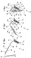
- the launch locks 44 and 46 are first released from the arm 32, and reflectors 38, 40 so that the spring bias of the hinge 28 causes the arm assembly 26 to move away from the feed array 16, as shown in the partially deployed state in Figure 2.
- the launch lock 50 has not yet been released because when the assembly 26 is proximate to the feed array 16 in the stowed position, the arm 32 would contact the feed array 16 if it were released.
- the launch lock 50 is released so that the arm 32 is deployed by the bias of the hinge 34.
- This launch lock (50) function can also be achieved through deployment rate control of the hinges. Additionally, the structure launch lock 54 is also released.
- Figure 3 shows the antenna system 10 when all of the launch locks 44, 46, 50, and 54 have been released and the arm assembly 26 fully deployed.
- the launch locks 44, 46, 50, and 54 and the launch lock support structure 48 are not shown in this figure for clarity purposes.
- the orientation of the feed array 16, the sub-reflector 40, and the main reflector 38 are in a side-fed geometry.
- the sub-reflector 40 receives the beams from the feed horns 18, and directs the beams toward the main reflector 38 in a manner which satisfies the focal length of the reflector 38.
- the main reflector 38 directs the beams towards the Earth over the desired coverage area.
- the sub-reflector 40 has a hyperbolic contour and the main reflector 38 has a parabolic contour.
- a more detailed discussion of a side-fed antenna system can be found in U.S. Patent Application Serial No. 09/232,452, titled Side-Fed Dual Reflector System for Cellular Coverage, filed January 15, 1999.
- other antenna configurations and designs can be provided within the scope of the present invention.
Landscapes
- Physics & Mathematics (AREA)
- Electromagnetism (AREA)
- Engineering & Computer Science (AREA)
- Astronomy & Astrophysics (AREA)
- General Physics & Mathematics (AREA)
- Remote Sensing (AREA)
- Aviation & Aerospace Engineering (AREA)
- Aerials With Secondary Devices (AREA)
- Details Of Aerials (AREA)
- Variable-Direction Aerials And Aerial Arrays (AREA)
Abstract
Description
Claims (8)
- A dual reflector system comprising:a support structure;an articulating arm assembly mounted to the support structure by a first actuating mechanism, said arm assembly including a first arm and a second arm being connected together by a second actuating mechanism; anda first reflector mounted to the first arm and a second reflector mounted to the second arm such that the first and second reflectors directly oppose each other when the arm assembly is in a stowed state, wherein the first arm articulates on the first actuating mechanism and the second arm articulates on the second mechanism to deploy the arm assembly and the reflector system to a deployed state.
- The system according to claim 1 wherein the first and second actuating mechanisms are spring loaded hinges.
- The system according to claim 1 wherein the arm assembly is held in the stowed state by a plurality of locking mechanisms.
- A dual reflector antenna system for use in connection with a communications satellite, said antenna system comprising:a support structure mounted to the satellite;an antenna feed array including a plurality of antenna feeds positioned on a feed mounting plate, said mounting plate being mounted to the support structure;an articulating arm assembly mounted to the support structure by a first actuating mechanism, said arm assembly including a first arm and a second arm being connected together by a second actuating mechanism;a first reflector mounted to the first arm and a second reflector mounted to the second arm such that the first and second reflectors directly oppose each other when the arm assembly is in a stowed state; anda plurality of launch lock mechanisms connected to the arm and reflector assembly, said plurality of lock mechanisms maintaining the arm assembly in the stowed state, said launch lock mechanisms being released to deploy the antenna system, where the first arm articulates on the first actuating mechanism and the second arm articulates on the second actuating mechanism to a deployed state that defines a predetermined antenna position and orientation between the antenna feed array and the first and second reflectors.
- The system according to claim 4, wherein the first and second actuating mechanisms are spring loaded hinges that are held under a spring bias when the arm assembly is in the stowed state, said hinges causing the first and second arms to move when the launch lock mechanisms are released.
- The system according to claim 4 wherein the plurality of launch lock mechanisms includes a first set of launch lock(s) connecting the reflectors and a launch lock support structure, which is in turn connected to the antenna support structure, a second launch lock connecting the second arm and the antenna feed mounting plate, and a third launch lock connecting the first and second reflectors.
- The system according to claim 4 wherein the antenna feed array and the first and second reflectors are positioned in a side-fed orientation when the system is in the deployed state.
- A method of deploying a dual reflector system, comprising:providing a support structure;providing an articulated arm and reflector assembly mounted to the support structure by a first actuating mechanism;connecting a first arm and a second arm of the articulated arm assembly by a second actuating mechanism;positioning the reflector system in a stowed position by actuating the first and second actuating mechanisms so that the first and second reflectors directly oppose each other and the arm assembly is positioned proximate the support structure;providing a plurality of locking mechanisms connected to the arm and reflector assembly to hold the articulated arm assembly in the stowed position; anddeploying the reflector system from the stowed position to a deployed position by releasing the locking mechanisms so that the arm assembly articulates on the first actuating mechanism to move away from the support structure and the second arm articulates on the second actuating mechanism to move away from the first arm.
Applications Claiming Priority (2)
| Application Number | Priority Date | Filing Date | Title |
|---|---|---|---|
| US346193 | 1999-07-01 | ||
| US09/346,193 US6124835A (en) | 1999-07-01 | 1999-07-01 | Deployment of dual reflector systems |
Publications (3)
| Publication Number | Publication Date |
|---|---|
| EP1067623A2 true EP1067623A2 (en) | 2001-01-10 |
| EP1067623A3 EP1067623A3 (en) | 2002-07-31 |
| EP1067623B1 EP1067623B1 (en) | 2004-02-25 |
Family
ID=23358353
Family Applications (1)
| Application Number | Title | Priority Date | Filing Date |
|---|---|---|---|
| EP00113920A Expired - Lifetime EP1067623B1 (en) | 1999-07-01 | 2000-06-30 | Deployment of dual reflector systems |
Country Status (5)
| Country | Link |
|---|---|
| US (1) | US6124835A (en) |
| EP (1) | EP1067623B1 (en) |
| JP (1) | JP2001060812A (en) |
| CA (1) | CA2311013C (en) |
| DE (1) | DE60008458T2 (en) |
Cited By (2)
| Publication number | Priority date | Publication date | Assignee | Title |
|---|---|---|---|---|
| CN108327932A (en) * | 2018-01-31 | 2018-07-27 | 安徽大学 | Human-shaped rod unilateral driving mechanism with radial pretension |
| CN111193095A (en) * | 2020-01-06 | 2020-05-22 | 西南电子技术研究所(中国电子科技集团公司第十研究所) | Spaceborne Antenna Deployable Mechanism |
Families Citing this family (17)
| Publication number | Priority date | Publication date | Assignee | Title |
|---|---|---|---|---|
| US6366255B1 (en) * | 2000-09-15 | 2002-04-02 | Space Systems/Loral, Inc. | Main reflector and subreflector deployment and storage systems |
| US6504514B1 (en) | 2001-08-28 | 2003-01-07 | Trw Inc. | Dual-band equal-beam reflector antenna system |
| US6580399B1 (en) * | 2002-01-11 | 2003-06-17 | Northrop Grumman Corporation | Antenna system having positioning mechanism for reflector |
| US6943745B2 (en) * | 2003-03-31 | 2005-09-13 | The Boeing Company | Beam reconfiguration method and apparatus for satellite antennas |
| EP1735213B1 (en) * | 2004-04-08 | 2015-03-11 | Astrium Limited | Deployable boom |
| US7602349B2 (en) * | 2006-02-24 | 2009-10-13 | Lockheed Martin Corporation | System of stowing and deploying multiple phased arrays or combinations of arrays and reflectors |
| FR2902082B1 (en) * | 2006-06-12 | 2009-10-30 | Alcatel Sa | SPATIAL APPENDICES DEPLOYMENT SYSTEM AND SPATIAL APPENDIX COMPRISING SUCH A SYSTEM |
| KR101299240B1 (en) | 2009-10-28 | 2013-08-27 | 주식회사 팔콘 | Flexible Satellite Antenna Apparatus Which Have Signal Sensing Part And Cable Fixxing Clip |
| DE102009046293B4 (en) * | 2009-11-02 | 2013-03-28 | Repower Systems Ag | Rotor blade with drainage hole |
| RU2414028C1 (en) * | 2010-03-25 | 2011-03-10 | Государственное образовательное учреждение высшего профессионального образования Марийский государственный технический университет | Articulated joint for collapsible reflector of space antenna |
| EP2643882B1 (en) | 2010-12-15 | 2014-04-16 | Skybox Imaging, Inc. | Integrated antenna system for imaging microsatellites |
| CN102923319B (en) * | 2012-11-16 | 2015-11-18 | 上海宇航系统工程研究所 | A kind of aerospacecraft roof type unfolding and locking device |
| US10053240B1 (en) | 2016-05-20 | 2018-08-21 | Space Systems/Loral, Llc | Stowage, deployment and positioning of rigid antenna reflectors on a spacecraft |
| FR3060867B1 (en) * | 2016-12-20 | 2019-05-17 | Thales | DEPLOYABLE SOURCE BLOCK ARCHITECTURE, COMPACT AND SATELLITE ANTENNA COMPRISING SUCH AN ARCHITECTURE |
| US10957986B2 (en) | 2017-08-04 | 2021-03-23 | Space Systems/Loral, Llc | Reconfigurable spacecraft with a hold-down assembly for a rigid reflector |
| US11688932B2 (en) * | 2020-02-07 | 2023-06-27 | Hedron Space Inc. | Satellite antenna |
| US20260074433A1 (en) * | 2024-09-06 | 2026-03-12 | Macdonald, Dettwiler And Associates Corporation | Foldable reflector pallet and method of deploying a foldable reflector pallet |
Family Cites Families (7)
| Publication number | Priority date | Publication date | Assignee | Title |
|---|---|---|---|---|
| FR2517626A1 (en) * | 1981-12-04 | 1983-06-10 | Europ Agence Spatiale | ORBITAL SPACE ENGINE, IN PARTICULAR SATELLITE, WITH MULTIPLE MISSIONS |
| DE3423526A1 (en) * | 1984-06-26 | 1986-01-02 | Messerschmitt-Bölkow-Blohm GmbH, 8012 Ottobrunn | FOLDABLE AND REFOLDABLE ANTENNA REFLECTOR |
| US4771293A (en) * | 1984-11-07 | 1988-09-13 | The General Electric Company P.L.C. | Dual reflector folding antenna |
| US5642122A (en) * | 1991-11-08 | 1997-06-24 | Teledesic Corporation | Spacecraft antennas and beam steering methods for satellite communciation system |
| US5673459A (en) * | 1994-09-28 | 1997-10-07 | Space Systems/Loral, Inc. | Deployment hinge apparatus |
| US5485168A (en) * | 1994-12-21 | 1996-01-16 | Electrospace Systems, Inc. | Multiband satellite communication antenna system with retractable subreflector |
| US5644322A (en) * | 1995-06-16 | 1997-07-01 | Space Systems/Loral, Inc. | Spacecraft antenna reflectors and stowage and restraint system therefor |
-
1999
- 1999-07-01 US US09/346,193 patent/US6124835A/en not_active Expired - Fee Related
-
2000
- 2000-06-08 CA CA002311013A patent/CA2311013C/en not_active Expired - Fee Related
- 2000-06-29 JP JP2000195624A patent/JP2001060812A/en active Pending
- 2000-06-30 EP EP00113920A patent/EP1067623B1/en not_active Expired - Lifetime
- 2000-06-30 DE DE60008458T patent/DE60008458T2/en not_active Expired - Fee Related
Cited By (3)
| Publication number | Priority date | Publication date | Assignee | Title |
|---|---|---|---|---|
| CN108327932A (en) * | 2018-01-31 | 2018-07-27 | 安徽大学 | Human-shaped rod unilateral driving mechanism with radial pretension |
| CN108327932B (en) * | 2018-01-31 | 2019-07-26 | 安徽大学 | Human-shaped rod unilateral driving mechanism with radial pretension |
| CN111193095A (en) * | 2020-01-06 | 2020-05-22 | 西南电子技术研究所(中国电子科技集团公司第十研究所) | Spaceborne Antenna Deployable Mechanism |
Also Published As
| Publication number | Publication date |
|---|---|
| DE60008458D1 (en) | 2004-04-01 |
| EP1067623B1 (en) | 2004-02-25 |
| JP2001060812A (en) | 2001-03-06 |
| CA2311013A1 (en) | 2001-01-01 |
| EP1067623A3 (en) | 2002-07-31 |
| DE60008458T2 (en) | 2004-07-22 |
| CA2311013C (en) | 2002-11-12 |
| US6124835A (en) | 2000-09-26 |
Similar Documents
| Publication | Publication Date | Title |
|---|---|---|
| EP1067623B1 (en) | Deployment of dual reflector systems | |
| US4562441A (en) | Orbital spacecraft having common main reflector and plural frequency selective subreflectors | |
| Rao | Advanced antenna technologies for satellite communications payloads | |
| EP3024732B1 (en) | Side-by-side dual-launch arrangement with improved payload compatibility | |
| US7602349B2 (en) | System of stowing and deploying multiple phased arrays or combinations of arrays and reflectors | |
| US9248922B1 (en) | Reflector deployment techniques for satellites | |
| EP1735213B1 (en) | Deployable boom | |
| US7036772B2 (en) | Spacecraft with extensible radiators | |
| US6366255B1 (en) | Main reflector and subreflector deployment and storage systems | |
| US5966104A (en) | Antenna having movable reflectors | |
| WO2022260741A2 (en) | Adaptable, reconfigurable mobile very small aperture (vsat) satellite communication terminal using an electronically scanned array (esa) | |
| US20180370657A1 (en) | High capacity communication satellite | |
| US6580399B1 (en) | Antenna system having positioning mechanism for reflector | |
| CA2359631A1 (en) | Side-fed offset cassegrain antenna with main reflector gimbal | |
| US7180470B1 (en) | Enhanced antenna stowage and deployment system | |
| Mini et al. | European large deployable antenna: development status and applications | |
| US20260074433A1 (en) | Foldable reflector pallet and method of deploying a foldable reflector pallet | |
| US7548218B2 (en) | Isostatic support structure or fixed or re-orientable large size antenna reflectors | |
| CA3284629A1 (en) | Foldable reflector pallet and method of deploying a foldable reflector pallet | |
| Wong et al. | TDRSS spacecraft antenna farm | |
| You et al. | Design Case of Typical Spacecraft Antenna System | |
| Imbriale et al. | The Orbiters | |
| Yasaka et al. | Multi-band multi-beam antenna complex for orbit experiment | |
| Mini et al. | European large deployable antenna (12 meter): Development status and applications | |
| Taylor et al. | Geostationary small satellite for operationally responsive space (ORS) communications missions |
Legal Events
| Date | Code | Title | Description |
|---|---|---|---|
| PUAI | Public reference made under article 153(3) epc to a published international application that has entered the european phase |
Free format text: ORIGINAL CODE: 0009012 |
|
| AK | Designated contracting states |
Kind code of ref document: A2 Designated state(s): AT BE CH CY DE DK ES FI FR GB GR IE IT LI LU MC NL PT SE |
|
| AX | Request for extension of the european patent |
Free format text: AL;LT;LV;MK;RO;SI |
|
| PUAL | Search report despatched |
Free format text: ORIGINAL CODE: 0009013 |
|
| AK | Designated contracting states |
Kind code of ref document: A3 Designated state(s): AT BE CH CY DE DK ES FI FR GB GR IE IT LI LU MC NL PT SE |
|
| AX | Request for extension of the european patent |
Free format text: AL;LT;LV;MK;RO;SI |
|
| 17P | Request for examination filed |
Effective date: 20030108 |
|
| AKX | Designation fees paid |
Designated state(s): DE FR GB IT |
|
| GRAP | Despatch of communication of intention to grant a patent |
Free format text: ORIGINAL CODE: EPIDOSNIGR1 |
|
| RAP1 | Party data changed (applicant data changed or rights of an application transferred) |
Owner name: NORTHROP GRUMMAN CORPORATION |
|
| RAP1 | Party data changed (applicant data changed or rights of an application transferred) |
Owner name: NORTHROP GRUMMAN CORPORATION |
|
| GRAS | Grant fee paid |
Free format text: ORIGINAL CODE: EPIDOSNIGR3 |
|
| GRAA | (expected) grant |
Free format text: ORIGINAL CODE: 0009210 |
|
| RIN1 | Information on inventor provided before grant (corrected) |
Inventor name: NGUYEN, STEPHEN D. Inventor name: WILKEN, MARK R. Inventor name: SCARANGELLO, JOSEPH G. Inventor name: HOEY, LEONARD A. Inventor name: HUEBERT, DEAN R. |
|
| AK | Designated contracting states |
Kind code of ref document: B1 Designated state(s): DE FR GB IT |
|
| REG | Reference to a national code |
Ref country code: GB Ref legal event code: FG4D |
|
| REG | Reference to a national code |
Ref country code: IE Ref legal event code: FG4D |
|
| REF | Corresponds to: |
Ref document number: 60008458 Country of ref document: DE Date of ref document: 20040401 Kind code of ref document: P |
|
| PG25 | Lapsed in a contracting state [announced via postgrant information from national office to epo] |
Ref country code: GB Free format text: LAPSE BECAUSE OF NON-PAYMENT OF DUE FEES Effective date: 20040630 |
|
| ET | Fr: translation filed | ||
| PLBE | No opposition filed within time limit |
Free format text: ORIGINAL CODE: 0009261 |
|
| STAA | Information on the status of an ep patent application or granted ep patent |
Free format text: STATUS: NO OPPOSITION FILED WITHIN TIME LIMIT |
|
| PG25 | Lapsed in a contracting state [announced via postgrant information from national office to epo] |
Ref country code: DE Free format text: LAPSE BECAUSE OF NON-PAYMENT OF DUE FEES Effective date: 20050101 |
|
| 26N | No opposition filed |
Effective date: 20041126 |
|
| GBPC | Gb: european patent ceased through non-payment of renewal fee |
Effective date: 20040630 |
|
| REG | Reference to a national code |
Ref country code: IE Ref legal event code: MM4A |
|
| PG25 | Lapsed in a contracting state [announced via postgrant information from national office to epo] |
Ref country code: IT Free format text: LAPSE BECAUSE OF NON-PAYMENT OF DUE FEES Effective date: 20050630 |
|
| PG25 | Lapsed in a contracting state [announced via postgrant information from national office to epo] |
Ref country code: FR Free format text: LAPSE BECAUSE OF NON-PAYMENT OF DUE FEES Effective date: 20040630 |
|
| REG | Reference to a national code |
Ref country code: FR Ref legal event code: ST Effective date: 20111007 |