EP1067464A2 - Method and apparatus for fast fourier transform calculation - Google Patents
Method and apparatus for fast fourier transform calculation Download PDFInfo
- Publication number
- EP1067464A2 EP1067464A2 EP00870161A EP00870161A EP1067464A2 EP 1067464 A2 EP1067464 A2 EP 1067464A2 EP 00870161 A EP00870161 A EP 00870161A EP 00870161 A EP00870161 A EP 00870161A EP 1067464 A2 EP1067464 A2 EP 1067464A2
- Authority
- EP
- European Patent Office
- Prior art keywords
- butterfly
- codes
- group
- array
- elements
- Prior art date
- Legal status (The legal status is an assumption and is not a legal conclusion. Google has not performed a legal analysis and makes no representation as to the accuracy of the status listed.)
- Withdrawn
Links
Images




Classifications
-
- G—PHYSICS
- G06—COMPUTING OR CALCULATING; COUNTING
- G06F—ELECTRIC DIGITAL DATA PROCESSING
- G06F17/00—Digital computing or data processing equipment or methods, specially adapted for specific functions
- G06F17/10—Complex mathematical operations
- G06F17/14—Fourier, Walsh or analogous domain transformations, e.g. Laplace, Hilbert, Karhunen-Loeve, transforms
- G06F17/141—Discrete Fourier transforms
- G06F17/142—Fast Fourier transforms, e.g. using a Cooley-Tukey type algorithm
Definitions
- the invention relates to power efficient performing of fast transforms, especially Fast Fourier Transforms (FFT).
- FFT Fast Fourier Transforms
- fast transforms for example, fast Fourier transform, fast cosine transformations
- fast cosine transformations for example, fast Fourier transform, fast cosine transformations
- FFT stages are calculated sequentially on a programmable processor or in a time multiplexed hardware processing engine, usually followed by a sequential iteration over each block and the butterflies involved.
- Three nested loops are considered: stage - block - butterfly.
- the access graph shown in Fig. 8 shows which addresses are used for calculation at each moment. The end points of each line represent which elements are used; the length of a line determines the current stage.
- Fig. 7 is the traditional representation of an FFT.
- Fig. 8 shows the access sequence in time. For example, the content of addresses 0 and 16 are used first, followed by addresses 1 and 17, etc. In the second stage, address 0 and 8 are used, 1 and 9, etc.
- the presented scheduling of the butterflies is not optimal when power consumption of the hardware device on which said transform is executed is important.
- the invention presents a method and an apparatus for transforming a first m-dimensional indexed array with N elements into a second m-dimensional indexed array with M elements.
- the first array may be a representation of a physical signal in a telecommunications network or system and the second array represents the transform of this signal or an intermediate array generated as part of a method to obtain the transform.
- the representation of the first array may be formed by indexing time discrete values of a signal into the first array, for example row-by-row, column-column; e.g. by sampling a physical, analog signal.
- telecommunications system any system capable transmitting and receiving signals, such as, but not limited thereto, a computer, a telephone system, a Local Area Network, a Wide Area Network, the Internet, a mobile telecommunications system, a cellular telephone system, a Metropolitan Access network, a satellite communication system radio or television.
- the transform may be a fast Fourier transform so that the time domain signal represented by the first array is transformed into the frequency domain representation of the same signal.
- the present invention also includes the reverse process, i.e. from the transformed signal back to a representation of the physical signal. In one example, this would be transforming an array being a representation in the frequency domain to a representation of a time domain signal.
- the invention presents a method for transforming a first m-dimensional indexed array with N elements into a second m-dimensional indexed array with M elements, said second array being a transform of said first array, said method comprising the steps of executing a plurality of butterfly codes, also denoted calculation method steps or simply butterflies, each butterfly code being characterized by the elements of the indexed arrays accessed by said butterfly code, said method is characterized in that at least part of said butterfly codes are assigned to at least one group of butterfly codes such that butterfly codes within one group are executed sequentially, meaning substantially close after each other in time, and said grouping of butterfly codes enables the use of storage spaces being substantially smaller than then storage space needed to store an array with N elements.
- the storage spaces used are either registers or a distributed memory configuration or a combination thereof. Note that M is often equal to N.
- data locality improvement schedules are presented.
- a full data locality improvement schedule is disclosed while in a second embodiment a partial data locality improvement schedule is shown.
- the full data locality improvement schedule can be described as a method for transforming a first m-dimensional array into a second m-dimensional array, wherein said second array is a transform of said first array.
- Said transform can be a Fourier transform, a cosine transform, a Karhunen-Loève transform, a Hartly transform but the present invention is not limited thereto.
- Said method comprises the steps of executing a plurality of codes, also denoted butterfly codes, each code being characterized by its array variables or array elements it accesses. One can state that said arrays are indexed, meaning that each element of said arrays can be referred to by an index number. Note that with code or butterfly code is meant a calculation method which reads elements of an array and produces new elements.
- a “butterfly” or “butterfly code” is meant a method reading elements and producing from these read elements further elements via operations such as complex additions, subtractions, multiplications and/or divisions.
- a multiplication factor is a parameter, which can vary from execution to execution of said codes while the operations are the same within said codes.
- Said execution is characterized in that said codes are scheduled by grouping in pairs or sets of codes with a maximal distance in index space between the array variables accessed by said codes. Said pairs of indices are placed in a predetermined ordering. In a particular example said predetermined ordering is address bit-reversed.
- distance is meant the index difference of the elements of the array under consideration.
- Distance can also be denoted as a window.
- maximal is meant those indices having the largest index difference when considering all codes needed to describe the transformation under consideration.
- the selected codes are preferably ordered in a binary tree with, as top node, one of said pair of codes according to their related maximal distance wherein higher distance of such code implies closer placement to the top node of said tree.
- a binary tree can be constructed for each pair of codes.
- the execution order of said ordered codes is determined by traversing said binary tree in a depth-first manner. Note that this is done for each pair.
- the improved data locality obtained by the above described scheduling is exploited because during said execution of said scheduled codes data is shared between at least part of said pairs of codes subsequently scheduled after one another. This data sharing is done via small memories, often denoted registers, register files, being capable of storing a few elements, possible a single element.
- Said small memories are local to the data path of the hardware device executing said application. Note that with “subsequently scheduled” is meant scheduled soon after each other in time. Some intermediate operations are possible depending on the amount of elements that said data sharing memories can store.
- During said execution of said scheduled butterfly codes at least part of the accesses of elements accessed by said scheduled butterfly codes are accesses to a storage space being capable of storing a few elements.
- a first aspect of a best mode implementation of the full data locality improvement ordering in accordance with an embodiment of the present invention is an address bit-reversed selecting of the butterflies with largest index difference, also denoted top butterflies, is done.
- the butterfly selected is characterized by the address of the element it accesses with the lowest address number.
- N log 2 (N)-1 number of bits with N the size of the transform, thus 0000, 0001, 0010, ... for a 32 Fourier transform as an example.
- This binary sequence is now transformed into another binary sequence by reversing the bit ordering, thus one obtains 0000, 1000, 0100, .. or in normal format 0, 8, 4, ....
- a second aspect of the best mode implementation of the full data locality improvement ordering is the tree-depth, meaning the number of levels in said binary trees, each level being characterized by the index difference which is the same for the butterflies represented by the nodes of a single level.
- the tree-depth is given by the log 2 (N)-[log 2 (N/2-x)], wherein x means the lowest address number of the butterfly defining the top node of the tree, hence the wording top butterflies, and [ ] means rounding the number in between brackets up to the next larger integer.
- a partial data locality improvement schedule is described as a method for transforming a first m-dimensional array into a second m-dimensional array, said second array being a fast transform of said first array, said method comprising the steps of executing a plurality of butterfly codes, each butterfly code being characterized by the elements of the array accessed by said butterfly code, said execution is characterized in that said butterfly codes are scheduled by performing a step 1 and a repetition of step 2 .
- step 1 from said butterfly codes, half of these butterfly codes with a maximal index difference between the elements of the array accessed by said codes are selected and executed in a predetermined ordering, e.g. bit-reversed ordering. The other half of these butterfly codes are denoted non-executed butterfly codes.
- step 2 for half of these non-executed butterfly codes with a maximal index difference between the elements of the array accessed by said codes an operation is performed but for each of these non-executed butterfly codes separately.
- other butterfly codes are selected with a minimal index difference of half of said maximal index difference and which access at least one element of an array being accessed also by the non-executed butterfly code under consideration.
- Said non-executed butterfly code under consideration and said selected codes are then executed. This operation is thus performed for half of the non-executed butterfly codes.
- step 2 is performed but the minimal index difference decreases by factor of 2 for each repetition of step 2.
- a binary tree scheduling approach is used for said selected codes.
- Naturally again data sharing via registers or foreground memory can now be used due to the data locality improvement.
- a first embodiment using a full data locality improvement can be described as follows: A method for transforming a first m-dimensional array into a second m-dimensional array, said second array being the Fourier transform of said first array, said method comprising the steps of executing a plurality of butterfly codes, each butterfly code being characterized by the elements of the array accessed by said butterfly code, said execution is characterized in that said butterfly codes are scheduled as follows: from said butterfly codes those butterfly codes with a maximal index difference between the elements of the array accessed by said codes are selected and grouped in pairs and placed in a predetermined ordering. For each pair of said selected and ordered butterfly codes, butterfly codes which access at least one element of said arrays being accessed also by one of the butterfly codes of a pair are determined and assigned to said pair.
- the assigned butterfly codes are ordered in a binary tree with as top node one butterfly code of said pair according to the index difference between the elements of the array accessed by said butterfly code and determining the execution order of said assigned butterfly codes by traversing said binary tree in a depth-first manner.
- a higher index difference of such butterfly code implies closer placement to the top node of said tree.
- the method described above may include the additional step of, during said execution of said scheduled butterfly codes, at least part of the accesses of elements accessed by said scheduled butterfly codes being accesses to storage spaces capable of storing a single element or a few elements.
- a second embodiment partially using said data locality improvement can be described as follows:
- the method described above may comprises the method step wherein selected codes are ordered in a binary tree with as top node the last of the non-executed code, said ordering in said binary tree is according to the index difference of said selected codes wherein a higher index difference of such code implies closer placement to the top node of said tree, and the execution order of said selected codes is determined by traversing said binary tree in a depth-first manner.
- the method described above may comprise the step wherein during said execution of said scheduled butterfly codes at least part of the accesses of elements accessed by said scheduled butterfly codes are accesses to storage spaces being capable of storing a single or a few elements.
- the invention can be described as a method for transforming a first m-dimensional array into a second m-dimensional array, said second array being a fast transform of said first array, said method comprising the steps of executing a plurality of codes, also denoted butterfly codes or calculation method steps, each code being characterized by its array variables or elements it accesses. Said execution is characterized in that said codes are scheduled such that codes accessing nearby array variables are grouped, codes within one group are executed sequentially. The execution of codes may exploit a memory being smaller than said array sizes.
- nearby array variables or elements elements of said arrays with an index difference between said elements smaller than a threshold value being at most (N/p) with N the amount of elements in said arrays and p an integer being larger than 1.
- a memory being smaller than said array sizes is meant a memory with a storage space for less than N elements. Note that both a sequential execution, wherein each group is executed after each other, or a parallel execution, wherein groups are executed substantially simultaneously, is possible. Also combinations of sequential and parallel are possible. One can further specify for the sequential set-up that after finishing execution of a first group of code data within said memory is transferred before execution of a second group of code is started. The minimal memory size is determined by the maximal distance between the array variables accessed while executing a group of codes.
- Said maximal distance is characterized by the index difference between said array variables or elements.
- the data transfer is between said memory and another memory having a size at least larger than said memory.
- Said second aspect of the invention is not limited to grouping of said butterfly codes in one group of a single size.
- One can assign each individual butterfly code to a plurality of groups with different sizes With a size of a group is meant the maximal index difference of elements being accessed by butterfly codes within a group.
- Said size is determined by a so-called group-specific threshold value.
- Each group is associated with a group-specific memory having a minimal size being determined by said threshold value. Indeed execution of codes within such a group is done by accessing said group-specific memory.
- at least part of said butterfly codes are assigned to at least one group of butterfly codes such that butterfly codes within a group are butterfly codes accessing elements of said arrays with an index difference between said elements smaller than a group-specific threshold value being at most N/p.
- butterfly codes within one group are executed sequentially before executing butterfly codes of another group and said execution of said groups of butterfly codes exploit a group-specific memory with a minimal storage space being determined by said group-specific threshold value.
- the data transfer in between execution of groups of codes is then between memories of different sizes, more in particular the memory with its group-specific size and a memory with a larger size, possibly another group-specific memory or the main memory.
- the memory configuration is denoted a distributed memory configuration and can be but is not limited to be a hierarchical memory architecture. Note that said in-place execution is characterized in that at least part of said codes are scheduled such that codes accessing nearby array variables are executed nearby in time.
- An embodiment of said in-place mapping approach can be formalized as follows: A method for transforming a first m-dimensional indexed array with N elements into a second m-dimensional indexed array with N elements, said second array being a fast transform of said first array, said method comprising the steps of executing a plurality of butterfly codes, each butterfly code being characterized by the elements of the indexed arrays accessed by said butterfly code, said execution is characterized in that at least part of said butterfly codes are scheduled such that butterfly codes accessing elements of said arrays with an index difference between said elements smaller than a threshold value being at most N/p with p an integer being larger than 1 are assigned to a group, butterfly codes within one group are executed sequentially before executing butterfly codes of another group. Said execution of said groups of butterfly codes accesses only a first memory with a storage space for less than N elements.
- the present invention also includes a processing engine for transforming a first m-dimensional indexed array into a second m-dimensional indexed array, the engine having means for executing a plurality of butterfly codes, each butterfly code being characterized by the elements of an indexed array accessed by said butterfly code, said execution being characterized in that at least part of said butterfly codes are assigned to at least one group and butterfly codes within a group are scheduled sequentially, said assignment of butterfly codes to a group comprises a first selection step wherein from the set of butterfly codes with a maximal index difference between the elements of the array accessed by said butterfly code, a plurality of butterfly codes are selected and a second selection step wherein from the set of butterfly codes with a non-maximal index difference between the elements of the array accessed by said butterfly codes a plurality of butterfly codes which access at least one element of an array also being accessed by one of said plurality of butterfly codes selected by said first selection step are selected and assigning said butterfly codes determined by said first selection step and said second selection step to one group.
- the present invention also includes a processing engine for transforming a first m-dimensional indexed array into a second m-dimensional indexed array, the engine having means executing a plurality of butterfly codes, each butterfly code being characterized by the elements of an indexed array accessed by said butterfly code, said method is characterized in that at least part of said butterfly codes are assigned to at least one group of butterfly codes such that butterfly codes within a group are butterfly codes access elements of said arrays with an index difference between said elements smaller than a group-specific threshold value being at most N/p with p an integer being larger than 1, butterfly codes within one group are executed sequentially.
- the engine may be a computer, a workstation, or a hardware element specifically dedicated to the transform, e.g. a card insertable in a computer.
- the processing engine may comprise a group specific memory with a minimal storage space being determined by said group-specific threshold value for that group, wherein the processing engine is adapted so that during execution of said butterfly codes within a group only the group-specific memory is accessed.
- the present invention may also include a computer program product for execution on a computer, the computer program product executing a method according to the present invention.
- the computer program product may be stored on a computer readable data carrier such as a CD-ROM or similar.
- Fig. 1 shows a principal scheme in accordance with an embodiment of the present invention wherein a first (1-dimensional) array (1) is transformed into a second (1-dimensional) array (2) via intermediate arrays (5) by executing of code chunks (3) (4), accessing a plurality of elements of said arrays (here 2).
- Figs. 2A to C show a data locality improvement scheduling embodiment in accordance with the present invention.
- the access graph Fig. 2C shows in vertical lines the code chunks executed in time.
- the horizontal axis is the time line.
- the ends of these vertical line indicate the elements being accessed by said code chunks.
- the scheduling is performed via a tree representation shown in Fig. 2A.
- Fig. 3 shows a partial data locality improved schedule in accordance with an embodiment of the present invention.
- Fig. 4 shows a full data locality improved schedule in accordance with an embodiment of the present invention.
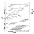
- Fig. 5 shows an in-place mapped schedule in accordance with an embodiment of the present invention.
- Fig. 6 shows a combination of a data locality and an in-place mapped schedule in accordance with a further embodiment of the present invention.
- Fig. 7 shows a representation of a conventional example of a fast transform, more in particular a fast Fourier transform, in which a stage by stage, block by block, butterfly by butterfly scheduling is shown.
- Fig. 8 shows the access graph of a conventional scheduling of the calculation methods in a fast transform according to Fig. 7. Said access graph is not optimal with respect to power consumption and bus loading.
- the present invention presents a method and an apparatus for transforming a first m-dimensional indexed array with N elements into a second m-dimensional indexed array with M elements.
- the first array may be a representation of a physical signal in a telecommunications network or system and the second array represents the transform of this signal or an intermediate array generated as part of a method to obtain the transform.
- the representation of the first array may be formed by indexing time discrete values of a signal into the first array, for example row-by-row, column-column; e.g. by sampling a physical, analog signal.
- telecommunications system any system capable transmitting and receiving signals, such as, but not limited thereto, a computer, a telephone system, a Local Area Network, a Wide Area Network, the Internet, a mobile telecommunications system, a cellular telephone network, a Metropolitan Access Network, a satellite communications system, radio or television.
- the transform may be a fast Fourier transform so that the time domain signal represented by the first array is transformed into the frequency domain representation of the same signal.
- the present invention also includes the reverse process, i.e. from the transformed signal back to a representation of the physical signal. In one example, this would be transforming an array being a representation in the frequency domain to a representation of a time domain signal.
- the present invention deals with applications which can be described by a plurality of code chunks which are substantially equivalent to each other, meaning performing the same operations but with other parameters.
- the application is performed by executing said code chunks in a certain order.
- the code chunks are thus scheduled.
- the applications dealt with in the invention are such that various schedules of said code chunks are acceptable for obtaining the functionality described by said application but no all schedules are acceptable due to data dependencies. Indeed said code chunks read data, modify said data and write said data. In general one can state that code hunks access data.
- the functionality of said application is only realized when the data dependencies inherent to said functionality are respected by the code chunks schedule.
- the present invention presents schedules for such applications and thus exploits the remaining degrees of freedom in said scheduling while respecting the data dependencies.
- the presented schedules are such that when said application is executed on hardware, then the power consumed by said hardware while executing said application is minimized.
- Said hardware can be a general purpose computer with a certain memory structure or a dedicated hardware device, specially designed for said application or a combination thereof.
- the power consumption optimal schedules are selected to have a good data locality, meaning that data produced by a code chunk is consumed as soon as possible by another code chunk.
- said power consumption optimal schedules are selected such that distributed memory configurations in said hardware can be optimally exploited.
- distributed memory configuration is meant a plurality of memories, ordered from small to large memories.
- optimally exploitation of said configuration is meant having more data accesses to smaller memories than to larger memories.
- Power consumption optimisation by combining both data locality improvement and enhanced use of a distributed memory configuration is of course possible.
- the system bus load is reduced. This results in an increase of pure CPU speed because less cache misses and stalls can be expected.
- the invention presents schedules for said type of applications which are more power optimal by using thus either data locality or enhanced use of distributed memory configurations or combination thereof.
- the invention also specifies how data locality is exploited by indicating how data sharing is performed on said hardware.
- the invention also specifies how distributed memory configurations are used.
- code chunks are characterized by the elements of the indexed array accessed by said code chunk.
- the invention is described for code chunks accessing 2 elements, the invention is equally applicable to code chunks accessing more than 2 elements also.
- 1-dimensional indexed arrays the invention is equally applicable to multi-dimensional indexed arrays also.
- the invention deals with applications which perform linear transformations of arrays but which are constructed such that their complexity increases in a logarithmic way with the dimensionality of the arrays treated by the transform. This characteristic is often denoted by stating that a fast transform is meant.
- a non-limiting list of examples of such transformations is the fast Fourier transform, the fast cosine transform, fast Hartly transform and fast Karhunen-Loève transform.
- the invention in particular relates to a Fourier transform application (Fig. 1) wherein a first 1-dimensional data array (1) is transformed into a second 1-dimensional data array (2), being the Fourier transform of said first data array but the invention also applies to similar type of transforms.
- the Fourier transform application can according to the fast Fourier transform approach be represented as a plurality of code chunks, further denoted butterfly codes (3)(4). Said butterfly codes can be scheduled in various ways but certain data dependencies must be respected in order to guarantee that the actual result of executing the code is a Fourier transform.
- An example of a butterfly code reads two elements of said first array and produces two new elements which can overwrite the two elements read.
- the present invention is not limited to two elements being read for the butterfly.
- Said butterfly codes are substantially similar codes because said codes all read a certain number of elements, such as two elements, multiplies one of said read elements with a parameter, adds to said multiplied element the other read element resulting in a first element to write and subtracts said multiplied element from said other read element resulting in a second element.
- said arithmetic operation such as an addition, subtraction and multiplication (or division) operation can be an operation on complex numbers, hence complex operations.
- the multiplication parameter used in said butterfly codes can differ from code to code (it can also be 1).
- the elements accessed can also differ from butterfly code to butterfly code.
- the pair-wise accessing of said codes can be represented as wings, hence the name butterfly code.
- Each of said butterfly code can uniquely be characterized by the elements it accesses, e.g. by the two elements it reads or accesses. For instance, suppose that 1-dimensional data arrays have a length of 32, meaning that these arrays contain 32 elements. Suppose said 32 elements have an index between 0 and 31. One butterfly code would then be characterized as one accessing element 0 and 7 and another butterfly code would then be characterized as the one accessing elements 2 and 3.
- the index difference (6)(7) between the elements access by said butterfly codes is also a characteristic of said butterfly codes.
- the butterfly code accessing elements 0 and 7 has an index difference of 7 while butterfly code accessing elements 2 and 3 has an index difference of 1.
- a first and a second array are identified respectively as the initial data array and the resulting data array, it should be clear that during execution of said butterfly codes intermediate temporary arrays can be identified, for instance, the array obtained after executing the first scheduled butterfly code is different from said first array in the two elements accessed by said butterfly code.
- a plurality of arrays can be identified the butterflies remain characterized by the indexes of the accessed elements as described before. With array variables can be meant both said first, said second and identified intermediate temporary arrays.
- the reference to the element index relates to the functional location of the data of said element in an array and not directly to a location of said data of said element in memory.
- a Fourier transform application can be described as a method for transforming a first N-dimensional array (N may equal 1) into a second N-dimensional array, said second array being the Fourier transform of said first array, said method comprising the steps of executing a plurality of butterfly codes, each code being characterized by the two elements of said array variables it accesses.
- the invention described provides a schedule for executing said butterfly codes.
- a schedule can be represented in a diagram wherein for each butterfly code a single vertical line is drawn at a certain time instance on a horizontal time axis. The endpoints of each line indicate which array elements are accessed.
- the diagram (Fig. 2C) shows the actual schedule (which code is executed when) and the accessing order of said array elements (which elements are accessed when).
- Another representation of certain embodiments of the invention is the structure of the overall code of said application, more in particular the loop structure.
- a data locality optimal scheduling is described. From the plurality of butterfly codes those are selected with a maximal index difference (21) (22) (23), (24), ... and these are put in a first set of maximal index difference butterfly codes. Within this first set, pairs of butterfly codes are created (e.g. pair (21) (22) and pair (23) (24)) and then said pairs of butterfly codes are ordered in a predetermined order (e.g. a bit reversed ordering). Then, for each pair butterfly codes from said plurality of butterfly codes, except the butterfly codes in said first set, are determined, which access at least one array element being accessed also by one of the code of said pair considered.
- a predetermined order e.g. a bit reversed ordering
- the butterfly codes (40)(41) and (50) (51), (52) (53) are selected.
- the horizontal dashed line in Fig. 2C indicates an access relation between butterfly codes.
- These determined butterfly codes are placed in a set, uniquely related to the pair considered.
- the butterfly codes within such a set are then ordered in a tree (60, Fig. 2A).
- the top node (61) of said tree represents either one of said codes of said pair.
- the butterfly codes within such a tree (60) are first ordered according to their index difference. Codes with a high index difference are placed closer to the top node (61) than ones with a lower index difference.
- each index difference a number of codes being a power of 2 are found, said tree will be a binary tree, meaning that each node has two branches.
- the data locality optimal scheduling is then as follows: a pair of codes is selected from said first set according to their predetermined ordering. The codes in said selected pair are executed in a random order. Then the tree is traversed in a depth-first manner and the codes in said binary tree are executed on a traversed node not being executed yet. The execution order of said in a tree ordered codes is thus determined by traversing said binary tree in a depth-first manner. This is illustrated in Fig.
- the presented butterfly schedule has a good data locality and thus good data locality can be exploited now for having a more optimal power consumption when one wants to perform the Fourier transform on a hardware device (75, Fig. 2B).
- a hardware device 75, Fig. 2B
- the data in said arrays are stored in a memory (73), also denoted the main memory, with enough storage place for storing the complete array.
- a traditional execution of the Fourier transform, thus not scheduled as described above, would result in accessing said memory each time when one reads or writes a data element of said array.
- a hardware device however also has one or more registers (71)(72), close to the arithmetic unit (70).
- Said hardware device (75) can have a number of registers by construction or a specialized hardware design can be designed and implemented for said Fourier transform application.
- the number of registers can be selected as part of the design. As only a limited number of registers are usually available and because the storage space of said registers is limited and can not contain the arrays being dealt with in the application completely, temporary storage of array elements in said registers is only useful when good data locality is there, meaning that an element stored in such register by a first butterfly is consumed soon by a second butterfly. With soon is meant before said element is overwritten by yet another butterfly code.
- the time between production of an element and consumption of said element can differ. Indeed the more registers the more time can elapse between production and consumption.
- FIG. 2C illustrates a data sharing possibility in case of a single register between code (21) and (40) while the dashed line (81, Fig. 2C) shows a data sharing possibility between (22) and (52) when a second register is available.
- the execution method described above is such that during said execution of said scheduled codes data is shared between at least part of said pairs of codes subsequently scheduled after one another. Said data sharing is done via registers. Note that the scheduling of said codes results in an access ordering also, meaning an ordering of when a certain element of an array is accessed in function of time.
- Fig. 4 shows a complete diagram of a data locality improved schedule with vertical line referring to code and horizontal lines referring to data sharing possibilities, depending on the amount of register available or made available during custom design.
- scheduling data locality improvement is used completely. Naturally it can be sufficient to have a partial data locality improvement.
- a scheduling having a partial data locality improvement, partial with reference to a traditional implementation is now presented.
- Said scheduling can be formalized as a three loop code wherein the deepest nested loop executes again butterfly code.
- the outer loop is denoted the block code loop
- the second loop is denoted repetitive pattern code
- the deepest nested loop is denoted the lob code loop.
- the number of repetitions of the code is given.
- Said number of repetitions of deeper nested loops is dependent on the number of executions of the code wherein said code is nested.
- the naming of the loops refers to a structure which can be recognized within a scheduling diagram.
- Fig. 3 shows a partial data locality improving schedule wherein blocks (100), repetitive patterns (110) and lobs (120) are indicated. There is a change from one block to another when another pattern appears.
- a repetitive pattern is characterized as a pattern starting with a code having the highest index difference.
- a lob is a butterfly code.
- Characteristic for said partial data locality improvement schedule is also its access ordering. The scheduling of the butterfly codes for this case is determined as follows. Half of the codes (130) with a highest index difference between the two elements in said array accessed by said codes are executed in a predetermined ordering.
- each of said remaining codes separately codes with a index difference being half of the highest index difference and which access at least one array element also being accessed by the remaining code under consideration. Once these codes are determined, they are scheduled together with their related remaining code and executed. This approach generates in the example of Fig. 3 four repetitive patterns (140). After finishing the previous step, still codes with such a highest index difference are not executed. For these the same procedure of determining codes per remaining code is repeated again for the half of these codes but the determined codes selected can have now an index difference being half or a fourth of said highest index difference as shown in the repetitive pattern (110).
- the lowest considered index difference equals the highest index divided by 2 to the power the number of repetitions of said step.
- the determined codes are related to each other because a code with a lower index difference accesses an array element at least being accessed by a code having a higher index difference. Note that the data locality is improved thus data sharing via registers is possible. As an example one can share element 0 between the last code of the sequence (100) and the first of the sequence of repetitive patterns of type (140) if one register is available. When a second register is available in the hardware device, one can share values between codes which are separated by one other code execution, such as the last code of sequence (100) and the second code of the first repetitive pattern of type (140).
- a scheduling allowing power optimal use of distributed memory configurations are presented.
- Said distributed memory configurations are residing in the hardware device on which the optimal scheduled application is executed.
- the Fourier transform application accesses arrays.
- distributed memory configuration is meant here a plurality of memories containing a least a temporarily memory with a size not being capable to store the complete array and another memory at least capable for storing said arrays.
- the latter memory can be denoted the main memory.
- the notion temporarily denotes that data stored within said memory can only temporarily resides there during execution of said application, thus transfers of data between such a temporarily memory and the main memory are needed.
- an in-place scheduling or mapping Said schedule must however respect the data dependencies of said application.
- the use of a single temporarily memory is in the distributed memory configuration.
- the application comprises of code chunks, each being characterized by the elements of the arrays they access.
- the application is executed by executing each of said code chunks according to a predetermined schedule.
- Optimal use of a distributed memory configuration can be obtained by grouping code chunks which access nearby elements in said array variables. With “nearby” is meant having an index being within a certain range. For instance a code chunk addressing elements 0 and 7 and another code chunk addressing elements 1 and 2 are within a range of length 8.
- arrays of length 32 are used. In the invention one groups said code chunks of length less than the length of said arrays such that groups of code chunks accessing nearby elements are created.
- Fig. 5 shows an in-place scheduling as an example of an embodiment of the present invention. For the first two stages a conventional scheduling is used.
- the remaining code chunks are scheduled.
- the in-place scheduling approach is extended to a distributed memory configuration with a plurality of temporarily memories.
- a first grouping wherein codes accessing array elements having a range 0-15 are grouped in a first group and codes accessing array elements having a range 16-31 are grouped in a second group.
- a further grouping can be performed, for instance, grouping codes within a range 0-7 and 8-15 in a first subgroup and a second subgroup.
- a similar grouping is performed in said second grouping.
- execution of said application groupwise can exploit two memories. In the example that would be a first memory at least being capable of storing 16 array elements and a second memory at least being capable of storing 8 array elements.
- the relation to the memories should be considered per group size.
- group size is meant here the maximal index difference between indexes of elements of said arrays being accessed by the codes within a group.
- codes within one group group related to range 0-15 or the group related to range 16-31) exploit the same memory (the memory with minimal size 16). The same can be stated for subgroups.
- This approach of having groups with different group sizes and related memories with different minimal memory sizes but smaller than the main memory or at least not capable of storing the arrays completely can be used for more than two group and memory sizes of course.
- Characteristic for the in-place scheduled code chunks is that codes accessing nearby elements in said array variables are scheduled nearby in time. With nearby elements is meant having a small difference between their index.
- the first embodiment can be denoted as a schedule exploiting a partial in-place mapping while the second embodiment suggests performing a more extensive in-place mapping over several levels.
- the benefits of in-place mapping versus the drawbacks such as more memories must be considered in deciding how many levels one wants to consider.
- the hardware limitations of the device one wants to use must be taken into account when no custom design of said hardware device is possible. It must be emphasized that in-place mapping (complete or partial) is combinable with data locality improvement approaches (complete or partial).
- Fig. 6 shows a mixed data locality and in-place approach.
- the applications dealt with by the invention have as characteristic that the calculation method steps or butterfly codes can be labeled according to the maximal index difference between the indexes of the elements of the arrays they access. It is a further characteristic that the data dependencies of said fast transform application require that most of the butterfly codes with a high index difference must be executed in the beginning of the schedule while most of the butterfly codes with a lower index difference are scheduled at the end of the schedule. While in the prior art the data dependencies are respected because schedules are used which execute all butterfly codes with a high index difference before codes with a lower index difference are executed, it is the contribution of the invention that the scheduling freedom, which still remain even when data dependencies exist, is exploited.
- this scheduling freedom is not only exploited for the last codes that must be executed but for a substantially part of the codes defining the application.
- a spreading of codes with a variety of index differences over the time schedule for executing said application is performed.
- the term maximal should be replaced by minimal and non-maximal should be replaced by non-minimal.
- the ordering in said binary trees is then from lower to higher index differences.
- said butterfly codes are characterized by an index difference being with a range between a minimal index difference and a maximal index difference, i.e. always an extreme difference.
- These minimal index differences and maximal index differences define range boundaries.
- the applications are characterized in that one traverses mainly through said codes from one of said boundary to another of said boundary. One can thus define one of said boundaries to be the starting index boundary and the remaining boundary the finishing index boundary.
- a method for transforming a first m-dimensional indexed array into a second m-dimensional indexed array comprising the steps of executing a plurality of butterfly codes, each butterfly code being characterized by the elements of the indexed array accessed by said butterfly code, said execution being characterized in that at least part of said butterfly codes are assigned to at least one group and butterfly codes within a group are scheduled sequentially, said assignment of butterfly codes to a group comprises of a first selection step wherein from the set of butterfly codes with a index difference between the elements of the array accessed by said butterfly codes being equal to the starting index boundary a plurality of butterfly codes are selected and a second selection step wherein from the set of butterfly codes with a non-boundary index difference between the elements of the array accessed by said butterfly codes a plurality of butterfly codes which access at least one element of an array also being accessed by one of said plurality of butterfly codes selected by said first selection step are selected and assigning said butterfly codes determined by said first selection step and said
Landscapes
- Physics & Mathematics (AREA)
- Mathematical Physics (AREA)
- Engineering & Computer Science (AREA)
- General Physics & Mathematics (AREA)
- Computational Mathematics (AREA)
- Mathematical Analysis (AREA)
- Mathematical Optimization (AREA)
- Pure & Applied Mathematics (AREA)
- Data Mining & Analysis (AREA)
- Theoretical Computer Science (AREA)
- Discrete Mathematics (AREA)
- Algebra (AREA)
- Databases & Information Systems (AREA)
- Software Systems (AREA)
- General Engineering & Computer Science (AREA)
- Complex Calculations (AREA)
Abstract
Description
| 0 | 0 | 1 |
| 1 | 8 | 2 |
| 4 | 4 | 1 |
| 5 | 12 | 3 |
| 12 | 2 | 1 |
| 13 | 10 | 2 |
| 16 | 6 | 1 |
| 17 | 14 | 4 |
| 32 | 1 | 1 |
| 33 | 9 | 2 |
| 36 | 5 | 1 |
| 37 | 13 | 3 |
| 44 | 3 | 1 |
| 45 | 11 | 2 |
| 48 | 7 | 1 |
| 49 | 14 | 5 |
A method for transforming a first m-dimensional array into a second m-dimensional array, said second array being the Fourier transform of said first array, said method comprising the steps of executing a plurality of butterfly codes, each butterfly code being characterized by the elements of the array accessed by said butterfly code, said execution is characterized in that said butterfly codes are scheduled as follows:
from said butterfly codes those butterfly codes with a maximal index difference between the elements of the array accessed by said codes are selected and grouped in pairs and placed in a predetermined ordering.
For each pair of said selected and ordered butterfly codes, butterfly codes which access at least one element of said arrays being accessed also by one of the butterfly codes of a pair are determined and assigned to said pair.
For each pair of said selected and ordered butterfly codes, the assigned butterfly codes are ordered in a binary tree with as top node one butterfly code of said pair according to the index difference between the elements of the array accessed by said butterfly code and determining the execution order of said assigned butterfly codes by traversing said binary tree in a depth-first manner. A higher index difference of such butterfly code implies closer placement to the top node of said tree.
A method for transforming a first m-dimensional indexed array with N elements into a second m-dimensional indexed array with N elements, said second array being a fast transform of said first array, said method comprising the steps of executing a plurality of butterfly codes, each butterfly code being characterized by the elements of the indexed arrays accessed by said butterfly code, said execution is characterized in that at least part of said butterfly codes are scheduled such that butterfly codes accessing elements of said arrays with an index difference between said elements smaller than a threshold value being at most N/p with p an integer being larger than 1 are assigned to a group, butterfly codes within one group are executed sequentially before executing butterfly codes of another group. Said execution of said groups of butterfly codes accesses only a first memory with a storage space for less than N elements.
A method for transforming a first m-dimensional indexed array into a second m-dimensional indexed array, said method comprising the steps of executing a plurality of butterfly codes, each butterfly code being characterized by the elements of the indexed array accessed by said butterfly code, said execution being characterized in that at least part of said butterfly codes are assigned to at least one group and butterfly codes within a group are scheduled sequentially, said assignment of butterfly codes to a group comprises of a first selection step wherein from the set of butterfly codes with a index difference between the elements of the array accessed by said butterfly codes being equal to the starting index boundary a plurality of butterfly codes are selected and a second selection step wherein from the set of butterfly codes with a non-boundary index difference between the elements of the array accessed by said butterfly codes a plurality of butterfly codes which access at least one element of an array also being accessed by one of said plurality of butterfly codes selected by said first selection step are selected and assigning said butterfly codes determined by said first selection step and said second selection step to one group.
Claims (20)
- A method for transforming a first m-dimensional indexed array into a second m-dimensional indexed array, said method comprising the steps of executing a plurality of butterfly codes, each butterfly code being characterized by the elements of an indexed array accessed by said butterfly code, said execution being characterized in that at least part of said butterfly codes are assigned to at least one group and butterfly codes within a group are scheduled sequentially, said assignment of butterfly codes to a group comprises a first selection step wherein from the set of butterfly codes with a maximal index difference between the elements of the array accessed by said butterfly code, a plurality of butterfly codes are selected and a second selection step wherein from the set of butterfly codes with a non-maximal index difference between the elements of the array accessed by said butterfly codes a plurality of butterfly codes which access at least one element of an array also being accessed by one of said plurality of butterfly codes selected by said first selection step are selected and assigning said butterfly codes determined by said first selection step and said second selection step to one group.
- The method recited in claim 1, wherein said second array is a Fourier transform of said first array.
- The method recited in claim 1 or 2, wherein for at least one group, scheduling of butterfly codes assigned to said group is based on a depth-first traversing of a binary tree, wherein butterfly codes with a more extreme index difference between the elements of the arrays accessed are placed closer to the top node of said binary tree.
- The method recited in any previous claim, wherein during said execution of said scheduled butterfly codes at least part of the accesses of elements accessed by said scheduled butterfly codes are accesses to storage spaces being capable of storing a single element.
- The method recited in any previous claim wherein m is 1.
- The method according to any previous claim, wherein the first m-dimensional indexed array is a representation of a physical signal in a telecommunications system or a transform thereof.
- A processing engine for transforming a first m-dimensional indexed array into a second m-dimensional indexed array, the engine having means for executing a plurality of butterfly codes, each butterfly code being characterized by the elements of an indexed array accessed by said butterfly code, said execution being characterized in that at least part of said butterfly codes are assigned to at least one group and butterfly codes within a group are scheduled sequentially, said assignment of butterfly codes to a group comprises a first selection step wherein from the set of butterfly codes with a maximal index difference between the elements of the array accessed by said butterfly code, a plurality of butterfly codes are selected and a second selection step wherein from the set of butterfly codes with a non-maximal index difference between the elements of the array accessed by said butterfly codes a plurality of butterfly codes which access at least one element of an array also being accessed by one of said plurality of butterfly codes selected by said first selection step are selected and assigning said butterfly codes determined by said first selection step and said second selection step to one group.
- A method for transforming a first m-dimensional indexed array of length N into a second m-dimensional indexed array of length N, said method comprising the steps of executing a plurality of butterfly codes, each butterfly code being characterized by the elements of an indexed array accessed by said butterfly code, said method is characterized in that at least part of said butterfly codes are assigned to at least one group of butterfly codes such that butterfly codes within a group are butterfly codes access elements of said arrays with an index difference between said elements smaller than a group-specific threshold value being at most N/p with p an integer being larger than 1, butterfly codes within one group are executed sequentially.
- The method according to claim 8 wherein during execution of said butterfly codes within a group only a group-specific memory with a minimal storage space being determined by said group-specific threshold value for that group is accessed.
- The method recited in claim 8 or 9 wherein said second array being the Fourier transform of said first array.
- The method recited in any of the claims 8 to 10 wherein said integer p is 2.
- The method recited in any of the claims 8 to 11 wherein m is 1.
- The method recited in any of the claims 8 to 12 wherein for a part of said groups, butterfly codes within one group are executed sequentially before executing butterfly codes of another group.
- The method recited in any of the claims 8 to 12, wherein for a part of said groups butterfly codes within one group are executed in parallel with the execution of butterfly codes of another group.
- The method recited in 14, wherein after finishing execution of a group of butterfly codes, data is transferred between the group-specific memory of said group and a memory being specific for a group with a larger group-specific threshold value or a memory with a storage space for at least N elements.
- The method according to any of the claims 8 to 15, wherein the first m-dimensional indexed array of length N is a representation of a physical signal or a transform thereof.
- A processing engine for transforming a first m-dimensional indexed array into a second m-dimensional indexed array, the engine having means executing a plurality of butterfly codes, each butterfly code being characterized by the elements of an indexed array accessed by said butterfly code, said method is characterized in that at least part of said butterfly codes are assigned to at least one group of butterfly codes such that butterfly codes within a group are butterfly codes access elements of said arrays with an index difference between said elements smaller than a group-specific threshold value being at most N/p with p an integer being larger than 1, butterfly codes within one group are executed sequentially.
- The processing engine according to claim 17 further comprising a group specific memory with a minimal storage space being determined by said group-specific threshold value for that group, wherein the processing engine is adapted so that during execution of said butterfly codes within a group only the group-specific memory is accessed.
- A computer program product for execution on a computer, the computer program product executing a method according to claims 1 to 6 or claims 8 to 16.
- The computer program product according to claim 19 stored on a computer readable data carrier.
Applications Claiming Priority (2)
| Application Number | Priority Date | Filing Date | Title |
|---|---|---|---|
| US14307399P | 1999-07-09 | 1999-07-09 | |
| US143073P | 1999-07-09 |
Publications (2)
| Publication Number | Publication Date |
|---|---|
| EP1067464A2 true EP1067464A2 (en) | 2001-01-10 |
| EP1067464A3 EP1067464A3 (en) | 2012-03-07 |
Family
ID=22502482
Family Applications (1)
| Application Number | Title | Priority Date | Filing Date |
|---|---|---|---|
| EP00870161A Withdrawn EP1067464A3 (en) | 1999-07-09 | 2000-07-10 | Method and apparatus for fast fourier transform calculation |
Country Status (2)
| Country | Link |
|---|---|
| US (1) | US6591284B1 (en) |
| EP (1) | EP1067464A3 (en) |
Families Citing this family (9)
| Publication number | Priority date | Publication date | Assignee | Title |
|---|---|---|---|---|
| US6963891B1 (en) * | 1999-04-08 | 2005-11-08 | Texas Instruments Incorporated | Fast fourier transform |
| US6609140B1 (en) * | 1999-11-30 | 2003-08-19 | Mercury Computer Systems, Inc. | Methods and apparatus for fast fourier transforms |
| US6817017B2 (en) * | 2000-04-24 | 2004-11-09 | Leotel, Technologies, Inc. | Universal interface system |
| US6990061B2 (en) * | 2000-05-31 | 2006-01-24 | Interuniversitair Micro-Elektronica Centrum | Method and apparatus for channel estimation |
| JP2002351858A (en) * | 2001-05-30 | 2002-12-06 | Fujitsu Ltd | Processing equipment |
| US20030050944A1 (en) * | 2001-08-21 | 2003-03-13 | Olivier Gay-Bellile | Device for computing discrete transforms |
| US7029812B2 (en) * | 2002-10-25 | 2006-04-18 | Samsung Electronics Co., Ltd. | Organophotoreceptor with charge transport compound having an epoxy group |
| US7454452B2 (en) * | 2003-03-25 | 2008-11-18 | Texas Instruments Incorporated | Fast fourier transform operation with reduced cache penalty |
| JP2006331186A (en) * | 2005-05-27 | 2006-12-07 | Ffc Ltd | FFT operation device and FFT operation method |
-
2000
- 2000-07-10 EP EP00870161A patent/EP1067464A3/en not_active Withdrawn
- 2000-07-10 US US09/613,181 patent/US6591284B1/en not_active Expired - Lifetime
Non-Patent Citations (3)
| Title |
|---|
| BAAS B M: "A low-power, high-performance, 1024-point FFT processor", IEEE JOURNAL OF SOLID-STATE CIRCUITS, IEEE SERVICE CENTER, PISCATAWAY, NJ, USA, vol. 34, no. 3, March 1999 (1999-03), XP011060956, ISSN: 0018-9200 * |
| BROCKMEYER E ET AL: "Code transformations for reduced data transfer and storage in low power realization of DAB synchro core", PATMOS'99 INTERNATIONAL WORKSHOP ON POWER AND TIMING MODELING, OPTIMIZATION AND SIMULATION, 6-8 OCTOBER 1999, KOS, GREECE, October 1999 (1999-10), XP55017345, * |
| BROCKMEYER E ET AL: "Parametrizable behavioral IP module for a data-localized low-power FFT", 1999 IEEE WORKSHOP ON SIGNAL PROCESSING SYSTEMS (SIPS 99), 20-22 OCTOBER 1999, TAIPEI, TAIWAN, October 1999 (1999-10), pages 635-644, XP010370847, DOI: 10.1109/SIPS.1999.822370 ISBN: 978-0-7803-5650-4 * |
Also Published As
| Publication number | Publication date |
|---|---|
| US6591284B1 (en) | 2003-07-08 |
| EP1067464A3 (en) | 2012-03-07 |
Similar Documents
| Publication | Publication Date | Title |
|---|---|---|
| US6968440B2 (en) | Systems and methods for processor memory allocation | |
| Willard | New trie data structures which support very fast search operations | |
| US6473774B1 (en) | Method and apparatus for record addressing in partitioned files | |
| US5179699A (en) | Partitioning of sorted lists for multiprocessors sort and merge | |
| US7085769B1 (en) | Method and apparatus for performing hash join | |
| KR100260868B1 (en) | Computer systems and methods for sorting array elements to optimize array changes | |
| GB2406679A (en) | Index tree structure and key compression for a database | |
| US7640284B1 (en) | Bit reversal methods for a parallel processor | |
| US6735600B1 (en) | Editing protocol for flexible search engines | |
| CN1292903A (en) | Method and access means for determining storage address of data value in memory device | |
| US6591284B1 (en) | Method for performing a fast transform | |
| US20040049630A1 (en) | Implementation of a content addressable memory using a ram-cell structure | |
| US6745198B1 (en) | Parallel spatial join index | |
| CN115203211B (en) | A method and system for generating unique hash serial numbers | |
| KR20000027489A (en) | Method of inserting higher dimension index structure | |
| CN116521611B (en) | A generalized architecture design method for deep learning processors | |
| US8023401B2 (en) | Apparatus and method for fast fourier transform/inverse fast fourier transform | |
| KR100825771B1 (en) | Fast Fourier Transform Processor and its Method for Half-Memory | |
| JP2000066872A (en) | Bit and digit reversing method | |
| Ahuja et al. | An associative/parallel processor for partial match retrieval using superimposed codes | |
| Böhm et al. | Efficient bulk loading of large high-dimensional indexes | |
| CN116756253B (en) | Data storage and query methods, devices, equipment and media of relational database | |
| US7096462B2 (en) | System and method for using data address sequences of a program in a software development tool | |
| Thomborson et al. | Rectilinear Steiner tree minimization on a workstation | |
| Hermann et al. | Engineering minimal k-perfect hash functions |
Legal Events
| Date | Code | Title | Description |
|---|---|---|---|
| PUAI | Public reference made under article 153(3) epc to a published international application that has entered the european phase |
Free format text: ORIGINAL CODE: 0009012 |
|
| AK | Designated contracting states |
Kind code of ref document: A2 Designated state(s): AT BE CH CY DE DK ES FI FR GB GR IE IT LI LU MC NL PT SE |
|
| AX | Request for extension of the european patent |
Free format text: AL;LT;LV;MK;RO;SI |
|
| RIN1 | Information on inventor provided before grant (corrected) |
Inventor name: D'EER, JOHAN Inventor name: GHEZ, CEDRIC Inventor name: CATTHOOR, FRANCKY Inventor name: BROCKMEYER, ERIC |
|
| RAP1 | Party data changed (applicant data changed or rights of an application transferred) |
Owner name: IMEC |
|
| PUAL | Search report despatched |
Free format text: ORIGINAL CODE: 0009013 |
|
| AK | Designated contracting states |
Kind code of ref document: A3 Designated state(s): AT BE CH CY DE DK ES FI FR GB GR IE IT LI LU MC NL PT SE |
|
| AX | Request for extension of the european patent |
Extension state: AL LT LV MK RO SI |
|
| RIC1 | Information provided on ipc code assigned before grant |
Ipc: G06F 17/14 20060101AFI20120127BHEP |
|
| STAA | Information on the status of an ep patent application or granted ep patent |
Free format text: STATUS: THE APPLICATION IS DEEMED TO BE WITHDRAWN |
|
| 18D | Application deemed to be withdrawn |
Effective date: 20120201 |