EP1067441A1 - An intermediate medium for transferring a toner image from an imaging medium to a final receiving material - Google Patents
An intermediate medium for transferring a toner image from an imaging medium to a final receiving material Download PDFInfo
- Publication number
- EP1067441A1 EP1067441A1 EP20000202202 EP00202202A EP1067441A1 EP 1067441 A1 EP1067441 A1 EP 1067441A1 EP 20000202202 EP20000202202 EP 20000202202 EP 00202202 A EP00202202 A EP 00202202A EP 1067441 A1 EP1067441 A1 EP 1067441A1
- Authority
- EP
- European Patent Office
- Prior art keywords
- rubber
- pfpe
- intermediate medium
- medium according
- ocf
- Prior art date
- Legal status (The legal status is an assumption and is not a legal conclusion. Google has not performed a legal analysis and makes no representation as to the accuracy of the status listed.)
- Granted
Links
- 238000003384 imaging method Methods 0.000 title claims abstract description 16
- 239000000463 material Substances 0.000 title description 11
- 229920001971 elastomer Polymers 0.000 claims abstract description 81
- 239000005060 rubber Substances 0.000 claims abstract description 81
- 229920001940 conductive polymer Polymers 0.000 claims abstract description 24
- 239000004020 conductor Substances 0.000 claims abstract description 15
- 150000001875 compounds Chemical class 0.000 claims abstract description 13
- 229920000642 polymer Polymers 0.000 claims abstract description 10
- 229920000767 polyaniline Polymers 0.000 claims description 42
- 239000003921 oil Substances 0.000 claims description 36
- PAYRUJLWNCNPSJ-UHFFFAOYSA-N Aniline Chemical compound NC1=CC=CC=C1 PAYRUJLWNCNPSJ-UHFFFAOYSA-N 0.000 claims description 33
- 239000010702 perfluoropolyether Substances 0.000 claims description 31
- 229920001577 copolymer Polymers 0.000 claims description 24
- NIXOWILDQLNWCW-UHFFFAOYSA-M acrylate group Chemical group C(C=C)(=O)[O-] NIXOWILDQLNWCW-UHFFFAOYSA-M 0.000 claims description 12
- 125000003118 aryl group Chemical group 0.000 claims description 8
- 150000001732 carboxylic acid derivatives Chemical class 0.000 claims description 8
- 125000003178 carboxy group Chemical group [H]OC(*)=O 0.000 claims description 3
- 230000005855 radiation Effects 0.000 abstract description 6
- 239000007858 starting material Substances 0.000 abstract description 6
- 229920001519 homopolymer Polymers 0.000 description 29
- 238000012546 transfer Methods 0.000 description 26
- 239000000243 solution Substances 0.000 description 19
- 238000006243 chemical reaction Methods 0.000 description 17
- OKTJSMMVPCPJKN-UHFFFAOYSA-N Carbon Chemical compound [C] OKTJSMMVPCPJKN-UHFFFAOYSA-N 0.000 description 14
- VEXZGXHMUGYJMC-UHFFFAOYSA-N Hydrochloric acid Chemical compound Cl VEXZGXHMUGYJMC-UHFFFAOYSA-N 0.000 description 12
- 239000002904 solvent Substances 0.000 description 12
- 239000000203 mixture Substances 0.000 description 11
- 239000011541 reaction mixture Substances 0.000 description 11
- 238000000034 method Methods 0.000 description 10
- 230000008569 process Effects 0.000 description 10
- BYEAHWXPCBROCE-UHFFFAOYSA-N 1,1,1,3,3,3-hexafluoropropan-2-ol Chemical compound FC(F)(F)C(O)C(F)(F)F BYEAHWXPCBROCE-UHFFFAOYSA-N 0.000 description 9
- 238000005259 measurement Methods 0.000 description 9
- 239000012071 phase Substances 0.000 description 9
- 230000015572 biosynthetic process Effects 0.000 description 8
- 239000006232 furnace black Substances 0.000 description 8
- 238000003756 stirring Methods 0.000 description 8
- 101100269308 Saccharomyces cerevisiae (strain ATCC 204508 / S288c) PFS1 gene Proteins 0.000 description 7
- 235000019395 ammonium persulphate Nutrition 0.000 description 7
- 239000000178 monomer Substances 0.000 description 7
- 239000000843 powder Substances 0.000 description 7
- 239000004160 Ammonium persulphate Substances 0.000 description 6
- ROOXNKNUYICQNP-UHFFFAOYSA-N ammonium persulfate Chemical compound [NH4+].[NH4+].[O-]S(=O)(=O)OOS([O-])(=O)=O ROOXNKNUYICQNP-UHFFFAOYSA-N 0.000 description 6
- 238000001723 curing Methods 0.000 description 6
- 238000002474 experimental method Methods 0.000 description 6
- RVZRBWKZFJCCIB-UHFFFAOYSA-N perfluorotributylamine Chemical compound FC(F)(F)C(F)(F)C(F)(F)C(F)(F)N(C(F)(F)C(F)(F)C(F)(F)C(F)(F)F)C(F)(F)C(F)(F)C(F)(F)C(F)(F)F RVZRBWKZFJCCIB-UHFFFAOYSA-N 0.000 description 6
- 239000003054 catalyst Substances 0.000 description 5
- LQNUZADURLCDLV-UHFFFAOYSA-N nitrobenzene Chemical compound [O-][N+](=O)C1=CC=CC=C1 LQNUZADURLCDLV-UHFFFAOYSA-N 0.000 description 5
- -1 polyoxymethylene Polymers 0.000 description 5
- 229920002379 silicone rubber Polymers 0.000 description 5
- 238000003786 synthesis reaction Methods 0.000 description 5
- XLYOFNOQVPJJNP-UHFFFAOYSA-N water Substances O XLYOFNOQVPJJNP-UHFFFAOYSA-N 0.000 description 5
- 238000005160 1H NMR spectroscopy Methods 0.000 description 4
- WEVYAHXRMPXWCK-UHFFFAOYSA-N acetonitrile Substances CC#N WEVYAHXRMPXWCK-UHFFFAOYSA-N 0.000 description 4
- 150000001448 anilines Chemical group 0.000 description 4
- 239000008346 aqueous phase Substances 0.000 description 4
- 230000008901 benefit Effects 0.000 description 4
- 229910052799 carbon Inorganic materials 0.000 description 4
- 239000002019 doping agent Substances 0.000 description 4
- 125000004433 nitrogen atom Chemical group N* 0.000 description 4
- 229920000128 polypyrrole Polymers 0.000 description 4
- 229920000123 polythiophene Polymers 0.000 description 4
- 238000002360 preparation method Methods 0.000 description 4
- 229920005989 resin Polymers 0.000 description 4
- 239000011347 resin Substances 0.000 description 4
- 238000006467 substitution reaction Methods 0.000 description 4
- 238000010276 construction Methods 0.000 description 3
- 238000010438 heat treatment Methods 0.000 description 3
- 229910052751 metal Inorganic materials 0.000 description 3
- 239000002184 metal Substances 0.000 description 3
- 239000002245 particle Substances 0.000 description 3
- 229920000515 polycarbonate Polymers 0.000 description 3
- 239000004417 polycarbonate Substances 0.000 description 3
- 239000002243 precursor Substances 0.000 description 3
- 238000010992 reflux Methods 0.000 description 3
- 150000003839 salts Chemical class 0.000 description 3
- 239000000758 substrate Substances 0.000 description 3
- 238000001029 thermal curing Methods 0.000 description 3
- NWZSZGALRFJKBT-KNIFDHDWSA-N (2s)-2,6-diaminohexanoic acid;(2s)-2-hydroxybutanedioic acid Chemical compound OC(=O)[C@@H](O)CC(O)=O.NCCCC[C@H](N)C(O)=O NWZSZGALRFJKBT-KNIFDHDWSA-N 0.000 description 2
- CSCPPACGZOOCGX-UHFFFAOYSA-N Acetone Chemical compound CC(C)=O CSCPPACGZOOCGX-UHFFFAOYSA-N 0.000 description 2
- KAKZBPTYRLMSJV-UHFFFAOYSA-N Butadiene Chemical compound C=CC=C KAKZBPTYRLMSJV-UHFFFAOYSA-N 0.000 description 2
- 238000000023 Kugelrohr distillation Methods 0.000 description 2
- 238000005481 NMR spectroscopy Methods 0.000 description 2
- PPBRXRYQALVLMV-UHFFFAOYSA-N Styrene Chemical compound C=CC1=CC=CC=C1 PPBRXRYQALVLMV-UHFFFAOYSA-N 0.000 description 2
- 230000002378 acidificating effect Effects 0.000 description 2
- 230000004913 activation Effects 0.000 description 2
- 150000001450 anions Chemical class 0.000 description 2
- 239000002585 base Substances 0.000 description 2
- 239000003795 chemical substances by application Substances 0.000 description 2
- 229920000775 emeraldine polymer Polymers 0.000 description 2
- 125000005843 halogen group Chemical group 0.000 description 2
- IKDUDTNKRLTJSI-UHFFFAOYSA-N hydrazine monohydrate Substances O.NN IKDUDTNKRLTJSI-UHFFFAOYSA-N 0.000 description 2
- 239000012535 impurity Substances 0.000 description 2
- 239000007788 liquid Substances 0.000 description 2
- 238000002844 melting Methods 0.000 description 2
- 229910044991 metal oxide Inorganic materials 0.000 description 2
- 150000004706 metal oxides Chemical class 0.000 description 2
- 238000002156 mixing Methods 0.000 description 2
- 229910052757 nitrogen Inorganic materials 0.000 description 2
- 239000012299 nitrogen atmosphere Substances 0.000 description 2
- LPNYRYFBWFDTMA-UHFFFAOYSA-N potassium tert-butoxide Chemical compound [K+].CC(C)(C)[O-] LPNYRYFBWFDTMA-UHFFFAOYSA-N 0.000 description 2
- 239000000523 sample Substances 0.000 description 2
- 239000004945 silicone rubber Substances 0.000 description 2
- 239000000126 substance Substances 0.000 description 2
- 238000011282 treatment Methods 0.000 description 2
- PWKNBLFSJAVFAB-UHFFFAOYSA-N 1-fluoro-2-nitrobenzene Chemical compound [O-][N+](=O)C1=CC=CC=C1F PWKNBLFSJAVFAB-UHFFFAOYSA-N 0.000 description 1
- VEXZGXHMUGYJMC-UHFFFAOYSA-M Chloride anion Chemical compound [Cl-] VEXZGXHMUGYJMC-UHFFFAOYSA-M 0.000 description 1
- 239000004593 Epoxy Substances 0.000 description 1
- VGGSQFUCUMXWEO-UHFFFAOYSA-N Ethene Chemical compound C=C VGGSQFUCUMXWEO-UHFFFAOYSA-N 0.000 description 1
- 239000005977 Ethylene Substances 0.000 description 1
- VTLYFUHAOXGGBS-UHFFFAOYSA-N Fe3+ Chemical compound [Fe+3] VTLYFUHAOXGGBS-UHFFFAOYSA-N 0.000 description 1
- 239000002033 PVDF binder Substances 0.000 description 1
- 229930040373 Paraformaldehyde Natural products 0.000 description 1
- 239000004952 Polyamide Substances 0.000 description 1
- 239000004698 Polyethylene Substances 0.000 description 1
- 229920000265 Polyparaphenylene Polymers 0.000 description 1
- 239000004721 Polyphenylene oxide Substances 0.000 description 1
- 239000004743 Polypropylene Substances 0.000 description 1
- 239000004793 Polystyrene Substances 0.000 description 1
- UCKMPCXJQFINFW-UHFFFAOYSA-N Sulphide Chemical compound [S-2] UCKMPCXJQFINFW-UHFFFAOYSA-N 0.000 description 1
- 239000004809 Teflon Substances 0.000 description 1
- 229920006362 Teflon® Polymers 0.000 description 1
- 238000003848 UV Light-Curing Methods 0.000 description 1
- 239000002253 acid Substances 0.000 description 1
- HFBMWMNUJJDEQZ-UHFFFAOYSA-N acryloyl chloride Chemical compound ClC(=O)C=C HFBMWMNUJJDEQZ-UHFFFAOYSA-N 0.000 description 1
- 239000000853 adhesive Substances 0.000 description 1
- 230000001070 adhesive effect Effects 0.000 description 1
- 230000002411 adverse Effects 0.000 description 1
- 229910052783 alkali metal Inorganic materials 0.000 description 1
- 229910000272 alkali metal oxide Inorganic materials 0.000 description 1
- HSFWRNGVRCDJHI-UHFFFAOYSA-N alpha-acetylene Natural products C#C HSFWRNGVRCDJHI-UHFFFAOYSA-N 0.000 description 1
- 125000002490 anilino group Chemical group [H]N(*)C1=C([H])C([H])=C([H])C([H])=C1[H] 0.000 description 1
- 230000001588 bifunctional effect Effects 0.000 description 1
- 229920001400 block copolymer Polymers 0.000 description 1
- 230000008859 change Effects 0.000 description 1
- 150000001805 chlorine compounds Chemical class 0.000 description 1
- 238000004140 cleaning Methods 0.000 description 1
- XLJMAIOERFSOGZ-UHFFFAOYSA-M cyanate Chemical compound [O-]C#N XLJMAIOERFSOGZ-UHFFFAOYSA-M 0.000 description 1
- 230000007423 decrease Effects 0.000 description 1
- 230000007812 deficiency Effects 0.000 description 1
- 230000000694 effects Effects 0.000 description 1
- 239000003792 electrolyte Substances 0.000 description 1
- 125000003700 epoxy group Chemical group 0.000 description 1
- 239000000945 filler Substances 0.000 description 1
- 229910052731 fluorine Inorganic materials 0.000 description 1
- 125000001153 fluoro group Chemical group F* 0.000 description 1
- 125000003709 fluoroalkyl group Chemical group 0.000 description 1
- 229910002804 graphite Inorganic materials 0.000 description 1
- 239000010439 graphite Substances 0.000 description 1
- 150000004820 halides Chemical class 0.000 description 1
- 239000012943 hotmelt Substances 0.000 description 1
- 125000002887 hydroxy group Chemical group [H]O* 0.000 description 1
- 238000011065 in-situ storage Methods 0.000 description 1
- 238000002347 injection Methods 0.000 description 1
- 239000007924 injection Substances 0.000 description 1
- 230000003993 interaction Effects 0.000 description 1
- 239000012948 isocyanate Substances 0.000 description 1
- IQPQWNKOIGAROB-UHFFFAOYSA-N isocyanate group Chemical group [N-]=C=O IQPQWNKOIGAROB-UHFFFAOYSA-N 0.000 description 1
- 239000011159 matrix material Substances 0.000 description 1
- 230000007246 mechanism Effects 0.000 description 1
- 238000012986 modification Methods 0.000 description 1
- 230000004048 modification Effects 0.000 description 1
- FYJQJMIEZVMYSD-UHFFFAOYSA-N perfluoro-2-butyltetrahydrofuran Chemical compound FC(F)(F)C(F)(F)C(F)(F)C(F)(F)C1(F)OC(F)(F)C(F)(F)C1(F)F FYJQJMIEZVMYSD-UHFFFAOYSA-N 0.000 description 1
- 239000004014 plasticizer Substances 0.000 description 1
- 229920001197 polyacetylene Polymers 0.000 description 1
- 229920000058 polyacrylate Polymers 0.000 description 1
- 229920002647 polyamide Polymers 0.000 description 1
- 229920000728 polyester Polymers 0.000 description 1
- 239000004645 polyester resin Substances 0.000 description 1
- 229920001225 polyester resin Polymers 0.000 description 1
- 229920000573 polyethylene Polymers 0.000 description 1
- 238000006116 polymerization reaction Methods 0.000 description 1
- 229920006324 polyoxymethylene Polymers 0.000 description 1
- 229920006380 polyphenylene oxide Polymers 0.000 description 1
- 229920001155 polypropylene Polymers 0.000 description 1
- 229920002223 polystyrene Polymers 0.000 description 1
- 229920002635 polyurethane Polymers 0.000 description 1
- 239000004814 polyurethane Substances 0.000 description 1
- 229920002981 polyvinylidene fluoride Polymers 0.000 description 1
- 239000011148 porous material Substances 0.000 description 1
- QQONPFPTGQHPMA-UHFFFAOYSA-N propylene Natural products CC=C QQONPFPTGQHPMA-UHFFFAOYSA-N 0.000 description 1
- 125000004805 propylene group Chemical group [H]C([H])([H])C([H])([*:1])C([H])([H])[*:2] 0.000 description 1
- 230000005610 quantum mechanics Effects 0.000 description 1
- 238000003847 radiation curing Methods 0.000 description 1
- 229920005573 silicon-containing polymer Polymers 0.000 description 1
- 229920002545 silicone oil Polymers 0.000 description 1
- 125000000391 vinyl group Chemical group [H]C([*])=C([H])[H] 0.000 description 1
- 239000001993 wax Substances 0.000 description 1
Images


Classifications
-
- G—PHYSICS
- G03—PHOTOGRAPHY; CINEMATOGRAPHY; ANALOGOUS TECHNIQUES USING WAVES OTHER THAN OPTICAL WAVES; ELECTROGRAPHY; HOLOGRAPHY
- G03G—ELECTROGRAPHY; ELECTROPHOTOGRAPHY; MAGNETOGRAPHY
- G03G7/00—Selection of materials for use in image-receiving members, i.e. for reversal by physical contact; Manufacture thereof
- G03G7/0006—Cover layers for image-receiving members; Strippable coversheets
- G03G7/002—Organic components thereof
- G03G7/0026—Organic components thereof being macromolecular
- G03G7/0046—Organic components thereof being macromolecular obtained otherwise than by reactions only involving carbon-to-carbon unsaturated bonds
-
- C—CHEMISTRY; METALLURGY
- C08—ORGANIC MACROMOLECULAR COMPOUNDS; THEIR PREPARATION OR CHEMICAL WORKING-UP; COMPOSITIONS BASED THEREON
- C08F—MACROMOLECULAR COMPOUNDS OBTAINED BY REACTIONS ONLY INVOLVING CARBON-TO-CARBON UNSATURATED BONDS
- C08F257/00—Macromolecular compounds obtained by polymerising monomers on to polymers of aromatic monomers as defined in group C08F12/00
-
- C—CHEMISTRY; METALLURGY
- C08—ORGANIC MACROMOLECULAR COMPOUNDS; THEIR PREPARATION OR CHEMICAL WORKING-UP; COMPOSITIONS BASED THEREON
- C08F—MACROMOLECULAR COMPOUNDS OBTAINED BY REACTIONS ONLY INVOLVING CARBON-TO-CARBON UNSATURATED BONDS
- C08F259/00—Macromolecular compounds obtained by polymerising monomers on to polymers of halogen containing monomers as defined in group C08F14/00
- C08F259/08—Macromolecular compounds obtained by polymerising monomers on to polymers of halogen containing monomers as defined in group C08F14/00 on to polymers containing fluorine
-
- C—CHEMISTRY; METALLURGY
- C08—ORGANIC MACROMOLECULAR COMPOUNDS; THEIR PREPARATION OR CHEMICAL WORKING-UP; COMPOSITIONS BASED THEREON
- C08F—MACROMOLECULAR COMPOUNDS OBTAINED BY REACTIONS ONLY INVOLVING CARBON-TO-CARBON UNSATURATED BONDS
- C08F265/00—Macromolecular compounds obtained by polymerising monomers on to polymers of unsaturated monocarboxylic acids or derivatives thereof as defined in group C08F20/00
-
- C—CHEMISTRY; METALLURGY
- C08—ORGANIC MACROMOLECULAR COMPOUNDS; THEIR PREPARATION OR CHEMICAL WORKING-UP; COMPOSITIONS BASED THEREON
- C08F—MACROMOLECULAR COMPOUNDS OBTAINED BY REACTIONS ONLY INVOLVING CARBON-TO-CARBON UNSATURATED BONDS
- C08F271/00—Macromolecular compounds obtained by polymerising monomers on to polymers of nitrogen-containing monomers as defined in group C08F26/00
-
- C—CHEMISTRY; METALLURGY
- C08—ORGANIC MACROMOLECULAR COMPOUNDS; THEIR PREPARATION OR CHEMICAL WORKING-UP; COMPOSITIONS BASED THEREON
- C08F—MACROMOLECULAR COMPOUNDS OBTAINED BY REACTIONS ONLY INVOLVING CARBON-TO-CARBON UNSATURATED BONDS
- C08F8/00—Chemical modification by after-treatment
- C08F8/18—Introducing halogen atoms or halogen-containing groups
-
- C—CHEMISTRY; METALLURGY
- C08—ORGANIC MACROMOLECULAR COMPOUNDS; THEIR PREPARATION OR CHEMICAL WORKING-UP; COMPOSITIONS BASED THEREON
- C08L—COMPOSITIONS OF MACROMOLECULAR COMPOUNDS
- C08L51/00—Compositions of graft polymers in which the grafted component is obtained by reactions only involving carbon-to-carbon unsaturated bonds; Compositions of derivatives of such polymers
- C08L51/04—Compositions of graft polymers in which the grafted component is obtained by reactions only involving carbon-to-carbon unsaturated bonds; Compositions of derivatives of such polymers grafted on to rubbers
-
- G—PHYSICS
- G03—PHOTOGRAPHY; CINEMATOGRAPHY; ANALOGOUS TECHNIQUES USING WAVES OTHER THAN OPTICAL WAVES; ELECTROGRAPHY; HOLOGRAPHY
- G03G—ELECTROGRAPHY; ELECTROPHOTOGRAPHY; MAGNETOGRAPHY
- G03G15/00—Apparatus for electrographic processes using a charge pattern
- G03G15/14—Apparatus for electrographic processes using a charge pattern for transferring a pattern to a second base
- G03G15/16—Apparatus for electrographic processes using a charge pattern for transferring a pattern to a second base of a toner pattern, e.g. a powder pattern, e.g. magnetic transfer
- G03G15/1605—Apparatus for electrographic processes using a charge pattern for transferring a pattern to a second base of a toner pattern, e.g. a powder pattern, e.g. magnetic transfer using at least one intermediate support
- G03G15/162—Apparatus for electrographic processes using a charge pattern for transferring a pattern to a second base of a toner pattern, e.g. a powder pattern, e.g. magnetic transfer using at least one intermediate support details of the the intermediate support, e.g. chemical composition
-
- H—ELECTRICITY
- H01—ELECTRIC ELEMENTS
- H01B—CABLES; CONDUCTORS; INSULATORS; SELECTION OF MATERIALS FOR THEIR CONDUCTIVE, INSULATING OR DIELECTRIC PROPERTIES
- H01B1/00—Conductors or conductive bodies characterised by the conductive materials; Selection of materials as conductors
- H01B1/06—Conductors or conductive bodies characterised by the conductive materials; Selection of materials as conductors mainly consisting of other non-metallic substances
- H01B1/12—Conductors or conductive bodies characterised by the conductive materials; Selection of materials as conductors mainly consisting of other non-metallic substances organic substances
- H01B1/124—Intrinsically conductive polymers
- H01B1/128—Intrinsically conductive polymers comprising six-membered aromatic rings in the main chain, e.g. polyanilines, polyphenylenes
-
- B—PERFORMING OPERATIONS; TRANSPORTING
- B41—PRINTING; LINING MACHINES; TYPEWRITERS; STAMPS
- B41J—TYPEWRITERS; SELECTIVE PRINTING MECHANISMS, i.e. MECHANISMS PRINTING OTHERWISE THAN FROM A FORME; CORRECTION OF TYPOGRAPHICAL ERRORS
- B41J2/00—Typewriters or selective printing mechanisms characterised by the printing or marking process for which they are designed
- B41J2/005—Typewriters or selective printing mechanisms characterised by the printing or marking process for which they are designed characterised by bringing liquid or particles selectively into contact with a printing material
- B41J2/01—Ink jet
- B41J2/17—Ink jet characterised by ink handling
- B41J2/175—Ink supply systems ; Circuit parts therefor
- B41J2/17593—Supplying ink in a solid state
-
- Y—GENERAL TAGGING OF NEW TECHNOLOGICAL DEVELOPMENTS; GENERAL TAGGING OF CROSS-SECTIONAL TECHNOLOGIES SPANNING OVER SEVERAL SECTIONS OF THE IPC; TECHNICAL SUBJECTS COVERED BY FORMER USPC CROSS-REFERENCE ART COLLECTIONS [XRACs] AND DIGESTS
- Y10—TECHNICAL SUBJECTS COVERED BY FORMER USPC
- Y10S—TECHNICAL SUBJECTS COVERED BY FORMER USPC CROSS-REFERENCE ART COLLECTIONS [XRACs] AND DIGESTS
- Y10S428/00—Stock material or miscellaneous articles
- Y10S428/906—Roll or coil
-
- Y—GENERAL TAGGING OF NEW TECHNOLOGICAL DEVELOPMENTS; GENERAL TAGGING OF CROSS-SECTIONAL TECHNOLOGIES SPANNING OVER SEVERAL SECTIONS OF THE IPC; TECHNICAL SUBJECTS COVERED BY FORMER USPC CROSS-REFERENCE ART COLLECTIONS [XRACs] AND DIGESTS
- Y10—TECHNICAL SUBJECTS COVERED BY FORMER USPC
- Y10T—TECHNICAL SUBJECTS COVERED BY FORMER US CLASSIFICATION
- Y10T428/00—Stock material or miscellaneous articles
- Y10T428/31504—Composite [nonstructural laminate]
Definitions
- This invention relates to an intermediate medium with a rubber top layer which contains conductive material for use as a temporary image support in an imaging device, an imaging device which comprises an intermediate medium of this kind as a temporary image support, and combinable rubber components for forming the rubber top layer of an intermediate medium according to the invention.
- Imaging techniques in which an image is formed on a temporary image support with a rubber top layer, and said image is transferred under pressure, possibly combined with a supply of heat, to a final receiving material, are known in various forms.
- a toner powder image is formed on a re-usable imaging element, such as a photoconductive element, a magnetic imaging element or an electrostatic imaging element containing a dielectric image receiving layer, and said toner powder image is transferred under pressure to an intermediate medium as specified above.
- the toner powder image is heated on the intermediate medium to make the toner powder tacky, whereafter in a second pressure transfer zone the tacky image is transferred and at the same time fixed on a final receiving support. The latter is heated if necessary before being introduced into the pressure transfer zone.
- an additional fixing step can take place it necessary to provide optimal fixing of the image on the final image receiving support.
- other finishing operations can take place, for example a gloss treatment.
- After-treatments of this kind are carried out particularly in the case of (multi-)colour images.
- Other imaging processes in which intermediate media with a rubber top layer can be used are processes in which liquid ink or melted ink (hot melt ink) directly form an image on the top layer by means of an ink jet print head and said image is then transferred to the final receiving material.
- the rubber top layer of the intermediate medium must have good mechanical and chemical permanency and should particularly be insensitive to the (low-melting) substances (waxes, plasticisers, etc) released from the receiving materials, particularly receiving papers.
- the rubber must also have a certain electric conductivity to obviate electrostatic charges.
- Conventional rubbers for forming the top layer are silicone rubbers and perfluoropolyether rubbers (PFPE-rubbers).
- NL-A 1 001 471 proposes an intermediate medium wherein the rubber is a perfluoropolyether (PFPE) rubber.
- PFPE perfluoropolyether
- the top layer containing the PFPE-rubber described therein gives high resistance to the transfer of low-melting impurities.
- a process for the preparation of a PFPE-rubber by curing a lengthened-chain bifunctional PFPE-oil is described.
- furnace black is added as a filler and conductive material to the PFPE-oil, whereafter thermal curing is carried out.
- a process is described for the preparation of the lengthened-chain PFPE-oils used as starting material, in which process a PFPE-oil having a weight-averaged molecular weight (Mw) in the range from 1500 to 3000 g/mol is reacted with a lengthened-chain agent selected from the group of di-acid chlorides and di-isocyanates.
- Mw weight-averaged molecular weight
- NL-A 1 001 471 in which furnace black is contained in the PFPE-rubber-containing top layer, is that the conductivity of the PFPE-rubber cannot be adjusted within a required bandwidth and the PFPE-rubber is therefore not anti-static.
- Another disadvantage is that the conductivity with furnace black in the antistatic PFPE-rubber is not stable. Deformation of the PFPE-rubber in fact causes the conductive furnace black paths to be broken.
- Yet another disadvantage is the difficulty of curing with UV radiation a PFPE-oil which furnace black has been mixed.
- US-A 5 629 094 relates to a transfer material support consisting of a substrate and a top layer.
- the substrate preferably consists of a resin such as a polyester, polycarbonate, polyvinylidene fluoride, Teflon, polyurethane or polyacetate.
- the top layer contains a polyester resin, a hardened resin and a silicone polymer. This top layer can also contain polycarbonate, polyamide, polyacrylate, polyoxymethylene, polyphenylene oxide, polyphenylene sulphide, polyethylene, polypropylene, polystyrene, a copolymer of ethylene and propylene, a copolymer of styrene and butadiene, and so on.
- the top layer or the substrate may contain conductive materials such as metal powder, metal oxides, gas black, graphite, carbon fibres, organic or inorganic electrolytes and intrinsically conductive polymers such as polypyrrole or polyaniline.
- US-A 5 534 581 describes a transfer material support consisting of a copolycarbonate resin and conductive particles.
- the conductive particles comprise furnace black, metal oxides or intrinsically conductive polymers, such as polyaniline, polythiophene and polyacetylene.
- the conductive particles are dispersible in high concentration in the copolycarbonate resin.
- US-A 5 430 073 relates to a process for the preparation of intrinsically conductive polymers comprising in situ activation of precursor monomers whereby activated monomers are obtained which polymerise in the presence of a catalyst. Polymerisation without activation of the precursor monomers is prevented.
- the intrinsically conductive polymers can, for example, be formed after mixing the precursor monomers in a polymer matrix.
- the intrinsically conductive polymers which are prepared with this process comprise polypyrrole, polythiophene and polyfurane which may or may not be substituted and mixtures of two or more of these polymers.
- the object of the invention is to include an intrinsically conductive polymer as conductive material in a PFPE or silicone rubber, instead of furnace black, to ensure that a rubber is formed which is antistatic.
- Intrinsically conductive polymers are insoluble in the rubber oil (PFPE or silicone oil) used as starting material.
- the present invention provides an intrinsically conductive polymer so modified that it can be combined with the rubber oil.
- the invention relates to an intermediate medium for use as a temporary image support in an imaging device, as described in the preamble, characterised in that the conductive material is an intrinsically conductive polymer so modified that it can be combined with the rubber oil.
- PFPE-rubber or silicone rubbers can be used as the rubber.
- the preferred PFPE-rubber is as described inter alia in NL-A 1 001 471.
- a conductive polymer can be used that is doped with a PFPE-carboxylic acid.
- the PFPE-carboxylic acid preferably has the formula: F 3 C[(OCF 2 -) p -(OCF 2 CF 2 -) q ]OCF 2 -COOH where p and q are in the range from 5 to 9.
- the polyaniline used is modified by substituting it on the aromatic ring with a PFPE-chain.
- a modified polyaniline which is a copolymer formed by polymerisation of aniline and aniline substituted on the aromatic ring with a PFPE-chain.
- the PFPE-chain is preferably a linear [(OCF 2 ) m (OCF 2 C- F2 ) n ] chain where m and n are in the range from 9 to 13.
- One advantage of such modified polyanilines is that very good miscibility in a PFPE-oil used as starting material is obtained.
- the homopolymers or copolymers of aniline substituted with a PFPE-chain can be further modified by doping them with a PFPE-carboxylic acid as described hereinbefore.
- An advantage of such a modified polyaniline is that when it is mixed in a PFPE-oil used as starting material high conductivity is transferred to a PFPE-rubber.
- the PFPE-chains of the homopolymers or copolymers of aniline substituted with a PFPE-chain can be provided with an acrylate group.
- An advantage of such a modified polyaniline is that when it is combined in a PFPE-rubber via the acrylate group accurately adjustable and stable conductivity of the PFPE-rubber is obtained together with a wide choice in respect of the curing methods.
- the process for the preparation of the modified polyaniline according to the present invention comprises the following reaction steps.
- the fluoridised oil used is preferably a fluondised oil in which in formula 1 PFPE denotes where OCF2 and OCF2CF2 groups are randomly distributed.
- the base used is preferably an alkali metal oxide, for example potassium tert.butoxide, which yields the alkali metal salt of formula 2.
- a solvent it is preferably a non-reactive fluoridised solvent.
- the salt of formula 2 is then reacted with nitrobenzene which on the ortho or meta position is substituted with a halogen atom X, giving a compound of formula 3.
- the halogen atom X is preferably a fluorine atom.
- the compound of formula 3 is then reduced to a compound of formula 4, with the use of a catalyst system.
- a preferred catalyst system consists of Fe(II-I)Cl3, carbon and hydrazine hydrate.
- the solvent used is preferably a non-reactive fluoridised solvent.
- the formula 4 compound is polymerised to a formula 5 homopolymer by the use of a catalyst system: where PFPE has the above-mentioned meaning.
- the catalyst system used is preferably a system consisting of 30% hydrochloric acid and ammonium persulphate.
- the solvent used is preferably a non-reactive fluoridised solvent.
- the copolymer of PFPE-modified aniline and non-modified aniline can be prepared by adding aniline to the formula 4 compound before polymerisation.
- the resulting copolymer is a random block copolymer of blocks of polyaniline and PFPE-modified polyaniline.
- Aniline is not soluble in the formula 4 compound nor in a fluoridised solvent. Consequently, the copolymerisation of aniline and the formula 4 compound proceeds via a heterogeneous mechanism, i.e. copolymerisation takes place at the interface of the separate phases.
- quantum mechanics calculations have shown that aniline is more reactive in the polymerisation reaction than the formula 4 compound. Consequently, a polyaniline fraction, a fraction of the formula 5 homopolymer and a copolymer fraction can be formed during the copolymerisation reaction.
- the copolymerisation process can be controlled by varying the concentration and rates of feed of the monomers.
- the interface between the fluoridised solvent phase and the aqueous phase can be enlarged by stirring.
- the length of the various blocks in the copolymer can be controlled by varying the rate of polymerisation in the separate phases.
- the PFPE-modified homopolymer or copolymer has a higher miscibility in an acrylate-PFPE-oil than a non-modified polyaniline.
- the formula 5 homopolymer is doped with a dopant having the formula R 1 COOH where R 1 denotes a fluoroalkyl group, resulting in a homopolymer of formula 6 where PFPE has the above-mentioned meaning.
- the dopant used is an agent which protonises the basic nitrogen atom of the homopolymer, the anion of the dopant forming an ionogenic bond with the protonised nitrogen atom.
- the anion produces an electron deficiency in the polymer chain, which provides electron conductivity in the chain.
- the maximum and optimal percentage of protonised nitrogen atoms is 50 mol%.
- the dopant used is preferably a fluoridised carboxylic acid. It is more preferable to use a fluoridised carboxylic acid in the formula of which R 1 denotes
- Doping of the copolymer from the second reaction step can be carried out in the same way as for the homopolymer.
- Doping is needed to obtain conductivity and an increased miscibility in a PFPE oil of the homopolymer or copolymer. It is assumed that a doped homopolymer or copolymer consists of blocks which conduct satisfactorily, i.e. those in which the nitrogen atoms are protonised, and blocks of less or no conductivity.
- the PFPE chain of the formula 6 homopolymer from the third reaction step is terminated with an acrylate group by means of an alkenoyl chloride with hydrochloric acid being split off, giving a homopolymer of formula 7 where R 1 has the above-mentioned meaning and R 2 denotes where PFPE has the above-mentioned meaning.
- the alkenoyl halide used is propenoyl chloride.
- Termination with an acrylate group of the copolymer from the third reaction step can be carried out in the same way as for the homopolymer.
- Termination with an acrylate group the intrinsic conductivity of the homopolymer or copolymer is not changed. Termination with an acrylate group, however, is needed if it is desirable to combine the homopolymer or copolymer with the PFPE-rubber. By such a combination the homopolymer or copolymer becomes a fixed part of the rubber and an interpenetrating network is formed. This can be desirable, for example, if the R1 and R2 groups form a sol fraction which has adverse effects on the visco-elastic properties of the PFPE-rubber.
- acrylate-PFPE-oil terminated with acrylate groups
- fluoridised R 1 -groups and R 2 -groups of the polymer have a great interaction with the acrylate-PFPE-oil so that the miscibility therein is high.
- the mixture of the homopolymer or copolymer and the acrylate-PFPE-oil is then cured. UV-radiation or thermal curing can be applied. Curing is performed in accordance with NL-A 1 001 471, the content of which by this reference is included completely in this application. It will be clear that instead of acrylate group termination it is possible to introduce any other reactive group provided said group is sufficiently reactive, under the reaction conditions selected, with respect to reactive groups already present or incorporated in the rubber-oil. Examples of other reactive groups suitable for termination are triethoxy, epoxy, hydroxyl, cyanate and isocyanate groups.
- the intrinsically conductive polymer of the top layer is a PFPE-carboxylic acid doped, non-modified polyaniline.
- a polyaniline of this kind is obtained in the manner described above for the third reaction step subject to the condition of polyaniline is used as a polymer.
- the PFPE-carboxylic acid doped polyaniline can also be prepared in the following manner. Firstly, aniline is mixed in an acrylate-PFPE-oil and then this mixture is cured as described above, yielding a PFPE-rubber. The aniline present in the PFPE-rubber is then polymerised oxidatively to form polyaniline and doped by immersing the rubber in an acidic oxidator solution with PFPE-carboxylic acid.
- the construction of the apparatus of the present invention is the construction according to NL-A 1 001 471, the content of which, by this reference, is completely included in this patent application.
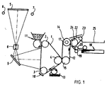
- the imaging device illustrated in Fig. 1 is provided with an endless photoconductive belt 1 which is advanced at a uniform speed by means of drive and guide rollers 2, 3 and 4 respectively.
- the image of an original placed on a window 5 is projected on to the belt 1 by means of flashlights 6 and 7, a lens 8 and a mirror 9, after the belt has been electrostatically charged by a corona device 10.
- the latent charge image forming on the belt 1 after the flash exposure is developed with toner powder by means of a magnetic brush device 11 to give a toner image that is then brought into contact under pressure with an endless intermediate medium belt 12 in a first transfer zone, said belt 12 being provided with a top layer according to the invention.
- the construction of the intermediate medium is further in accordance with EP-A 0 581 365, which by reference thereto is completely included in this application. In these conditions, the toner image is transferred by adhesion forces from the belt 1 to the belt 12.
- any remaining image residues are removed from belt 1 by means of a cleaning device 13, whereafter the photoconductive belt 1 is ready for fresh use.
- the intermediate medium belt 12 is trained over drive and guide rollers 14 and 15, the said belt being heated to a temperature above the softening temperature of the toner powder, for example by means of an infrared radiator 17 disposed inside roller 14. While belt 12 is advanced with the toner image thereon, the toner image becomes tacky as a result of the heating. In a second transfer zone, the tacky toner image is then transferred, under the influence of pressure, by means of a pressure member in the form of a belt 22 trained over rollers 23 and 24, and at the same time fixed, on a sheet of receiving material fed from reservoir 18 via rollers 19 and 20.
- the sheet of receiving material Before being introduced into the second transfer zone, the sheet of receiving material can be preheated in manner known per so in order thus to obtain better image transfer and fixing. Preheating can be effected by means known for this specific purpose.
- the heating device can consist of a heated fiat plate, possibly covered with a thin layer of adhesive material, over which the sheet of receiving material is transported in the best possible contact. Contact with the heated plate can be effected by electrostatic attraction. Suitable embodiments for a sheet transport device with electrostatic attraction against a guide plate, which can be heated to heat the sheet, are described in German Patent Application No. 38 33 302.
- the roller 14 when use is made of a transparent or practically transparent intermediate medium belt, the latter can be heated from the inside outwards by means of a radiant heater, the radiant heater being disposed just before the second transfer zone, so that any toner image present on the belt is heated practically directly and very efficiently.
- Fig. 2 is a cross-section of the device according to the invention wherein 1 denotes the imaging medium and the intermediate medium consists of a first transfer medium 30 and a second transfer medium 40.
- the transfer media are constructed in the form of metal rolls provided with elastic top layers.
- a toner image applied to the imaging medium 1 is transferred, in the first transfer zone 35, to the first transfer medium 30.
- the toner image is then transferred to the second transfer medium 40 in the transfer zone 45.
- the toner image is then transported to the second transfer zone 55, where the toner image is transferred to a receiving material fed through the nip between the second transfer medium 40 and the pressure member 50.
- the direction of transport of the toner image is denoted by arrows in the Figure.
- the two transfer media 30 and 40 can be provided with the top layer according to the invention. It is also possible to provide one of the two transfer media with the top layer according to the invention. Thus transfer medium 40 can be provided with the top layer according to the invention while transfer medium 30 is provided with a conventional silicone rubber containing top layer.
- PFPE-oil used is a PFPE-oil of formula 1 wherein PFPE has the above-mentioned meaning and n is approximately 11, m approximately 11 and m/n approximately 1, commercially available from Ausimont S.p.A. under the trade name Fluorol-ink D.
- Example 2 Synthesis of the homopolymer of 1-PFPE-aniline, doping of the homopolymer with a PFPE carboxylic acid and curing of a mixture of the doped homopolymer and an acrylate PFPE-oil.
- the conductivity measurements can be carried out in a polycarbonate cell 1 as shown in Fig. 3, a mixture of the intrinsically conductive polymer and an acrylate-PFPE-oil being cured in the space 2 between two metal electrodes 3 and 4 with UV radiation to give a PFPE-rubber.
- a voltage was then applied across the electrodes 3 and 4 and the current measured.
- the ohmic relationship between the voltage and current was determined at different concentrations of intrinsically conductive polymer in the PFPE-rubber and plotted in a voltage/current curve.
- the specific resistance of the PFPE-rubber was then determined from the directional coefficient of the voltage/current curve.
- the conductivity measurements can be carried out with a turntable experiment.
- a sample of the PFPE-rubber 2 with specific dimensions is placed on a fast rotating conductive circular turntable 1 shown in Fig. 4.
- the turntable is then charged by means of a corona charger 3, the residual voltage being measured by means of an ASV probe 4 against time.
- FIG. 5 A voltage/current curve obtained with the measuring cell in Fig. 3 is illustrated in Fig. 5 for the PFPE-rubber prepared in Experiment 3 of Example 2.
- the specific resistance of the PFPE-rubber decreases with increasing concentration of the intrinsically conductive polymer in the PFPE-rubber.
- the specific resistance was determined at concentrations of the polymer in the PFPE-rubber in the range from 10 to 20 mol%. At a 20 mol% concentration the conductivity of the PFPE-rubber is at its maximum. The conductivity measurements are reproducible.
- Example 4 PFPE-rubber with PFPE-doped copolymers of 1-PFPE-aniline or 1-acrylate-PFPE-aniline and aniline
- a conductivity of the PFPE-rubber was measured as 10 -7 S/cm with the PFPE-doped copolymer of 1-PFPE-aniline and aniline (with a polyaniline impurity of less than 0.5 mol% therein).
- the conductivity of the PFPE-rubbers with the PFPE-doped copolymer of 1-acrylate-PFPE-aniline and aniline is accurately adjustable and stable.
- the top layers containing such rubbers are antistatic.
- these rubbers can be obtained with both thermal and UV curing.
- a hexafluoro-isopropanol solution was made of polyaniline Emeraldine and MF300 in a round bottom flask. This solution was stirred overnight, whereafter the hexafluoroisopropanol was distilled off. After this, a residue remained in the flask and was filtered with a filter having a pore size of 0.5 mm. The residue was MF300-doped polyaniline containing less than 50 mol% ionogenically fixed MF300.
- the MF300-doped polyaniline was then mixed with an acrylate-PFPE oil.
- the resulting mixture was cured with UV radiation giving a PFPE-rubber.
- Aniline was mixed into an acrylate-PFPE-oil and then this mixture was cured with UV radiation or thermally, with the formation of a PFPE-rubber film.
- the aniline present in the PFPE-rubber was then oxidatively polymerised to polyaniline and doped by immersing the PFPE-rubber in an acidic oxidator solution with MF300. After some hours there was still no change of colour. After 2 days the film acquired a very dark colour. In addition, the film felt less elastic than the PFPE-rubber before polymerisation. This is due to the fact that the hydrochloric acid of the oxidator solution attacks the PFPE-rubber.
- the resulting PFPE-rubber has a high conductivity because the MF300-doped polyaniline is distributed very homogeneously therein.
- the disadvantage of this process is that the results are not very reproducible and that the ability to up-scale is low.
Landscapes
- Chemical & Material Sciences (AREA)
- Chemical Kinetics & Catalysis (AREA)
- Health & Medical Sciences (AREA)
- Medicinal Chemistry (AREA)
- Polymers & Plastics (AREA)
- Organic Chemistry (AREA)
- Physics & Mathematics (AREA)
- General Physics & Mathematics (AREA)
- Spectroscopy & Molecular Physics (AREA)
- General Chemical & Material Sciences (AREA)
- Macromolecular Compounds Obtained By Forming Nitrogen-Containing Linkages In General (AREA)
- Electrostatic Charge, Transfer And Separation In Electrography (AREA)
- Compositions Of Macromolecular Compounds (AREA)
- Macromonomer-Based Addition Polymer (AREA)
Abstract
Description
- This invention relates to an intermediate medium with a rubber top layer which contains conductive material for use as a temporary image support in an imaging device, an imaging device which comprises an intermediate medium of this kind as a temporary image support, and combinable rubber components for forming the rubber top layer of an intermediate medium according to the invention.
- Imaging techniques in which an image is formed on a temporary image support with a rubber top layer, and said image is transferred under pressure, possibly combined with a supply of heat, to a final receiving material, are known in various forms. In one very well known embodiment, a toner powder image is formed on a re-usable imaging element, such as a photoconductive element, a magnetic imaging element or an electrostatic imaging element containing a dielectric image receiving layer, and said toner powder image is transferred under pressure to an intermediate medium as specified above. The toner powder image is heated on the intermediate medium to make the toner powder tacky, whereafter in a second pressure transfer zone the tacky image is transferred and at the same time fixed on a final receiving support. The latter is heated if necessary before being introduced into the pressure transfer zone. After the image transfer in the second pressure transfer zone an additional fixing step can take place it necessary to provide optimal fixing of the image on the final image receiving support. Also, in addition to or instead of the additional fixing step, other finishing operations can take place, for example a gloss treatment. After-treatments of this kind are carried out particularly in the case of (multi-)colour images.
Other imaging processes in which intermediate media with a rubber top layer can be used are processes in which liquid ink or melted ink (hot melt ink) directly form an image on the top layer by means of an ink jet print head and said image is then transferred to the final receiving material.
The rubber top layer of the intermediate medium must have good mechanical and chemical permanency and should particularly be insensitive to the (low-melting) substances (waxes, plasticisers, etc) released from the receiving materials, particularly receiving papers. The rubber must also have a certain electric conductivity to obviate electrostatic charges. Conventional rubbers for forming the top layer are silicone rubbers and perfluoropolyether rubbers (PFPE-rubbers). - NL-A 1 001 471 proposes an intermediate medium wherein the rubber is a perfluoropolyether (PFPE) rubber. The top layer containing the PFPE-rubber described therein gives high resistance to the transfer of low-melting impurities. A process for the preparation of a PFPE-rubber by curing a lengthened-chain bifunctional PFPE-oil is described. In one embodiment, furnace black is added as a filler and conductive material to the PFPE-oil, whereafter thermal curing is carried out. In addition, a process is described for the preparation of the lengthened-chain PFPE-oils used as starting material, in which process a PFPE-oil having a weight-averaged molecular weight (Mw) in the range from 1500 to 3000 g/mol is reacted with a lengthened-chain agent selected from the group of di-acid chlorides and di-isocyanates.
- One disadvantage of the embodiment of NL-A 1 001 471, in which furnace black is contained in the PFPE-rubber-containing top layer, is that the conductivity of the PFPE-rubber cannot be adjusted within a required bandwidth and the PFPE-rubber is therefore not anti-static. Another disadvantage is that the conductivity with furnace black in the antistatic PFPE-rubber is not stable. Deformation of the PFPE-rubber in fact causes the conductive furnace black paths to be broken. Yet another disadvantage is the difficulty of curing with UV radiation a PFPE-oil which furnace black has been mixed.
- In addition, the prior art makes a number of proposals according to which, in addition to furnace black, other conductive materials such as intrinsically conductive polymers, can be included in the top layer.
- For example, US-A 5 629 094 relates to a transfer material support consisting of a substrate and a top layer. The substrate preferably consists of a resin such as a polyester, polycarbonate, polyvinylidene fluoride, Teflon, polyurethane or polyacetate. The top layer contains a polyester resin, a hardened resin and a silicone polymer. This top layer can also contain polycarbonate, polyamide, polyacrylate, polyoxymethylene, polyphenylene oxide, polyphenylene sulphide, polyethylene, polypropylene, polystyrene, a copolymer of ethylene and propylene, a copolymer of styrene and butadiene, and so on. In addition, the top layer or the substrate may contain conductive materials such as metal powder, metal oxides, gas black, graphite, carbon fibres, organic or inorganic electrolytes and intrinsically conductive polymers such as polypyrrole or polyaniline.
- US-A 5 534 581 describes a transfer material support consisting of a copolycarbonate resin and conductive particles. The conductive particles comprise furnace black, metal oxides or intrinsically conductive polymers, such as polyaniline, polythiophene and polyacetylene. The conductive particles are dispersible in high concentration in the copolycarbonate resin.
- US-A 5 430 073 relates to a process for the preparation of intrinsically conductive polymers comprising in situ activation of precursor monomers whereby activated monomers are obtained which polymerise in the presence of a catalyst. Polymerisation without activation of the precursor monomers is prevented. The intrinsically conductive polymers can, for example, be formed after mixing the precursor monomers in a polymer matrix. The intrinsically conductive polymers which are prepared with this process comprise polypyrrole, polythiophene and polyfurane which may or may not be substituted and mixtures of two or more of these polymers.
- The object of the invention is to include an intrinsically conductive polymer as conductive material in a PFPE or silicone rubber, instead of furnace black, to ensure that a rubber is formed which is antistatic. Intrinsically conductive polymers, however, are insoluble in the rubber oil (PFPE or silicone oil) used as starting material.
- The present invention provides an intrinsically conductive polymer so modified that it can be combined with the rubber oil.
- Accordingly the invention relates to an intermediate medium for use as a temporary image support in an imaging device, as described in the preamble, characterised in that the conductive material is an intrinsically conductive polymer so modified that it can be combined with the rubber oil.
- PFPE-rubber or silicone rubbers can be used as the rubber. The preferred PFPE-rubber is as described inter alia in NL-
A 1 001 471. - Conventional polymers, inter alia as described in US-A 5 629 094, US-A 5 534 581 and US-A 5 430 073, can be used as intrinsically conductive polymer. Examples are polyaniline, polypyrrole, polythiophene. A very suitable polymer is a modified polyaniline. The conductive polymer can be modified in various ways.
- For example, a conductive polymer can be used that is doped with a PFPE-carboxylic acid. The PFPE-carboxylic acid preferably has the formula:
- Preferably, the polyaniline used is modified by substituting it on the aromatic ring with a PFPE-chain. Particularly preferred is the use of a modified polyaniline which is a copolymer formed by polymerisation of aniline and aniline substituted on the aromatic ring with a PFPE-chain. The PFPE-chain is preferably a linear [(OCF2)m(OCF2C-F2)n] chain where m and n are in the range from 9 to 13. One advantage of such modified polyanilines is that very good miscibility in a PFPE-oil used as starting material is obtained.
- The homopolymers or copolymers of aniline substituted with a PFPE-chain can be further modified by doping them with a PFPE-carboxylic acid as described hereinbefore. An advantage of such a modified polyaniline is that when it is mixed in a PFPE-oil used as starting material high conductivity is transferred to a PFPE-rubber.
- The PFPE-chains of the homopolymers or copolymers of aniline substituted with a PFPE-chain can be provided with an acrylate group. An advantage of such a modified polyaniline is that when it is combined in a PFPE-rubber via the acrylate group accurately adjustable and stable conductivity of the PFPE-rubber is obtained together with a wide choice in respect of the curing methods.
- The process for the preparation of the modified polyaniline according to the present invention comprises the following reaction steps.
-
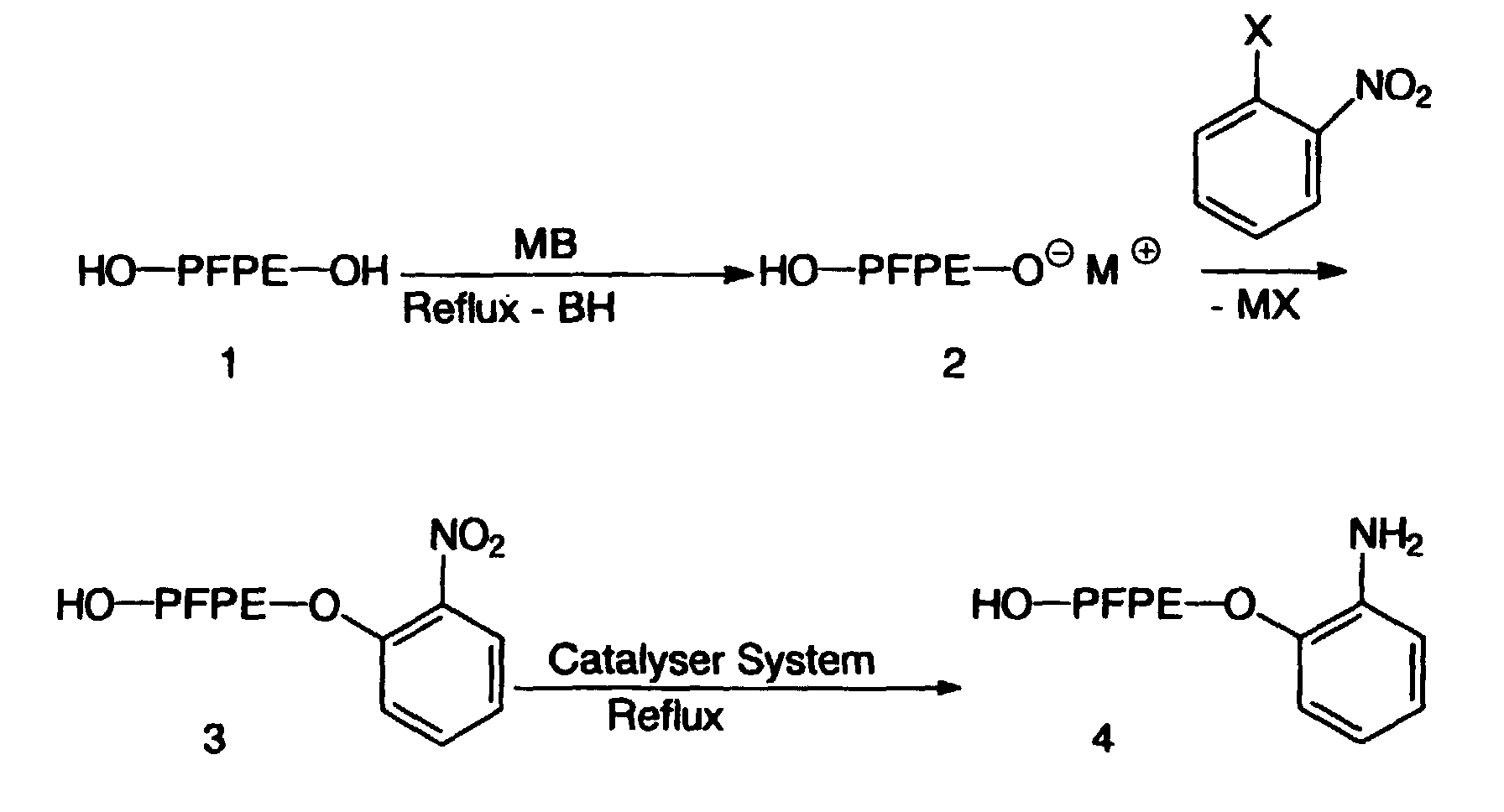
- In this reaction step, a fluoridised oil of
formula 1 is converted with 0.5 equivalent of a base MB into the salt thereof having theformula 2. - The fluoridised oil used is preferably a fluondised oil in which in
formula 1 PFPE denoteswhere OCF2 and OCF2CF2 groups are randomly distributed. The base used is preferably an alkali metal oxide, for example potassium tert.butoxide, which yields the alkali metal salt of
formula 2. There is no need to use a solvent to perform the reaction, but if required it can be used to bring the viscosity of the reaction mixture to a preferred level, If a solvent is used, it is preferably a non-reactive fluoridised solvent. - The salt of
formula 2 is then reacted with nitrobenzene which on the ortho or meta position is substituted with a halogen atom X, giving a compound offormula 3. The halogen atom X is preferably a fluorine atom. - The compound of
formula 3 is then reduced to a compound offormula 4, with the use of a catalyst system. A preferred catalyst system consists of Fe(II-I)Cl3, carbon and hydrazine hydrate. The solvent used is preferably a non-reactive fluoridised solvent. - The synthesis of compounds of
formula 4 is described in T. Hirashime, O. Manare, Chemistry Letters, 1975, pages 259-260. - In this reaction step, the
formula 4 compound is polymerised to aformula 5 homopolymer by the use of a catalyst system:where PFPE has the above-mentioned meaning.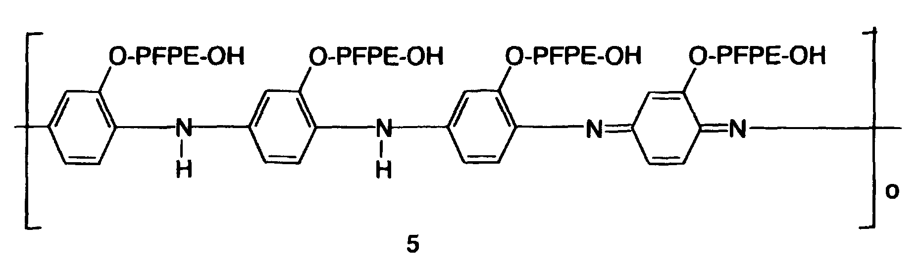
- The catalyst system used is preferably a system consisting of 30% hydrochloric acid and ammonium persulphate. The solvent used is preferably a non-reactive fluoridised solvent.
- The value of the length of the
formula 5 homopolymer shown by o depends greatly on the polymerisation conditions used. - The copolymer of PFPE-modified aniline and non-modified aniline can be prepared by adding aniline to the
formula 4 compound before polymerisation. The resulting copolymer is a random block copolymer of blocks of polyaniline and PFPE-modified polyaniline. Aniline is not soluble in theformula 4 compound nor in a fluoridised solvent. Consequently, the copolymerisation of aniline and theformula 4 compound proceeds via a heterogeneous mechanism, i.e. copolymerisation takes place at the interface of the separate phases. In addition, quantum mechanics calculations have shown that aniline is more reactive in the polymerisation reaction than theformula 4 compound. Consequently, a polyaniline fraction, a fraction of theformula 5 homopolymer and a copolymer fraction can be formed during the copolymerisation reaction. - The copolymerisation process can be controlled by varying the concentration and rates of feed of the monomers. The interface between the fluoridised solvent phase and the aqueous phase can be enlarged by stirring. In addition, the length of the various blocks in the copolymer can be controlled by varying the rate of polymerisation in the separate phases.
- The PFPE-modified homopolymer or copolymer has a higher miscibility in an acrylate-PFPE-oil than a non-modified polyaniline.
- In this reaction step, the
formula 5 homopolymer is doped with a dopant having the formulawhere PFPE has the above-mentioned meaning. The dopant used is an agent which protonises the basic nitrogen atom of the homopolymer, the anion of the dopant forming an ionogenic bond with the protonised nitrogen atom. The anion produces an electron deficiency in the polymer chain, which provides electron conductivity in the chain. The maximum and optimal percentage of protonised nitrogen atoms is 50 mol%.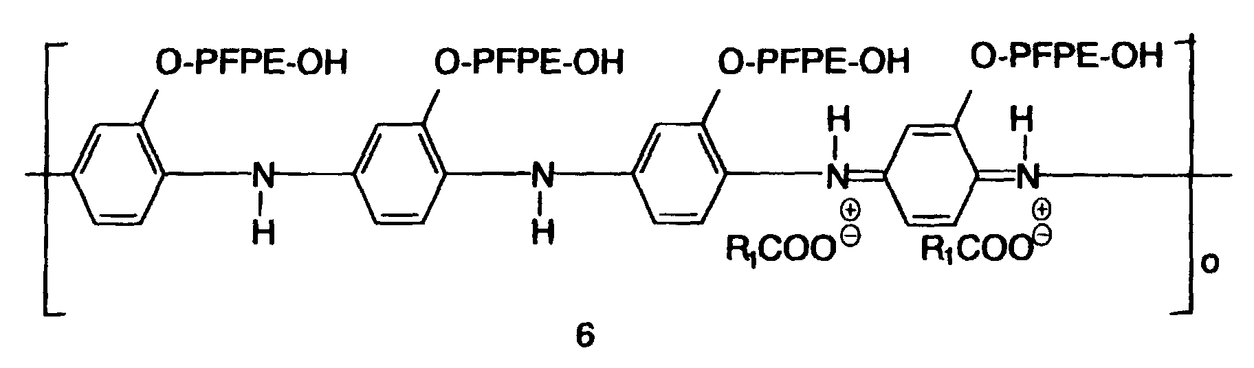
- The dopant used is preferably a fluoridised carboxylic acid. It is more preferable to use a fluoridised carboxylic acid in the formula of which R1 denotes
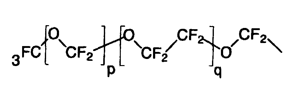
- Doping of the copolymer from the second reaction step can be carried out in the same way as for the homopolymer.
- Doping is needed to obtain conductivity and an increased miscibility in a PFPE oil of the homopolymer or copolymer. It is assumed that a doped homopolymer or copolymer consists of blocks which conduct satisfactorily, i.e. those in which the nitrogen atoms are protonised, and blocks of less or no conductivity.
- In this possible reaction step the PFPE chain of the formula 6 homopolymer from the third reaction step is terminated with an acrylate group by means of an alkenoyl chloride with hydrochloric acid being split off, giving a homopolymer of formula 7where R1 has the above-mentioned meaning and R2 denotes
 where PFPE has the above-mentioned meaning. Preferably, the alkenoyl halide used is propenoyl chloride.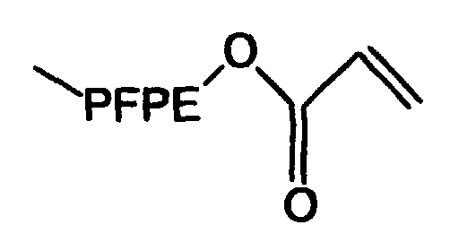
- Termination with an acrylate group of the copolymer from the third reaction step can be carried out in the same way as for the homopolymer.
- By termination with an acrylate group the intrinsic conductivity of the homopolymer or copolymer is not changed. Termination with an acrylate group, however, is needed if it is desirable to combine the homopolymer or copolymer with the PFPE-rubber. By such a combination the homopolymer or copolymer becomes a fixed part of the rubber and an interpenetrating network is formed. This can be desirable, for example, if the R1 and R2 groups form a sol fraction which has adverse effects on the visco-elastic properties of the PFPE-rubber.
- It is possible to carry out the termination with an acrylate group in an earlier stage, for example directly after the polymerisation in
reaction step 2. It is also possible to perform the termination in a later stage, for example after the mixing of the homopolymer or copolymer into an acrylate-PFPE oil. - The resulting homopolymer or copolymer is then mixed into a PFPE-oil terminated with acrylate groups (hereinafter referred to as "acrylate-PFPE-oil") having the formula
- The mixture of the homopolymer or copolymer and the acrylate-PFPE-oil is then cured. UV-radiation or thermal curing can be applied. Curing is performed in accordance with NL-
A 1 001 471, the content of which by this reference is included completely in this application. It will be clear that instead of acrylate group termination it is possible to introduce any other reactive group provided said group is sufficiently reactive, under the reaction conditions selected, with respect to reactive groups already present or incorporated in the rubber-oil. Examples of other reactive groups suitable for termination are triethoxy, epoxy, hydroxyl, cyanate and isocyanate groups. - In yet another embodiment of the invention, the intrinsically conductive polymer of the top layer is a PFPE-carboxylic acid doped, non-modified polyaniline. A polyaniline of this kind is obtained in the manner described above for the third reaction step subject to the condition of polyaniline is used as a polymer.
- The PFPE-carboxylic acid doped polyaniline can also be prepared in the following manner. Firstly, aniline is mixed in an acrylate-PFPE-oil and then this mixture is cured as described above, yielding a PFPE-rubber. The aniline present in the PFPE-rubber is then polymerised oxidatively to form polyaniline and doped by immersing the rubber in an acidic oxidator solution with PFPE-carboxylic acid.
- The invention will now be explained in detail with reference to the drawings and a number of examples without limiting force. In the drawings:
- Fig. 1 is a diagrammatic cross-section of one embodiment of the apparatus according to the invention.
- Fig. 2 is a diagrammatic cross-section of another embodiment of the apparatus according to the invention.
- Fig. 3 shows an apparatus for performing conductivity measurements on the PFPE-rubber according to the invention.
- Fig. 4 shows another apparatus for performing conductivity measurements on the PFPE-rubber according to the invention.
- Fig. 5 is a voltage/current curve as obtained with the conductivity measurement on a PFPE-rubber according to the invention.
-
- The construction of the apparatus of the present invention is the construction according to NL-
A 1 001 471, the content of which, by this reference, is completely included in this patent application. - The imaging device illustrated in Fig. 1 is provided with an endless
photoconductive belt 1 which is advanced at a uniform speed by means of drive and guiderollers window 5 is projected on to thebelt 1 by means of flashlights 6 and 7, alens 8 and amirror 9, after the belt has been electrostatically charged by acorona device 10. The latent charge image forming on thebelt 1 after the flash exposure is developed with toner powder by means of amagnetic brush device 11 to give a toner image that is then brought into contact under pressure with an endless intermediatemedium belt 12 in a first transfer zone, saidbelt 12 being provided with a top layer according to the invention. The construction of the intermediate medium is further in accordance with EP-A 0 581 365, which by reference thereto is completely included in this application. In these conditions, the toner image is transferred by adhesion forces from thebelt 1 to thebelt 12. - After this image transfer, any remaining image residues are removed from
belt 1 by means of acleaning device 13, whereafter thephotoconductive belt 1 is ready for fresh use. - The intermediate
medium belt 12 is trained over drive and guiderollers infrared radiator 17 disposed insideroller 14. Whilebelt 12 is advanced with the toner image thereon, the toner image becomes tacky as a result of the heating. In a second transfer zone, the tacky toner image is then transferred, under the influence of pressure, by means of a pressure member in the form of abelt 22 trained overrollers reservoir 18 viarollers - Finally, the copy obtained in this way is deposited in
delivery tray 25 bybelt 22, which is trained overrollers - Before being introduced into the second transfer zone, the sheet of receiving material can be preheated in manner known per so in order thus to obtain better image transfer and fixing. Preheating can be effected by means known for this specific purpose. For example, the heating device can consist of a heated fiat plate, possibly covered with a thin layer of adhesive material, over which the sheet of receiving material is transported in the best possible contact. Contact with the heated plate can be effected by electrostatic attraction. Suitable embodiments for a sheet transport device with electrostatic attraction against a guide plate, which can be heated to heat the sheet, are described in German Patent Application No. 38 33 302.
- Instead of heating the
roller 14, when use is made of a transparent or practically transparent intermediate medium belt, the latter can be heated from the inside outwards by means of a radiant heater, the radiant heater being disposed just before the second transfer zone, so that any toner image present on the belt is heated practically directly and very efficiently. - Fig. 2 is a cross-section of the device according to the invention wherein 1 denotes the imaging medium and the intermediate medium consists of a
first transfer medium 30 and asecond transfer medium 40. The transfer media are constructed in the form of metal rolls provided with elastic top layers. A toner image applied to theimaging medium 1 is transferred, in thefirst transfer zone 35, to thefirst transfer medium 30. The toner image is then transferred to thesecond transfer medium 40 in thetransfer zone 45. The toner image is then transported to thesecond transfer zone 55, where the toner image is transferred to a receiving material fed through the nip between thesecond transfer medium 40 and thepressure member 50. The direction of transport of the toner image is denoted by arrows in the Figure. - The two
transfer media transfer medium 30 is provided with a conventional silicone rubber containing top layer. - 10.0 g (14.0 mmol) of a PFPE-oil of
formula 1 commercially available from Ausimont S.p.A., Milan, Italy, under the trade name MF402 (molecular weight 1400 mmol/kg), is dissolved in 10 ml of a fluoridised solvent commercially available again from Ausimont, S.p.A., under the trade name Fomblin PFS1 (hereinafter referred to as "PFS-1"-). The mixture obtained in this way is cooled to 0°C. 1.3 g (11.6 mmol) of potassium tert.butoxide is then added in four batches during stirring. After the addition, the reaction mixture is then stirred for 1 hour at 0°C and then for 4 hours at room temperature. 1.6 g (11 mmol) of 1-fluoronitro-benzene is then added to the reaction mixture, salt formation being observed. After the reaction mixture has been left overnight, it is poured into water and the various layers are separated. Kugelrohr distillation (at 120°C, 2 mbar) yields 1-PFPE-nitro-benzene (8.3 g (10 mmol), yield 85%). - 1H-NMR[200 MHz, d-acetonitrile] (ppm): σ 7.82 (1H, ArH(6)-), 7.60 (1H, ArH(4)), 7.20 (2H, ArH(3.5)), 4.63 (2H, -CH2-).
-
- Another example of a PFPE-oil used is a PFPE-oil of
formula 1 wherein PFPE has the above-mentioned meaning and n is approximately 11, m approximately 11 and m/n approximately 1, commercially available from Ausimont S.p.A. under the trade name Fluorol-ink D. - 8.3 g (10 mmol) of the 1-PFPE-nitrobenzene obtained in the previous step is dissolved in 5 ml PFS1, whereafter 5 mg Fe(III)Cl3 and 0.3 g active carbon were added to the solution thus obtained. The mixture thus obtained was then heated to reflux. After 15 minutes reflux 0.8 g (15 mmol) of hydrazine hydrate was added during a period of 1 hour. After the addition, the reaction mixture was stirred with reflux overnight. The reaction mixture was then filtered to remove the active carbon. Kugelrohr distillation (at 110°C, 1 mbar) yielded 1-PFPE aniline (7 g (9 mmol), yield 90%).
- 1H-NMR [200 MHz, d-acetonitrile] (ppm): σ 6.83-6.62 (m, 4H, ArH), 4.46 (t, 2H, - CH2-), 4.06 (wide, 2H, -NH2-).
- ATR-IR (cm-1): 1620 (-NH2; deformation), 1591 and 1508 (C=C; valency aromate), 1460 (-CH2-; deformation), 1300-900 (C-F; PFPE), 745 (aromate; 1,2-substitution).
-
- 0.894 g 1-PFPE-aniline as obtained in Example 1, 1 ml PFS1, 2.0 ml of a PFPE carboxylic acid commercially available from Ausimont S.p.A. under the trade name Galden MF300 (hereinafter referred to as "MF300") and the formula R1COOH where R1 has the above-mentioned meaning wherein p is approximately 7, q approximately 7 and p/q approximately 1, and 0.14 g ammonium persulphate were mixed. This mixture was stirred for 2 hours at 0°C. 1 ml water and 1 ml 0.15 M hydrochloric acid were then added to the mixture. After stirring overnight the reaction mixture has a purple colour. After 14 hours' stirring the purple reaction mixture was transferred to a separating funnel to separate the PFS1 phase and the aqueous phase. The dark purple PFS1 phase was transferred to a round bottom flask and the PFS1 was then evaporated, leaving a dark purple liquid residue in the round bottom flask. The NMR and IR values of this residue indicate the MF300 doped homopolymer of 1-PFPE-aniline.
- 1H-NMR [200 MHz, d-acetonitrile] (ppm): σ 6.88-6.70 (m, 4H, ArH), 4.48 (t, 2H, - CH2-).
- ATR-IR (cm-1): 1660 (Ar=N-Ar; elongation), 1591 and 1508 (C=C; valency aromate), 1460 (-CH2-; deformation); 1300-900 (C-F; PFPE), 745 (aromate; 1,2-substitution).
-
- 0.09450 g of the resulting MF300 doped homopolymer of 1-PFPE-aniline was dissolved in 1.2 g acrylate-PFPE-oil (4.4% by weight 1-PFPE-polyaniline and 1.0% by weight polyaniline). The solution was deaerated and cured in a nitrogen atmosphere under an UV lamp, resulting in the formation of a clear brown PFPE-rubber film.
- 0.14 g of ammonium persulphate was dissolved in 1.4 ml 0.15 M hydrochloric acid and 1.0 g 1-PFPE-aniline as obtained in Example 1 was dissolved in 1.4 ml of hexafluoro-isopropanol. The ammonium persulphate solution was then slowly added by means of an injection nozzle to the 1-PFPE-aniline solution at 0°C. Polymerisation progresses fairly rapidly for after addition of a few drops of APS solution the solution already turns pink. After 2 hours' stirring, the reaction mixture has a purple colour. After 2 to 3 hours' stirring the purple reaction mixture was transferred to a separating funnel to separate the hexafluoro-isopropanol phase and the aqueous phase. The dark purple hexafluoro-isopropanol phase was transferred to a round bottom flask and the hexafluoro-isopropanol was then evaporated, leaving a dark red/brown residue in the flask. The NMR and IR values of this residue indicate the homopolymer of 1-PFPE-aniline.
- 1H-NMR [200 MHz, d-acetonitrile] (ppm): σ 7.29-7.03 (m, 4H, ArH), 4.59 (t, 2H, - CH2-).
- ATR-IR (cm-1): 1660 (-NH-; deformation), 1591 and 1508 (C=C; valency aromate), 1460 (-CH2-; deformation); 1300-900 (C-F; PFPE), 745 (aromate; 1,2-substitution).
-
- 2.66 g ammonium persulphate was dissolved in 26 ml 0.15 M hydrochloric acid and 10.45 g 1-PFPE-aniline as obtained in Example 1 was dissolved in 30 ml of a fluoridised solvent commercially available from the 3M Company, USA, under the trade name Fluorinert FC75 (hereinafter referred to as "Fluorinert"). The Fluorinert solution was cooled to a temperature in the range of -10 to -1°C by means of an acetone/ice bath. The ammonium persulphate solution was then added slowly in a period of 2 hours with stirring. After the addition, the reaction mixture was stirred for another 2 hours at said temperature and then for 16 hours at room temperature, resulting in a viscous dark brown/purple solution being formed. Polymerisation progresses approximately at the same rate as in
Experiment 2, hexafluoro-isopropanol being used as solvent instead of Fluorinert After the addition of water, the solution was transferred to a separating funnel to separate the Fluorinert phase and the aqueous phase. The Fluorinert phase was transferred to a round bottom flask and then the Fluorinert was evaporated on a film evaporator, a very viscous dark brown residue remaining in the flask. The IR values of this residue indicate the homopolymer of 1-PFPE-aniline. - ATR-IR (cm-1): 3750-2800 (-OH; H2O), 1660 (Ar=N-Ar; elongation), 1591 and 1508 (C=C; valency aromate), 1460 (-CH2-; deformation); 1300-900 (C-F; PFPE), 745 (aromate; 1,2-substitution).
-
- 1.32 g (1.64 mmol monomer units) of the above homopolymer of 1-PFPE-aniline was dissolved in 6.28 g hexafluoro-isopropanol and then 2.02 g (2.4 mmol) MF300 were added to the resulting solution. A large quantity of the hexafluoro-isopropanol in the dark red/brown solution was then evaporated on a film evaporator, a residue remaining. This residue was dissolved in an acrylate-PFPE-oil. The resulting solution was deaerated and cured in a nitrogen atmosphere under an UV lamp. This resulted in a PFPE-rubber forming, on which conductivity measurements were carried out (see Example 3).
- The conductivity measurements can be carried out in a
polycarbonate cell 1 as shown in Fig. 3, a mixture of the intrinsically conductive polymer and an acrylate-PFPE-oil being cured in thespace 2 between twometal electrodes electrodes - In addition, the conductivity measurements can be carried out with a turntable experiment. A sample of the PFPE-
rubber 2 with specific dimensions is placed on a fast rotating conductivecircular turntable 1 shown in Fig. 4. The turntable is then charged by means of acorona charger 3, the residual voltage being measured by means of anASV probe 4 against time. - A voltage/current curve obtained with the measuring cell in Fig. 3 is illustrated in Fig. 5 for the PFPE-rubber prepared in
Experiment 3 of Example 2. - It will be apparent from Fig. 5 that the specific resistance of the PFPE-rubber decreases with increasing concentration of the intrinsically conductive polymer in the PFPE-rubber. The specific resistance was determined at concentrations of the polymer in the PFPE-rubber in the range from 10 to 20 mol%. At a 20 mol% concentration the conductivity of the PFPE-rubber is at its maximum. The conductivity measurements are reproducible.
- A conductivity of the PFPE-rubber was measured as
10-7 S/cm with the PFPE-doped copolymer of 1-PFPE-aniline and aniline (with a polyaniline impurity of less than 0.5 mol% therein). - The conductivity of the PFPE-rubbers with the PFPE-doped copolymer of 1-acrylate-PFPE-aniline and aniline is accurately adjustable and stable. The top layers containing such rubbers are antistatic. In addition, these rubbers can be obtained with both thermal and UV curing.
- 0.02366 g (0.13 mmol monomer units) polyaniline Emeraldine, and 0.1 ml (approximately 0.1 mmol) MF300 were dissolved in PFS1. After 16 hours' stirring a light green solution formed which contained MF300-doped polyaniline.
- A hexafluoro-isopropanol solution was made of polyaniline Emeraldine and MF300 in a round bottom flask. This solution was stirred overnight, whereafter the hexafluoroisopropanol was distilled off. After this, a residue remained in the flask and was filtered with a filter having a pore size of 0.5 mm. The residue was MF300-doped polyaniline containing less than 50 mol% ionogenically fixed MF300.
- The MF300-doped polyaniline was then mixed with an acrylate-PFPE oil. The resulting mixture was cured with UV radiation giving a PFPE-rubber.
- Conductivity measurements on the PFPE-rubber obtained in this way show that good results were only obtained if low concentrations of polyaniline were added. At concentrations higher than 1 mol% the miscibility is not good and also curing with UV radiation is impossible.
- Aniline was mixed into an acrylate-PFPE-oil and then this mixture was cured with UV radiation or thermally, with the formation of a PFPE-rubber film. The aniline present in the PFPE-rubber was then oxidatively polymerised to polyaniline and doped by immersing the PFPE-rubber in an acidic oxidator solution with MF300. After some hours there was still no change of colour. After 2 days the film acquired a very dark colour. In addition, the film felt less elastic than the PFPE-rubber before polymerisation. This is due to the fact that the hydrochloric acid of the oxidator solution attacks the PFPE-rubber.
- The resulting PFPE-rubber has a high conductivity because the MF300-doped polyaniline is distributed very homogeneously therein. The disadvantage of this process is that the results are not very reproducible and that the ability to up-scale is low.
- Similar modifications to those described above in respect of polyaniline can be carried out on other conductive polymers, such as polypyrroles and polythiophenes. Instead of or in addition to PFPE-rubber, it is possible, as indicated previously, to use silicone rubbers.
Claims (17)
- An intermediate medium for use as a temporary image support in an imaging device, the said intermediate medium being provided with a rubber top layer which contains conductive material and which is formed by polymerising rubber oil in the presence of the conductive material, characterised in that the conductive material comprises an intrinsically conductive polymer so modified that it can be combined with the rubber oil.
- An intermediate medium according to claim 1, characterised in that the rubber is a perfluoropolyether rubber.
- An intermediate medium according to claim 2, characterised in that the perfluoropolyether rubber has linear [(OCF2)m(-OCF2CF2)n] chains where m and n are between 9 and 13.
- An intermediate medium according to any one of the preceding claims, characterised in that the modified intrinsically conductive polymer is modified polyaniline.
- An intermediate medium according to claim 4, characterised in that the modified polyaniline consists of polyaniline doped with a perfluoropolyether carboxylic acid.
- An intermediate medium according to claim 5, characterised in that the perfluoropolyether carboxylic acid has the formula
- An intermediate medium according to claim 4, characterised in that the modified polyaniline consists of polyaniline which on the aromatic ring is substituted with a perfluoropolyether chain.
- An intermediate medium according to claim 7, characterised in that the perfluoropolyether chain on the aromatic ring of the modified polyaniline is a linear (OCF2)m-(OCF2CF2)n chain where m and n are in the range from 9 to 13.
- An intermediate medium according to claim 7 or 8, characterised in that the perfluoropolyether chain on the aromatic ring of the modified polyaniline also has an acrylate group.
- An intermediate medium according to claim 4, characterised in that the modified polyaniline is a copolymer formed by polymerisation of aniline and aniline which on the aromatic ring is substituted with a perfluoropolyether chain.
- An intermediate medium according to claim 10, characterised in that the perfluoropolyether chain on the aromatic ring of the modified polyaniline is a linear (OCF2)m-(OCF2CF2)n chain where m and n are in the range from 9 to 13.
- An intermediate medium according to claim 10 or 11, characterised in that the perfluoropolyether chain on the aromatic ring of the modified polyaniline also has an acrylate group.
- An intermediate medium according to any one of claims 7 to 12, characterised in that the modified polyaniline is also doped with a perfluoropolyether carboxylic acid.
- An intermediate medium according to claim 13, characterised in that the perfluoropolyether carboxylic acid has the formula:
- An imaging device comprising, as a temporary image support, an intermediate medium with a rubber top layer which contains conductive material, characterised in that the intermediate medium is an intermediate medium according to one or more of the preceding claims 1 to 14.
- A compound for forming a rubber top layer for an intermediate medium according to one or more of the preceding claims 1 to 14 which compound contains conductive material and rubber oil which can be combined to form rubber, characterised in that the conductive material contains an intrinsically conductive polymer so modified that it can be combined wit the rubber oil.
- A compound according to claim 16, characterised in that the intrinsically conductive polymer contains a polymer according to one or more of the preceding claims 4 - 14.
Applications Claiming Priority (2)
| Application Number | Priority Date | Filing Date | Title |
|---|---|---|---|
| NL1012551A NL1012551C2 (en) | 1999-07-09 | 1999-07-09 | Intermediate medium for transferring a toner image from an imaging medium to a final receiving material. |
| NL1012551 | 1999-07-09 |
Publications (2)
| Publication Number | Publication Date |
|---|---|
| EP1067441A1 true EP1067441A1 (en) | 2001-01-10 |
| EP1067441B1 EP1067441B1 (en) | 2004-02-11 |
Family
ID=19769531
Family Applications (1)
| Application Number | Title | Priority Date | Filing Date |
|---|---|---|---|
| EP20000202202 Expired - Lifetime EP1067441B1 (en) | 1999-07-09 | 2000-06-26 | An intermediate medium for transferring a toner image from an imaging medium to a final receiving material |
Country Status (5)
| Country | Link |
|---|---|
| US (1) | US6531227B1 (en) |
| EP (1) | EP1067441B1 (en) |
| JP (1) | JP4217371B2 (en) |
| DE (1) | DE60008171T2 (en) |
| NL (1) | NL1012551C2 (en) |
Families Citing this family (6)
| Publication number | Priority date | Publication date | Assignee | Title |
|---|---|---|---|---|
| US7031647B2 (en) * | 2004-04-14 | 2006-04-18 | Xerox Corporation | Imageable seamed belts with lignin sulfonic acid doped polyaniline |
| EP1741729B1 (en) * | 2005-07-07 | 2008-03-12 | Solvay Solexis S.p.A. | Polymerization process |
| US8197937B2 (en) * | 2009-03-30 | 2012-06-12 | Xerox Corporation | Perfluoropolyether polymer grafted polyaniline containing intermediate transfer members |
| US10363453B2 (en) | 2011-02-07 | 2019-07-30 | New Balance Athletics, Inc. | Systems and methods for monitoring athletic and physiological performance |
| DE112013001907B4 (en) | 2012-04-06 | 2020-03-12 | Canon Kabushiki Kaisha | Intermediate electrophotographic member and electrophotographic device |
| US8865306B2 (en) * | 2012-05-29 | 2014-10-21 | Xerox Corporation | Intermediate transfer members containing fluorinated polyamic acids |
Citations (7)
| Publication number | Priority date | Publication date | Assignee | Title |
|---|---|---|---|---|
| JPH01267658A (en) * | 1988-04-20 | 1989-10-25 | Fuji Xerox Co Ltd | Image recorder |
| JPH04372623A (en) * | 1991-06-21 | 1992-12-25 | Tomoegawa Paper Co Ltd | Polyaniline derivative and its production |
| JPH05194733A (en) * | 1992-01-17 | 1993-08-03 | Tomoegawa Paper Co Ltd | Polyaniline derivative and its production |
| JPH05287198A (en) * | 1992-03-12 | 1993-11-02 | Tomoegawa Paper Co Ltd | Conductive composition |
| US5436708A (en) * | 1994-05-31 | 1995-07-25 | Lexmark International, Inc. | High stability color imaging by transfer roller |
| US5585903A (en) * | 1994-10-07 | 1996-12-17 | Xerox Corporation | Fluorocarbon elastomer single layer intermediate transfer member |
| EP0773482A1 (en) * | 1995-10-23 | 1997-05-14 | Océ-Nederland B.V. | Apparatus for transferring a toner image from an image-forming medium to a receiving material |
Family Cites Families (7)
| Publication number | Priority date | Publication date | Assignee | Title |
|---|---|---|---|---|
| US5430073A (en) | 1991-01-17 | 1995-07-04 | Dsm, N.V. | Process for preparing polymers and mouling compounds based thereon |
| DE69222214T2 (en) | 1991-03-28 | 1998-02-26 | Canon Kk | Transfer material-carrying member and imaging apparatus using the same |
| US5378404A (en) * | 1991-04-22 | 1995-01-03 | Alliedsignal Inc. | Process for forming dispersions or solutions of electrically conductive conjugated polymers in a polymeric or liquid phase |
| US5305627A (en) | 1992-07-27 | 1994-04-26 | Fatigue Technology, Inc. | Split sleeve cold expansion |
| US5629094A (en) | 1994-01-31 | 1997-05-13 | Canon Kabushiki Kaisha | Image transfer medium carrier member and image forming apparatus incorporating the same |
| NL1001472C2 (en) | 1995-10-23 | 1997-04-25 | Oce Nederland Bv | Bifunctional per:fluoro:polyether oil |
| US5978639A (en) * | 1997-05-02 | 1999-11-02 | Bridgestone Corporation | Intermediate transfer member and intermediate transfer device |
-
1999
- 1999-07-09 NL NL1012551A patent/NL1012551C2/en not_active IP Right Cessation
-
2000
- 2000-06-26 DE DE2000608171 patent/DE60008171T2/en not_active Expired - Lifetime
- 2000-06-26 EP EP20000202202 patent/EP1067441B1/en not_active Expired - Lifetime
- 2000-07-06 JP JP2000205544A patent/JP4217371B2/en not_active Expired - Fee Related
- 2000-07-06 US US09/612,408 patent/US6531227B1/en not_active Expired - Lifetime
Patent Citations (7)
| Publication number | Priority date | Publication date | Assignee | Title |
|---|---|---|---|---|
| JPH01267658A (en) * | 1988-04-20 | 1989-10-25 | Fuji Xerox Co Ltd | Image recorder |
| JPH04372623A (en) * | 1991-06-21 | 1992-12-25 | Tomoegawa Paper Co Ltd | Polyaniline derivative and its production |
| JPH05194733A (en) * | 1992-01-17 | 1993-08-03 | Tomoegawa Paper Co Ltd | Polyaniline derivative and its production |
| JPH05287198A (en) * | 1992-03-12 | 1993-11-02 | Tomoegawa Paper Co Ltd | Conductive composition |
| US5436708A (en) * | 1994-05-31 | 1995-07-25 | Lexmark International, Inc. | High stability color imaging by transfer roller |
| US5585903A (en) * | 1994-10-07 | 1996-12-17 | Xerox Corporation | Fluorocarbon elastomer single layer intermediate transfer member |
| EP0773482A1 (en) * | 1995-10-23 | 1997-05-14 | Océ-Nederland B.V. | Apparatus for transferring a toner image from an image-forming medium to a receiving material |
Non-Patent Citations (4)
| Title |
|---|
| DATABASE WPI Section Ch Week 199335, Derwent World Patents Index; Class A05, AN 1993-278354, XP002132340 * |
| DATABASE WPI Section Ch Week 199348, Derwent World Patents Index; Class A05, AN 1993-383249, XP002132339 * |
| PATENT ABSTRACTS OF JAPAN vol. 14, no. 27 (P - 992) 19 January 1990 (1990-01-19) * |
| PATENT ABSTRACTS OF JAPAN vol. 17, no. 247 (C - 1059) 18 May 1993 (1993-05-18) * |
Also Published As
| Publication number | Publication date |
|---|---|
| EP1067441B1 (en) | 2004-02-11 |
| NL1012551C2 (en) | 2001-01-10 |
| JP4217371B2 (en) | 2009-01-28 |
| DE60008171D1 (en) | 2004-03-18 |
| JP2001066913A (en) | 2001-03-16 |
| DE60008171T2 (en) | 2004-08-05 |
| US6531227B1 (en) | 2003-03-11 |
Similar Documents
| Publication | Publication Date | Title |
|---|---|---|
| US6107439A (en) | Cross linked conducting compositions | |
| US6397034B1 (en) | Fluorinated carbon filled polyimide intermediate transfer components | |
| JP2615267B2 (en) | Liquid toner for electrophotography | |
| US5849399A (en) | Bias transfer members with fluorinated carbon filled fluoroelastomer outer layer | |
| EP0773482B1 (en) | Apparatus for transferring a toner image from an image-forming medium to a receiving material | |
| US5156915A (en) | Moisture stable polyurethane biasable members | |
| JP3189914B2 (en) | Electrophotographic imaging member containing polyarylamine polyester | |
| EP0805170A2 (en) | Photoconductor coating | |
| EP0899615B1 (en) | Polyimide biasable components | |
| JPH0338663A (en) | Electrophotographic charging member and electrophotographic device | |
| EP1067441B1 (en) | An intermediate medium for transferring a toner image from an imaging medium to a final receiving material | |
| US5753317A (en) | Electrically conductive processes | |
| US5233008A (en) | Polymeric diols, polyurethanes and coated articles useful as toner fusing members | |
| US5795500A (en) | Electrically conductive coatings comprising fluorinated carbon filled fluoroelastomer | |
| JPH02242265A (en) | Electrophotographic sensitive body | |
| CN103959174B (en) | Alcohol-soluble hole transport materials for organic photoconductor coatings | |
| US5162485A (en) | Bisphenol based polyesters useful in photoreceptor matrices | |
| US20020086148A1 (en) | Nonbleeding fluorinated carbon and zinc oxide filled layer for bias charging member | |
| EP0665476B1 (en) | Image transfer medium carrier member and image forming apparatus incorporating the same | |
| EP2761376B1 (en) | Endless belt | |
| JP3732552B2 (en) | Electrostatic transfer member and method for controlling resistivity thereof | |
| JP4089667B2 (en) | Semiconductive member for electrophotographic equipment | |
| CN115236958A (en) | Electrophotographic belt and electrophotographic image forming apparatus | |
| EP4495699A1 (en) | Electrophotographic member, electrophotographic image forming apparatus, and electrically conductive resin composition | |
| JP2003202014A (en) | Semiconducting rubber roll |
Legal Events
| Date | Code | Title | Description |
|---|---|---|---|
| PUAI | Public reference made under article 153(3) epc to a published international application that has entered the european phase |
Free format text: ORIGINAL CODE: 0009012 |
|
| AK | Designated contracting states |
Kind code of ref document: A1 Designated state(s): DE FR GB NL |
|
| AX | Request for extension of the european patent |
Free format text: AL;LT;LV;MK;RO;SI |
|
| 17P | Request for examination filed |
Effective date: 20010710 |
|
| AKX | Designation fees paid |
Free format text: DE FR GB NL |
|
| GRAP | Despatch of communication of intention to grant a patent |
Free format text: ORIGINAL CODE: EPIDOSNIGR1 |
|
| RTI1 | Title (correction) |
Free format text: AN INTERMEDIATE MEDIUM FOR TRANSFERRING A TONER IMAGE FROM AN IMAGING MEDIUM TO A FINAL RECEIVING MATERIAL |
|
| GRAS | Grant fee paid |
Free format text: ORIGINAL CODE: EPIDOSNIGR3 |
|
| GRAA | (expected) grant |
Free format text: ORIGINAL CODE: 0009210 |
|
| AK | Designated contracting states |
Kind code of ref document: B1 Designated state(s): DE FR GB NL |
|
| REG | Reference to a national code |
Ref country code: GB Ref legal event code: FG4D |
|
| REF | Corresponds to: |
Ref document number: 60008171 Country of ref document: DE Date of ref document: 20040318 Kind code of ref document: P |
|
| ET | Fr: translation filed | ||
| PLBE | No opposition filed within time limit |
Free format text: ORIGINAL CODE: 0009261 |
|
| STAA | Information on the status of an ep patent application or granted ep patent |
Free format text: STATUS: NO OPPOSITION FILED WITHIN TIME LIMIT |
|
| 26N | No opposition filed |
Effective date: 20041112 |
|
| REG | Reference to a national code |
Ref country code: FR Ref legal event code: PLFP Year of fee payment: 17 |
|
| PGFP | Annual fee paid to national office [announced via postgrant information from national office to epo] |
Ref country code: GB Payment date: 20160621 Year of fee payment: 17 Ref country code: DE Payment date: 20160621 Year of fee payment: 17 |
|
| PGFP | Annual fee paid to national office [announced via postgrant information from national office to epo] |
Ref country code: FR Payment date: 20160627 Year of fee payment: 17 Ref country code: NL Payment date: 20160623 Year of fee payment: 17 |
|
| REG | Reference to a national code |
Ref country code: DE Ref legal event code: R119 Ref document number: 60008171 Country of ref document: DE |
|
| REG | Reference to a national code |
Ref country code: NL Ref legal event code: MM Effective date: 20170701 |
|
| GBPC | Gb: european patent ceased through non-payment of renewal fee |
Effective date: 20170626 |
|
| PG25 | Lapsed in a contracting state [announced via postgrant information from national office to epo] |
Ref country code: NL Free format text: LAPSE BECAUSE OF NON-PAYMENT OF DUE FEES Effective date: 20170701 |
|
| REG | Reference to a national code |
Ref country code: FR Ref legal event code: ST Effective date: 20180228 |
|
| PG25 | Lapsed in a contracting state [announced via postgrant information from national office to epo] |
Ref country code: GB Free format text: LAPSE BECAUSE OF NON-PAYMENT OF DUE FEES Effective date: 20170626 Ref country code: DE Free format text: LAPSE BECAUSE OF NON-PAYMENT OF DUE FEES Effective date: 20180103 |
|
| PG25 | Lapsed in a contracting state [announced via postgrant information from national office to epo] |
Ref country code: FR Free format text: LAPSE BECAUSE OF NON-PAYMENT OF DUE FEES Effective date: 20170630 |