EP1067288A2 - Thrust bearing for the swash plate of a compressor - Google Patents
Thrust bearing for the swash plate of a compressor Download PDFInfo
- Publication number
- EP1067288A2 EP1067288A2 EP00114538A EP00114538A EP1067288A2 EP 1067288 A2 EP1067288 A2 EP 1067288A2 EP 00114538 A EP00114538 A EP 00114538A EP 00114538 A EP00114538 A EP 00114538A EP 1067288 A2 EP1067288 A2 EP 1067288A2
- Authority
- EP
- European Patent Office
- Prior art keywords
- cam plate
- rotor
- drive shaft
- thrust bearing
- variable displacement
- Prior art date
- Legal status (The legal status is an assumption and is not a legal conclusion. Google has not performed a legal analysis and makes no representation as to the accuracy of the status listed.)
- Withdrawn
Links
- 238000006073 displacement reaction Methods 0.000 claims abstract description 45
- 230000006835 compression Effects 0.000 claims abstract description 32
- 238000007906 compression Methods 0.000 claims abstract description 32
- 238000005096 rolling process Methods 0.000 claims 2
- 239000003507 refrigerant Substances 0.000 description 4
- 230000007423 decrease Effects 0.000 description 2
- 238000004378 air conditioning Methods 0.000 description 1
- 230000005540 biological transmission Effects 0.000 description 1
- 238000010586 diagram Methods 0.000 description 1
- 238000007599 discharging Methods 0.000 description 1
Images



Classifications
-
- F—MECHANICAL ENGINEERING; LIGHTING; HEATING; WEAPONS; BLASTING
- F04—POSITIVE - DISPLACEMENT MACHINES FOR LIQUIDS; PUMPS FOR LIQUIDS OR ELASTIC FLUIDS
- F04B—POSITIVE-DISPLACEMENT MACHINES FOR LIQUIDS; PUMPS
- F04B27/00—Multi-cylinder pumps specially adapted for elastic fluids and characterised by number or arrangement of cylinders
- F04B27/08—Multi-cylinder pumps specially adapted for elastic fluids and characterised by number or arrangement of cylinders having cylinders coaxial with, or parallel or inclined to, main shaft axis
- F04B27/10—Multi-cylinder pumps specially adapted for elastic fluids and characterised by number or arrangement of cylinders having cylinders coaxial with, or parallel or inclined to, main shaft axis having stationary cylinders
- F04B27/1036—Component parts, details, e.g. sealings, lubrication
- F04B27/1054—Actuating elements
- F04B27/1072—Pivot mechanisms
-
- F—MECHANICAL ENGINEERING; LIGHTING; HEATING; WEAPONS; BLASTING
- F04—POSITIVE - DISPLACEMENT MACHINES FOR LIQUIDS; PUMPS FOR LIQUIDS OR ELASTIC FLUIDS
- F04B—POSITIVE-DISPLACEMENT MACHINES FOR LIQUIDS; PUMPS
- F04B27/00—Multi-cylinder pumps specially adapted for elastic fluids and characterised by number or arrangement of cylinders
- F04B27/08—Multi-cylinder pumps specially adapted for elastic fluids and characterised by number or arrangement of cylinders having cylinders coaxial with, or parallel or inclined to, main shaft axis
- F04B27/0804—Multi-cylinder pumps specially adapted for elastic fluids and characterised by number or arrangement of cylinders having cylinders coaxial with, or parallel or inclined to, main shaft axis having rotary cylinder block
- F04B27/0821—Multi-cylinder pumps specially adapted for elastic fluids and characterised by number or arrangement of cylinders having cylinders coaxial with, or parallel or inclined to, main shaft axis having rotary cylinder block component parts, details, e.g. valves, sealings, lubrication
- F04B27/0852—Multi-cylinder pumps specially adapted for elastic fluids and characterised by number or arrangement of cylinders having cylinders coaxial with, or parallel or inclined to, main shaft axis having rotary cylinder block component parts, details, e.g. valves, sealings, lubrication machine housing
- F04B27/0856—Multi-cylinder pumps specially adapted for elastic fluids and characterised by number or arrangement of cylinders having cylinders coaxial with, or parallel or inclined to, main shaft axis having rotary cylinder block component parts, details, e.g. valves, sealings, lubrication machine housing cylinder barrel bearing means
-
- F—MECHANICAL ENGINEERING; LIGHTING; HEATING; WEAPONS; BLASTING
- F04—POSITIVE - DISPLACEMENT MACHINES FOR LIQUIDS; PUMPS FOR LIQUIDS OR ELASTIC FLUIDS
- F04B—POSITIVE-DISPLACEMENT MACHINES FOR LIQUIDS; PUMPS
- F04B27/00—Multi-cylinder pumps specially adapted for elastic fluids and characterised by number or arrangement of cylinders
- F04B27/08—Multi-cylinder pumps specially adapted for elastic fluids and characterised by number or arrangement of cylinders having cylinders coaxial with, or parallel or inclined to, main shaft axis
- F04B27/10—Multi-cylinder pumps specially adapted for elastic fluids and characterised by number or arrangement of cylinders having cylinders coaxial with, or parallel or inclined to, main shaft axis having stationary cylinders
- F04B27/1036—Component parts, details, e.g. sealings, lubrication
- F04B27/1054—Actuating elements
- F04B27/1063—Actuating-element bearing means or driving-axis bearing means
-
- F—MECHANICAL ENGINEERING; LIGHTING; HEATING; WEAPONS; BLASTING
- F04—POSITIVE - DISPLACEMENT MACHINES FOR LIQUIDS; PUMPS FOR LIQUIDS OR ELASTIC FLUIDS
- F04B—POSITIVE-DISPLACEMENT MACHINES FOR LIQUIDS; PUMPS
- F04B27/00—Multi-cylinder pumps specially adapted for elastic fluids and characterised by number or arrangement of cylinders
- F04B27/08—Multi-cylinder pumps specially adapted for elastic fluids and characterised by number or arrangement of cylinders having cylinders coaxial with, or parallel or inclined to, main shaft axis
- F04B27/14—Control
- F04B27/16—Control of pumps with stationary cylinders
- F04B27/18—Control of pumps with stationary cylinders by varying the relative positions of a swash plate and a cylinder block
- F04B27/1804—Controlled by crankcase pressure
- F04B2027/1822—Valve-controlled fluid connection
- F04B2027/1827—Valve-controlled fluid connection between crankcase and discharge chamber
-
- F—MECHANICAL ENGINEERING; LIGHTING; HEATING; WEAPONS; BLASTING
- F04—POSITIVE - DISPLACEMENT MACHINES FOR LIQUIDS; PUMPS FOR LIQUIDS OR ELASTIC FLUIDS
- F04B—POSITIVE-DISPLACEMENT MACHINES FOR LIQUIDS; PUMPS
- F04B27/00—Multi-cylinder pumps specially adapted for elastic fluids and characterised by number or arrangement of cylinders
- F04B27/08—Multi-cylinder pumps specially adapted for elastic fluids and characterised by number or arrangement of cylinders having cylinders coaxial with, or parallel or inclined to, main shaft axis
- F04B27/14—Control
Definitions
- the present invention relates to a variable displacement compressor for air-conditioning vehicles.
- Fig. 6 shows such a variable displacement compressor (simply called compressor herein).
- the compressor of Fig. 6 has a housing 102, which includes a crank chamber 101.
- a drive shaft 103 is supported by the housing 102 and passes through the crank chamber 101.
- a lug plate 104 is fixed to the drive shaft 103 in the crank chamber 101.
- a swash plate 105 slides on the drive shaft 103 and inclines relative to the axis L of the drive shaft 103.
- a hinge mechanism 106 is located between the lug plate 104 and the swash plate 105.
- the hinge mechanism 106 includes a guide pin 111 and a support arm 112.
- the guide pin 111 which is formed on the swash plate 105, includes a spherical portion 111a.
- the hinge mechanism 106 causes the swash plate 105 to rotate integrally with the drive shaft 103 and permits the swash plate 105 to incline with respect to the drive shaft 103.
- Cylinder bores 108 are formed in the housing 102. Pistons 107 are accommodated in the corresponding cylinder bores 108. The pistons 107 are coupled to the swash plate 105. Rotation of the drive shaft 103 is converted into reciprocation of the pistons 107 through the hinge mechanism 106 and the swash plate 105. This repeats a cycle of drawing refrigerant gas into the cylinder bores 108, compressing the gas, and discharging the gas from the cylinder bores 108.
- a thrust bearing 109 is located between the lug plate 104 and an inner wall 102a of the housing 102.
- the thrust bearing 109 receives a compression force F applied to the lug plate 104 from the pistons 107 through the swash plate 105 and the hinge mechanism 106.
- the compressor displacement is adjusted by varying the inclination of the swash plate 105.
- the hinge mechanism 106 permits the inclination of the swash plate 105 to vary, which varies the stroke of the pistons 107, that is, the compressor displacement.
- the maximum inclination of the swash plate 105 is determined by abutment of the swash plate 105 against the lug plate 104. More specifically, a stop member 110, which is diametrically opposite to the hinge mechanism 106 with respect to the axis L, contacts the lug plate 104.
- the compression load F is maximized when the compressor displacement is maximized.
- the compression load F is transmitted from the swash plate 105 to the lug plate 104 through a place of engagement S (the contact point between the spherical portion 111a and the guide hole 112a) and the stop member 110. Accordingly, the compression load F is transmitted to the lug plate 104 at opposite sides of the axis L, which prevents a moment based on the compression load F from inclining the lug plate 104 relative to the drive shaft 103.
- the stop member 110 When the compressor displacement is less than the maximum displacement, the stop member 110 does not contact the lug plate 104. Accordingly, the compression load F (about the same as that when the displacement is maximized) is transmitted from the swash plate 105 to the lug plate 104 only through the place of engagement S of the hinge mechanism 106. Therefore, the transmission of the compression load F to the lug plate 104 is unbalanced about the axis L.
- the thrust bearing 109 is annular and receives the compression load F within the radius 11. However, the radius 11 is less than the distance between the place of engagement S and the axis L when the inclination of the swash plate 105 is maximized. Accordingly, the thrust bearing 109 does not receive the compression load F from the place of engagement S within the radius 11 when the swash plate 105 is greatly inclined and the stop member 110 does not contact the lug plate 104.
- An objective of the present invention is to provide a variable displacement compressor that prevents the inclination of the lug plate when the compressor displacement is less than maximum displacement.
- a housing includes a housing member and a cylinder block having a cylinder bore.
- a crank chamber is formed in the housing.
- a drive shaft is supported by the housing member and the cylinder block. The drive shaft passes through the crank chamber.
- a piston is accommodated in the cylinder bore formed in the cylinder block.
- the piston is connected to a cam plate.
- the cam plate converts rotation of the drive shaft into reciprocation of the piston to cause the piston to perform a gas compression operation.
- the cam plate inclines with respect to the drive shaft.
- the displacement of the compressor varies in accordance with the inclination of the cam plate.
- a rotor is fixed to the drive shaft and located in the crank chamber.
- a hinge mechanism connects the cam plate to the rotor so that the cam plate is driven by the rotor.
- the hinge mechanism permits the inclination angle of the cam plate to vary.
- the position of a place of engagement in the hinge mechanism between the cam plate and the rotor varies according to the inclination of the cam plate.
- a stop member is connected to the cam plate. The stop member restricts the inclination of the cam plate when the stop member contacts the rotor.
- An annular thrust bearing is located in the crank chamber between the rotor and the housing member. The thrust bearing receives a compression load acting on the rotor.
- the compression load results from the compression of gas by the piston.
- the radius of the outermost force-transmitting points of the thrust bearing is equal to or greater than the radial distance between the place of engagement and the axis of the drive shaft when the inclination angle of the cam plate is maximum.
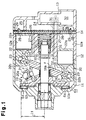
- a front housing member 11 is coupled to the front (left in Fig. 1) of a cylinder block 12.
- a rear housing member 13 is coupled to the rear (right in Fig. 1) of the cylinder block 12 through a valve plate 14.
- the front housing member 11, the cylinder block 12, and the rear housing member 13 form a compressor housing.
- a crank chamber 15 is defined between the front housing member 11 and the cylinder block 12.
- a drive shaft 16 passes through the crank chamber 15 and is supported by the front housing member 11 and the cylinder block 12.
- a rotor, or lug plate 17 is fixed to the drive shaft 16 in the crank chamber 15.
- a cam plate, which is a swash plate 18 in this embodiment, is located in the crank chamber 15.
- the drive shaft 16 passes through a central hole 18a of the swash plate 18.
- a hinge mechanism 19 is located between the lug plate 17 and the swash plate 18.
- two guide pins 20 of the hinge mechanism 19 are formed on the front surface of the swash plate 18 and are symmetrical to one another with respect to a plane that includes the axis L and a line D1.
- the line D1 marks a top dead center location on the swash plate 18.
- a spherical portion 20a is formed in the distal end of each guide pin 20.
- Two support arms 21 are formed on the rear surface of the lug plate 17 and are symmetrical to with respect to the previously mentioned plane.
- a guide hole 21a is formed in the distal end of each support arm 21 as shown in Fig. 1.
- the spherical portions 20a are received in the corresponding guide holes 21a and engage the cylindrical walls of the guide holes 21a.
- the spherical portions 20a slide in the corresponding guide holes 21a, and the swash plate 18 is supported by the drive shaft 16 through the central hole 18a. Accordingly, the swash plate 18 slides on the surface of the drive shaft 16 and inclines relative to the drive shaft 16.
- Cylinder bores 12a are formed in the cylinder block 12 and equally spaced from the axis L at predetermined angular intervals.
- Each piston 22 includes a head 22a, which is accommodated in the corresponding cylinder bore 12a, and a neck 22b, which is coupled to the periphery of the swash plate 18 through shoes 23. Rotation of the drive shaft 16 is converted into reciprocation of the pistons 22 through the swash plate 18 and the shoes 23.
- a suction chamber 24 and a discharge chamber 25 are formed in the rear housing member 13, respectively.
- the valve plate 14 includes suction ports 26, suction valves 27, discharge ports 28, and discharge valves 29.
- refrigerant gas in the suction chamber 24 is drawn to the cylinder bores 12a through the corresponding suction ports 26 and suction valves 27 by the movement of the pistons 22 from the top dead center to the bottom dead center. Then, movement of the pistons 22 from the bottom dead center to the top dead center compresses the refrigerant gas in the cylinder bores 12a to a certain pressure and discharges the refrigerant gas to the discharge chamber 25 through the corresponding discharge ports 28 and discharge valves 29.
- a bleed passage 30 connects the crank chamber 15 to the suction chamber 24.
- a pressurizing passage 31 connects the discharge chamber 25 to the crank chamber 15.
- a displacement control valve 32 is located in the pressurizing passage 31. The control valve 32 adjusts the opening size of the pressurizing passage 31, which adjusts the flow rate of high-pressure gas from the discharge chamber 25 to the crank chamber 15. The relationship between the flow rate of gas into the crank chamber 15 and the flow rate of gas released from the crank chamber 15 to the suction chamber 24 determines the pressure in the crank chamber 15. When the pressure in the crank chamber 15 is varied, the difference between the pressure in the crank chamber 15 and the pressure in the cylinder bores 12a is varied, which varies the inclination of the swash plate 18 and adjusts the compressor displacement.
- an annular thrust bearing 61 is located between the lug plate 17 and an inner wall 11a of the front housing member 11.
- the thrust bearing 61 is centered about the axis L of the drive shaft 16.
- the thrust bearing 61 receives a compression load F applied from the pistons 22 to the lug plate 17 through the swash plate 18 and the hinge mechanism 19.
- the thrust bearing 61 includes a rear annular race 62, which is fixed to the lug plate 17, a front annular race 63 fixed to the wall 11a of the front housing member 11, and rollers 64 (only two are shown), which are between the races 62, 63.
- the rollers 64 are radially arranged about the axis L.
- the front race 64 rotates relative to the rear race 62 when the lug plate 17 rotates. Accordingly, the rollers 64 rotate about the axis L while the lug plate 17 rotates.
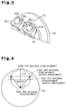
- the thrust bearing 61 receives the compression load F within the radius 11.
- the radius 11 is greater than the distance 12, which is between the place of engagement S and the axis L when the swash plate 18 is at the maximum inclination position.
- the radius 11 corresponds to the radius of a circle drawn by the outermost points of contact between the races 62, 63 and the rollers 64.
- the stop member 35 does not contact the lug plate 17. Accordingly, the compression load F from the swash plate 18 is applied to the lug plate 17 only through the place of engagement S (the magnitude of the compression load F and the location of the place of engagement S may be considered to be the same as those when the displacement is maximized). Therefore, the compression load F is transmitted to the lug plate 17 in an unbalanced manner with respect to the axis L.
- the radius 11 of the thrust bearing 61 is greater than the distance 12 between the place of engagement S and the axis L when the inclination of the swash plate 18 is maximized. Even if the compression load F is transmitted to the lug plate 17 only through the place of engagement S when the displacement becomes less than the maximum displacement, the places of engagement S remain within the radius 11. As a result, the lug plate 17 properly receives the compression load F and is not inclined by an inclination moment based on the compression load F. This prevents noise and vibration of the compressor.
- the swash plate 18 is supported by the drive shaft 16 in a different manner, and the structure of a hinge mechanism 71 is different, compared to the hinge mechanism 19 of the first embodiment.
- a sleeve 72 slides axially on the drive shaft 16.
- Two support pins 73 (only one shown) are located on opposite sides of the sleeve 72.
- the support pins 73 define a pivot axis that is perpendicular to the axis L.
- the swash plate 18 is supported by the sleeve 72 through the support pins 73, and the inclination of the swash plate 18 varies.
- a support arm 75 is formed on the rear of the lug plate 17 at a location corresponding to a top dead center line D1 of a swash plate 18.
- An elongated guide hole 75a passes through the distal end of the support arm 75 in as shown in Fig. 5.
- a link pin 74 which is located in front of the line D1, engages the guide hole 75a of the support arm 75. The pin 74 is supported by the swash plate 18 as shown in Fig. 5.
- the guide hole 75a guides the link pin 74.
- the sleeve 72 supports the swash plate 18 and slides on the drive shaft 16. Accordingly, the swash plate 18 moves axially and inclines with respect to the drive shaft 16.
- the sleeve 72 moves toward the cylinder block 12, the inclination of the swash plate 18 decreases.
- the place of engagement S (a line of contact between the link pin 74 and the guide hole 75a as shown in Fig. 5) moves toward the axis L along the guide hole 75a.
- a front part of the sleeve 72 is a stop member.
- the radius 11 of the thrust bearing 61 is greater than the distance 12 between the place of engagement S and the axis L when the inclination of the swash plate 18 is maximized as shown in Fig. 5. Accordingly, the present invention has the same operation and advantages as the first embodiment.
- the guide pins 20 (and the spherical portions 20a) may be fixed to the lug plate 17, and the support arms 21 (and the guide holes 21a) may be formed on the swash plate 18.
- the link pin 74 may be formed on the lug plate 17, and the support arm 75 (and the guide hole 75a) may be formed on the swash plate 18.
- only one guide pin 20 (and one spherical portion 20a) and one support arm 21 (and one guide hole 21a) may be employed.
- At least one of the races 62, 63 may be omitted from the thrust bearing 61.
- the rollers 64 directly roll on the front surface of the lug plate 17 or the inner wall 11a of the front housing member 11. This reduces the number of parts.
- the rollers 64 of the thrust bearing 61 may be balls.
- the thrust bearing is not limited to roller bearing and may be a slide bearing without rollers.
- the present invention may be applied to a wobble-type variable displacement compressor.
- a variable displacement compressor that prevents inclination of a lug plate when the displacement is less than the maximum displacement.
- a thrust bearing 61 is located between the lug plate 17 and the front housing member 11. The thrust bearing 61 is annular and centered on the axis L of the drive shaft 16. The thrust bearing 61 receives a compression load F applied to the lug plate 17 from pistons 22 through a swash plate 18 and a hinge mechanism 19. The radius 11 of the thrust bearing 61 is greater than the distance between the contact point of the hinge mechanism 19 and the axis L of the drive shaft 16 when the inclination of the swash plate 18 is maximized. Therefore, the compression load F is applied within the radius of the thrust bearing, which reduces noise and vibration.
Landscapes
- Engineering & Computer Science (AREA)
- Mechanical Engineering (AREA)
- General Engineering & Computer Science (AREA)
- Compressors, Vaccum Pumps And Other Relevant Systems (AREA)
Abstract
A variable displacement compressor that prevents inclination of a lug plate when the displacement is less than the maximum displacement. A thrust bearing 61 is located between the lug plate 17 and the front housing member 11. The thrust bearing 61 is annular and centered on the axis L of the drive shaft 16. The thrust bearing 61 receives a compression load F applied to the lug plate 17 from pistons 22 through a swash plate 18 and a hinge mechanism 19. The radius 11 of the thrust bearing 61 is greater than the distance between the contact point of the hinge mechanism 19 and the axis L of the drive shaft 16 when the inclination of the swash plate 18 is maximized. Therefore, the compression load F is applied within the radius of the thrust bearing, which reduces noise and vibration. <IMAGE>
Description
The present invention relates to a variable
displacement compressor for air-conditioning vehicles.
Fig. 6 shows such a variable displacement compressor
(simply called compressor herein). The compressor of Fig. 6
has a housing 102, which includes a crank chamber 101. A
drive shaft 103 is supported by the housing 102 and passes
through the crank chamber 101. A lug plate 104 is fixed to
the drive shaft 103 in the crank chamber 101. A swash plate
105 slides on the drive shaft 103 and inclines relative to
the axis L of the drive shaft 103.
A hinge mechanism 106 is located between the lug plate
104 and the swash plate 105. The hinge mechanism 106
includes a guide pin 111 and a support arm 112. The guide
pin 111, which is formed on the swash plate 105, includes a
spherical portion 111a. The support arm 112, which is formed
on the lug plate 104, includes a guide hole 112a for
receiving the spherical portion 111a. The hinge mechanism
106 causes the swash plate 105 to rotate integrally with the
drive shaft 103 and permits the swash plate 105 to incline
with respect to the drive shaft 103.
A thrust bearing 109 is located between the lug plate
104 and an inner wall 102a of the housing 102. The thrust
bearing 109 receives a compression force F applied to the lug
plate 104 from the pistons 107 through the swash plate 105
and the hinge mechanism 106.
The compressor displacement is adjusted by varying the
inclination of the swash plate 105. The hinge mechanism 106
permits the inclination of the swash plate 105 to vary, which
varies the stroke of the pistons 107, that is, the compressor
displacement. The maximum inclination of the swash plate 105
is determined by abutment of the swash plate 105 against the
lug plate 104. More specifically, a stop member 110, which
is diametrically opposite to the hinge mechanism 106 with
respect to the axis L, contacts the lug plate 104.
The compression load F is maximized when the compressor
displacement is maximized. At the maximum displacement (see
Fig. 6), the compression load F is transmitted from the swash
plate 105 to the lug plate 104 through a place of engagement
S (the contact point between the spherical portion 111a and
the guide hole 112a) and the stop member 110. Accordingly,
the compression load F is transmitted to the lug plate 104 at
opposite sides of the axis L, which prevents a moment based
on the compression load F from inclining the lug plate 104
relative to the drive shaft 103.
When the compressor displacement is less than the
maximum displacement, the stop member 110 does not contact
the lug plate 104. Accordingly, the compression load F
(about the same as that when the displacement is maximized)
is transmitted from the swash plate 105 to the lug plate 104
only through the place of engagement S of the hinge mechanism
106. Therefore, the transmission of the compression load F
to the lug plate 104 is unbalanced about the axis L.
The thrust bearing 109 is annular and receives the
compression load F within the radius 11. However, the radius
11 is less than the distance between the place of engagement
S and the axis L when the inclination of the swash plate 105
is maximized. Accordingly, the thrust bearing 109 does not
receive the compression load F from the place of engagement S
within the radius 11 when the swash plate 105 is greatly
inclined and the stop member 110 does not contact the lug
plate 104.
When the displacement is less than the maximum
displacement, an inclination moment based on the compression
load F is applied to the lug plate 104, which inclines the
lug plate 104 and increases the size of a gap between the
inner wall 102a and the lug plate 104. As a result, the
thrust bearing 109 chatters when the lug plate 104 rotates.
This may cause noise and vibration of the compressor.
An objective of the present invention is to provide a
variable displacement compressor that prevents the
inclination of the lug plate when the compressor displacement
is less than maximum displacement.
To achieve the above objective, the present invention
provides a variable displacement type compressor structured
as follows. A housing includes a housing member and a
cylinder block having a cylinder bore. A crank chamber is
formed in the housing. A drive shaft is supported by the
housing member and the cylinder block. The drive shaft
passes through the crank chamber. A piston is accommodated
in the cylinder bore formed in the cylinder block. The
piston is connected to a cam plate. The cam plate converts
rotation of the drive shaft into reciprocation of the piston
to cause the piston to perform a gas compression operation.
The cam plate inclines with respect to the drive shaft. The
displacement of the compressor varies in accordance with the
inclination of the cam plate. A rotor is fixed to the drive
shaft and located in the crank chamber. A hinge mechanism
connects the cam plate to the rotor so that the cam plate is
driven by the rotor. The hinge mechanism permits the
inclination angle of the cam plate to vary. The position of
a place of engagement in the hinge mechanism between the cam
plate and the rotor varies according to the inclination of
the cam plate. A stop member is connected to the cam plate.
The stop member restricts the inclination of the cam plate
when the stop member contacts the rotor. An annular thrust
bearing is located in the crank chamber between the rotor and
the housing member. The thrust bearing receives a
compression load acting on the rotor. The compression load
results from the compression of gas by the piston. The
radius of the outermost force-transmitting points of the
thrust bearing is equal to or greater than the radial
distance between the place of engagement and the axis of the
drive shaft when the inclination angle of the cam plate is
maximum.
Other aspects and advantages of the invention will
become apparent from the following description, taken in
conjunction with the accompanying drawings, illustrating by
way of example the principles of the invention.
The invention, together with objects and advantages
thereof, may best be understood by reference to the following
description of the presently preferred embodiments together
with the accompanying drawings in which:
First and second embodiments of the present invention
will be described in the following. The description of the
second embodiment will focus on differences from the first
embodiment.
As shown in Fig. 1, a front housing member 11 is
coupled to the front (left in Fig. 1) of a cylinder block 12.
A rear housing member 13 is coupled to the rear (right in Fig.
1) of the cylinder block 12 through a valve plate 14. The
front housing member 11, the cylinder block 12, and the rear
housing member 13 form a compressor housing. A crank chamber
15 is defined between the front housing member 11 and the
cylinder block 12. A drive shaft 16 passes through the crank
chamber 15 and is supported by the front housing member 11
and the cylinder block 12.
A rotor, or lug plate 17, is fixed to the drive shaft
16 in the crank chamber 15. A cam plate, which is a swash
plate 18 in this embodiment, is located in the crank chamber
15. The drive shaft 16 passes through a central hole 18a of
the swash plate 18. A hinge mechanism 19 is located between
the lug plate 17 and the swash plate 18.
As shown in Figs. 1 and 3, two guide pins 20 of the
hinge mechanism 19 are formed on the front surface of the
swash plate 18 and are symmetrical to one another with
respect to a plane that includes the axis L and a line D1.
The line D1 marks a top dead center location on the swash
plate 18. When one of a plurality of pistons 22 is axially
aligned with the line D1, that piston 22 is in its top dead
center position. A spherical portion 20a is formed in the
distal end of each guide pin 20. Two support arms 21 are
formed on the rear surface of the lug plate 17 and are
symmetrical to with respect to the previously mentioned plane.
A guide hole 21a is formed in the distal end of each support
arm 21 as shown in Fig. 1. The spherical portions 20a are
received in the corresponding guide holes 21a and engage the
cylindrical walls of the guide holes 21a.
The spherical portions 20a slide in the corresponding
guide holes 21a, and the swash plate 18 is supported by the
drive shaft 16 through the central hole 18a. Accordingly,
the swash plate 18 slides on the surface of the drive shaft
16 and inclines relative to the drive shaft 16.
As shown in Fig. 2, when the center of the swash plate
18 moves toward the cylinder block 12, the inclination of the
swash plate decreases. At this time, the spherical portions
20a move toward the axis L in the corresponding guide holes
21a. That is, the places of engagement S of the hinge
mechanism 19 (the contact points between each spherical
portion 20a and the corresponding guide hole 21a) move toward
the axis L.
As shown in Fig. 1, when the center of the swash plate
18 moves toward the lug plate 17, the inclination of the
swash plate 18 increases. At this time, the spherical
portions 20a move away from the axis L in the corresponding
guide holes 21a. The maximum inclination of the swash plate
18 is determined by abutment of a stop member 35 against the
lug plate 17. The stop member 35 of the swash plate 18 is
substantially diametrically opposite to the hinge mechanism
19 with respect to the axis L and is located in the vicinity
of a line D2 of the swash plate 18. The line D2 marks a
bottom dead center location on the swash plate 18, that is, a
piston 22 is in its bottom dead center position when axially
aligned with the line D2.
Cylinder bores 12a (only two are shown) are formed in
the cylinder block 12 and equally spaced from the axis L at
predetermined angular intervals. Each piston 22 includes a
head 22a, which is accommodated in the corresponding cylinder
bore 12a, and a neck 22b, which is coupled to the periphery
of the swash plate 18 through shoes 23. Rotation of the
drive shaft 16 is converted into reciprocation of the pistons
22 through the swash plate 18 and the shoes 23.
A suction chamber 24 and a discharge chamber 25 are
formed in the rear housing member 13, respectively. The
valve plate 14 includes suction ports 26, suction valves 27,
discharge ports 28, and discharge valves 29. When the drive
shaft 16 is rotated by an external drive source such as a
vehicle engine (not shown), refrigerant gas in the suction
chamber 24 is drawn to the cylinder bores 12a through the
corresponding suction ports 26 and suction valves 27 by the
movement of the pistons 22 from the top dead center to the
bottom dead center. Then, movement of the pistons 22 from
the bottom dead center to the top dead center compresses the
refrigerant gas in the cylinder bores 12a to a certain
pressure and discharges the refrigerant gas to the discharge
chamber 25 through the corresponding discharge ports 28 and
discharge valves 29.
A bleed passage 30 connects the crank chamber 15 to the
suction chamber 24. A pressurizing passage 31 connects the
discharge chamber 25 to the crank chamber 15. A displacement
control valve 32 is located in the pressurizing passage 31.
The control valve 32 adjusts the opening size of the
pressurizing passage 31, which adjusts the flow rate of high-pressure
gas from the discharge chamber 25 to the crank
chamber 15. The relationship between the flow rate of gas
into the crank chamber 15 and the flow rate of gas released
from the crank chamber 15 to the suction chamber 24
determines the pressure in the crank chamber 15. When the
pressure in the crank chamber 15 is varied, the difference
between the pressure in the crank chamber 15 and the pressure
in the cylinder bores 12a is varied, which varies the
inclination of the swash plate 18 and adjusts the compressor
displacement.
The advantages of the first embodiment will now be
described.
As shown in Fig. 1, an annular thrust bearing 61 is
located between the lug plate 17 and an inner wall 11a of the
front housing member 11. The thrust bearing 61 is centered
about the axis L of the drive shaft 16. The thrust bearing
61 receives a compression load F applied from the pistons 22
to the lug plate 17 through the swash plate 18 and the hinge
mechanism 19.
The thrust bearing 61 includes a rear annular race 62,
which is fixed to the lug plate 17, a front annular race 63
fixed to the wall 11a of the front housing member 11, and
rollers 64 (only two are shown), which are between the races
62, 63. The rollers 64 are radially arranged about the axis
L. The front race 64 rotates relative to the rear race 62
when the lug plate 17 rotates. Accordingly, the rollers 64
rotate about the axis L while the lug plate 17 rotates.
As shown in Figs. 1 and 4, the thrust bearing 61
receives the compression load F within the radius 11. The
radius 11 is greater than the distance 12, which is between
the place of engagement S and the axis L when the swash plate
18 is at the maximum inclination position. The radius 11
corresponds to the radius of a circle drawn by the outermost
points of contact between the races 62, 63 and the rollers 64.
As shown in Fig. 1, when the compressor displacement is
maximized, the compression load F from the swash plate 18 is
applied to the lug plate 17 through the place of engagement S
and the stop member 35. Accordingly, the application of the
compression load F is relatively balanced on the lug plate 17
with respect to the axis L. This prevents a significantly
great inclination moment based on the compression load F from
being applied to the lug plate 17.
However, when the compressor displacement becomes less
than the maximum displacement, the stop member 35 does not
contact the lug plate 17. Accordingly, the compression load
F from the swash plate 18 is applied to the lug plate 17 only
through the place of engagement S (the magnitude of the
compression load F and the location of the place of
engagement S may be considered to be the same as those when
the displacement is maximized). Therefore, the compression
load F is transmitted to the lug plate 17 in an unbalanced
manner with respect to the axis L.
The radius 11 of the thrust bearing 61 is greater than
the distance 12 between the place of engagement S and the
axis L when the inclination of the swash plate 18 is
maximized. Even if the compression load F is transmitted to
the lug plate 17 only through the place of engagement S when
the displacement becomes less than the maximum displacement,
the places of engagement S remain within the radius 11. As a
result, the lug plate 17 properly receives the compression
load F and is not inclined by an inclination moment based on
the compression load F. This prevents noise and vibration of
the compressor.
To avoid a redundant description, like or same
reference numerals are given to those components that are the
same as the corresponding components of the first embodiment.
As shown in Fig. 5, in a second embodiment, the swash
plate 18 is supported by the drive shaft 16 in a different
manner, and the structure of a hinge mechanism 71 is
different, compared to the hinge mechanism 19 of the first
embodiment.
A sleeve 72 slides axially on the drive shaft 16. Two
support pins 73 (only one shown) are located on opposite
sides of the sleeve 72. The support pins 73 define a pivot
axis that is perpendicular to the axis L. The swash plate 18
is supported by the sleeve 72 through the support pins 73,
and the inclination of the swash plate 18 varies.
A support arm 75 is formed on the rear of the lug plate
17 at a location corresponding to a top dead center line D1
of a swash plate 18. An elongated guide hole 75a passes
through the distal end of the support arm 75 in as shown in
Fig. 5. A link pin 74, which is located in front of the line
D1, engages the guide hole 75a of the support arm 75. The
pin 74 is supported by the swash plate 18 as shown in Fig. 5.
The guide hole 75a guides the link pin 74. The sleeve
72 supports the swash plate 18 and slides on the drive shaft
16. Accordingly, the swash plate 18 moves axially and
inclines with respect to the drive shaft 16. When the sleeve
72 moves toward the cylinder block 12, the inclination of the
swash plate 18 decreases. At this time, the place of
engagement S (a line of contact between the link pin 74 and
the guide hole 75a as shown in Fig. 5) moves toward the axis
L along the guide hole 75a.
When the sleeve 72 moves toward the lug plate 17, the
inclination of the swash plate 18 increases. At this time,
the place of engagement S moves away from the axis L along
the guide hole 75a. The maximum inclination of the swash
plate 18 is determined by the abutment of the sleeve 72
against the lug plate 17. Therefore, a front part of the
sleeve 72 is a stop member.
The radius 11 of the thrust bearing 61 is greater than
the distance 12 between the place of engagement S and the
axis L when the inclination of the swash plate 18 is
maximized as shown in Fig. 5. Accordingly, the present
invention has the same operation and advantages as the first
embodiment.
Although only two embodiments of the present invention
have been described herein, it should be apparent to those
skilled in the art that the present invention may be embodied
in many other specific forms without departing from the
spirit or scope of the invention. Particularly, it should be
understood that the invention may be embodied in the
following forms.
In the hinge mechanism 19 of the first embodiment, the
guide pins 20 (and the spherical portions 20a) may be fixed
to the lug plate 17, and the support arms 21 (and the guide
holes 21a) may be formed on the swash plate 18.
In the hinge mechanism 71 of the second embodiment, the
link pin 74 may be formed on the lug plate 17, and the
support arm 75 (and the guide hole 75a) may be formed on the
swash plate 18.
In the hinge mechanism 19 of the first embodiment, only
one guide pin 20 (and one spherical portion 20a) and one
support arm 21 (and one guide hole 21a) may be employed.
At least one of the races 62, 63 may be omitted from
the thrust bearing 61. In this case, the rollers 64 directly
roll on the front surface of the lug plate 17 or the inner
wall 11a of the front housing member 11. This reduces the
number of parts.
The rollers 64 of the thrust bearing 61 may be balls.
The thrust bearing is not limited to roller bearing and may
be a slide bearing without rollers.
The present invention may be applied to a wobble-type
variable displacement compressor.
Therefore, the present examples and embodiments are to
be considered as illustrative and not restrictive and the
invention is not to be limited to the details given herein,
but may be modified within the scope and equivalence of the
appended claims.
A variable displacement compressor that prevents
inclination of a lug plate when the displacement is less than
the maximum displacement. A thrust bearing 61 is located
between the lug plate 17 and the front housing member 11.
The thrust bearing 61 is annular and centered on the axis L
of the drive shaft 16. The thrust bearing 61 receives a
compression load F applied to the lug plate 17 from pistons
22 through a swash plate 18 and a hinge mechanism 19. The
radius 11 of the thrust bearing 61 is greater than the
distance between the contact point of the hinge mechanism 19
and the axis L of the drive shaft 16 when the inclination of
the swash plate 18 is maximized. Therefore, the compression
load F is applied within the radius of the thrust bearing,
which reduces noise and vibration.
Claims (8)
- A variable displacement compressor comprising: a housing having a housing member (11) and a cylinder block (12); a crank chamber (15) formed in the housing; a drive shaft (16) supported by the housing member and the cylinder block so as to pass through the crank chamber; a plurality of pistons (22) accommodated in cylinder bores (12a) formed in the cylinder block; a cam plate (18) to which the pistons are connected, the cam plate converting rotation of the drive shaft into reciprocation of the pistons to cause the pistons to perform a gas compression operation, wherein the cam plate inclines with respect to the drive shaft, and the displacement of the compressor varies in accordance with the inclination of the cam plate; a rotor (17) fixed to the drive shaft and located in the crank chamber; a hinge mechanism (19, 71) for connecting the cam plate to the rotor so that the cam plate is driven by the rotor, wherein the hinge mechanism permits the inclination angle of the cam plate to vary, wherein the position of a place of engagement in the hinge mechanism between the cam plate and the rotor varies according to the inclination of the cam plate; a stop member (35, 72) connected to the cam plate for restricting the inclination of the cam plate when the stop member contacts the rotor; and an annular thrust bearing (61) located in the crank chamber between the rotor and the housing member, so as to receive a compression load acting on the rotor according to the compression of gas by the piston, characterized in that the radius (11) of the outermost force-transmitting points of the thrust bearing is equal to or greater than the radial distance between the place of engagement (S) and the axis (L) of the drive shaft when the inclination angle of the cam plate is maximum.
- The variable displacement compressor according to claim 1, wherein the hinge mechanism (19) includes a spherical portion (20a), which is fixed to one of the rotor and the cam plate, and a guide hole (21a) provided in the other of the rotor and the cam plate, wherein the spherical portion is received by the guide hole and slides on a wall defining the guide hole, and wherein the place of engagement (S) is a point of contact between the spherical portion and the wall defining the guide hole.
- The variable displacement compressor according to claim 2, wherein the hinge mechanism (19) includes a pair of spherical portions (20a) and a pair of guide holes (21a).
- The variable displacement compressor according to any one of claims 1 to 3, wherein the stop member (35) is formed on the cam plate.
- The variable displacement compressor according to claim 1 further comprising:an elongated guide hole (75a) formed in a member that is fixed to one of the rotor and the cam plate; anda link pin (74) fixed to the other of the rotor and the cam plate, wherein the link pin is received by the guide hole, and wherein the place of engagement (S) is a line of contact between the link pin and a surface defining the guide hole.
- The variable displacement compressor according to claim 1 or 5, further comprising a sleeve (72) for supporting the cam plate (18), wherein the sleeve slides on the drive shaft (16), and wherein the stop member is a part of the sleeve.
- The variable displacement compressor according to claim 1, 2, 3 or 5, wherein the thrust bearing (61) is a roller bearing and comprises a race (62) fixed to the rotor (17), a race (63) fixed to an inner wall surface of the housing member (11), and rolling elements (64) located between the races.
- The variable displacement compressor according to claim 7, wherein the rolling elements include rollers.
Applications Claiming Priority (2)
| Application Number | Priority Date | Filing Date | Title |
|---|---|---|---|
| JP11192694A JP2001020858A (en) | 1999-07-07 | 1999-07-07 | Variable displacement type compressor |
| JP19269499 | 1999-07-07 |
Publications (1)
| Publication Number | Publication Date |
|---|---|
| EP1067288A2 true EP1067288A2 (en) | 2001-01-10 |
Family
ID=16295505
Family Applications (1)
| Application Number | Title | Priority Date | Filing Date |
|---|---|---|---|
| EP00114538A Withdrawn EP1067288A2 (en) | 1999-07-07 | 2000-07-06 | Thrust bearing for the swash plate of a compressor |
Country Status (5)
| Country | Link |
|---|---|
| EP (1) | EP1067288A2 (en) |
| JP (1) | JP2001020858A (en) |
| KR (1) | KR20010014520A (en) |
| CN (1) | CN1283743A (en) |
| BR (1) | BR0002354A (en) |
Families Citing this family (4)
| Publication number | Priority date | Publication date | Assignee | Title |
|---|---|---|---|---|
| JP2003065224A (en) | 2001-08-28 | 2003-03-05 | Toyota Industries Corp | Variable displacement piston compressor |
| AU2009335645A1 (en) * | 2008-12-18 | 2011-07-14 | S.P.M. Flow Control, Inc. | Suction port lock nut with stub buttress threads |
| US9157468B2 (en) | 2010-06-04 | 2015-10-13 | S.P.M. Flow Control, Inc. | Packing nut lock and method of use |
| CN102926967B (en) * | 2012-11-23 | 2015-03-11 | 上海威乐汽车空调器有限公司 | Reciprocating type tilting tray compressor structure |
-
1999
- 1999-07-07 JP JP11192694A patent/JP2001020858A/en active Pending
-
2000
- 2000-02-29 KR KR1020000010174A patent/KR20010014520A/en not_active Ceased
- 2000-06-14 BR BR0002354-0A patent/BR0002354A/en not_active IP Right Cessation
- 2000-07-06 EP EP00114538A patent/EP1067288A2/en not_active Withdrawn
- 2000-07-06 CN CN00119995A patent/CN1283743A/en active Pending
Non-Patent Citations (1)
| Title |
|---|
| None |
Also Published As
| Publication number | Publication date |
|---|---|
| KR20010014520A (en) | 2001-02-26 |
| CN1283743A (en) | 2001-02-14 |
| BR0002354A (en) | 2001-03-13 |
| JP2001020858A (en) | 2001-01-23 |
Similar Documents
| Publication | Publication Date | Title |
|---|---|---|
| US6139282A (en) | Variable capacity refrigerant compressor with an aluminum cam plate means | |
| US6158968A (en) | Fluid displacement apparatus with variable displacement mechanism | |
| US20090064855A1 (en) | Capacity-variable type swash plate compressor | |
| US5931079A (en) | Variable capacity swash plate compressor | |
| US6629823B2 (en) | Compressors | |
| KR19980070248A (en) | Variable displacement compressor | |
| US5556261A (en) | Piston type compressor | |
| US6338613B1 (en) | Piston-type compressor | |
| EP0853198A2 (en) | Swash-plate compressor in which improvement is made as regards a connection mechanism between a piston and a swash plate | |
| US20010028851A1 (en) | Variable displacement compressors | |
| US5771775A (en) | Device for guiding a piston | |
| US6446540B1 (en) | Bearing for swash plate compressor | |
| US5882179A (en) | Compressor with bearing between the drive shaft and the swash-plate boss | |
| JPH04318291A (en) | Variable displacement swash plate type compressor | |
| EP1783369A1 (en) | Compressor | |
| US20170145997A1 (en) | Variable displacement type swash plate compressor | |
| EP1043500A2 (en) | Pivot joint for a swash plate of a variable displacement compressor | |
| KR20010014520A (en) | Variable displacement compressor | |
| US20050265855A1 (en) | Piston type compressor | |
| US10072648B2 (en) | Variable displacement type swash plate compressor | |
| EP1275846B1 (en) | Hinge for a swash plate | |
| US20020018726A1 (en) | Compressor | |
| EP1164291A2 (en) | Swash plate compressor | |
| US6912948B2 (en) | Swash plate compressor | |
| JPH0472071B2 (en) |
Legal Events
| Date | Code | Title | Description |
|---|---|---|---|
| PUAI | Public reference made under article 153(3) epc to a published international application that has entered the european phase |
Free format text: ORIGINAL CODE: 0009012 |
|
| 17P | Request for examination filed |
Effective date: 20000706 |
|
| AK | Designated contracting states |
Kind code of ref document: A2 Designated state(s): AT BE CH CY DE DK ES FI FR GB GR IE IT LI LU MC NL PT SE |
|
| AX | Request for extension of the european patent |
Free format text: AL;LT;LV;MK;RO;SI |
|
| RAP1 | Party data changed (applicant data changed or rights of an application transferred) |
Owner name: KABUSHIKI KAISHA TOYOTA JIDOSHOKKI |
|
| STAA | Information on the status of an ep patent application or granted ep patent |
Free format text: STATUS: THE APPLICATION IS DEEMED TO BE WITHDRAWN |
|
| 18D | Application deemed to be withdrawn |
Effective date: 20030201 |