EP1067087A2 - Tilt control device for fork lift truck - Google Patents
Tilt control device for fork lift truck Download PDFInfo
- Publication number
- EP1067087A2 EP1067087A2 EP00114420A EP00114420A EP1067087A2 EP 1067087 A2 EP1067087 A2 EP 1067087A2 EP 00114420 A EP00114420 A EP 00114420A EP 00114420 A EP00114420 A EP 00114420A EP 1067087 A2 EP1067087 A2 EP 1067087A2
- Authority
- EP
- European Patent Office
- Prior art keywords
- valve
- tilt
- pilot
- flow rate
- rate control
- Prior art date
- Legal status (The legal status is an assumption and is not a legal conclusion. Google has not performed a legal analysis and makes no representation as to the accuracy of the status listed.)
- Granted
Links
- 239000003921 oil Substances 0.000 claims abstract description 35
- 239000010720 hydraulic oil Substances 0.000 claims abstract description 27
- 238000012217 deletion Methods 0.000 claims abstract description 13
- 230000037430 deletion Effects 0.000 claims abstract description 13
- 238000004891 communication Methods 0.000 claims description 3
- 238000010276 construction Methods 0.000 description 6
- 238000001514 detection method Methods 0.000 description 6
- 230000001276 controlling effect Effects 0.000 description 5
- 238000000034 method Methods 0.000 description 3
- 230000007935 neutral effect Effects 0.000 description 2
- 230000001105 regulatory effect Effects 0.000 description 2
- 238000007796 conventional method Methods 0.000 description 1
- 238000010586 diagram Methods 0.000 description 1
- 238000006073 displacement reaction Methods 0.000 description 1
- 230000000694 effects Effects 0.000 description 1
Images


Classifications
-
- B—PERFORMING OPERATIONS; TRANSPORTING
- B66—HOISTING; LIFTING; HAULING
- B66F—HOISTING, LIFTING, HAULING OR PUSHING, NOT OTHERWISE PROVIDED FOR, e.g. DEVICES WHICH APPLY A LIFTING OR PUSHING FORCE DIRECTLY TO THE SURFACE OF A LOAD
- B66F9/00—Devices for lifting or lowering bulky or heavy goods for loading or unloading purposes
- B66F9/06—Devices for lifting or lowering bulky or heavy goods for loading or unloading purposes movable, with their loads, on wheels or the like, e.g. fork-lift trucks
- B66F9/075—Constructional features or details
- B66F9/20—Means for actuating or controlling masts, platforms, or forks
- B66F9/22—Hydraulic devices or systems
Definitions
- the present invention relates to a tilt control technique for controlling the tilting operation of masts of a fork lift truck, and more particularly to the flow rate control of a hydraulic control valve for controlling the operation of a tilt cylinder.
- a tilt cylinder control device comprising a forward tilting angle control function for putting limitations on the forward tilting angle of masts depending on lift height and/or load when the masts are tilted forward and a rearward tilting speed control function for slowing the rearward tilting speed of the masts when the masts are tilted rearward under a high lift height and high loaded condition.
- These controls can be attained by providing on a passage connecting a rod side oil chamber of a tilt cylinder for tilting the mast with a tilt spool for operating the tilt cylinder a control valve capable of regulating the flow rate of hydraulic oil and of stopping a tilt cylinder at a predetermined position within its range of stroke.
- a tilt control device comprising a control valve as described above is disclosed in, for example, Japanese Patent Laid-open No. 10-330096.
- a proportional electromagnetic type flow rate control valve is provided on the aforesaid passage, and the proportional electromagnetic type flow rate control valve comprises a flow rate control part and a solenoid part for generating a pilot pressure, wherein the pilot pressure acting on the flow rate control part is controlled with an electromagnetic force (which is in proportion to current flowing through the coil) generated at the solenoid part, and wherein the displacement (opening) of a spool of the flow rate control part is determined by the balance between the pilot pressure and a spring force, whereby a flow rate in proportion to current is obtained.
- the present invention has been made in view of the above problem, and an object thereof is to provide a tilt control technique for simplifying the construction of a tilt control device and for reducing cost for producing the same, while ensuring that the conventional masts forward tilting angle control function and rearward tilting speed control function are maintained.
- a tilt control device for a fork lift truck for allowing hydraulic oil received in a tank to flow into one of a rod side oil compartment and a bottom side oil compartments of a tilt cylinder using a hydraulic pump for tilting masts of the fork lift truck, the control device comprising:
- the electromagnetic switching valve for pilot operation when operated for switching, the pilot pressure is added or deleted relative to the flow rate control valve, whereby the flow rate control valve is switched to its fully opened position or half opened position.
- This switching of the flow rate control valve then leads to the control of the amount of hydraulic oil for the rod side oil compartment of the tilt cylinder in two ways; large and small, whereby the operating speed of the tilt cylinder is in turn switched between two speeds; high and low.
- the electromagnetic switching valve is operated for switching in response to respective detection signals representing rearward tilting operation, high lift height and high load, and the flow rate control valve is then switched from the fully opened position to the half opened position, thereby making it possible to control the rearward tilting speed of the masts.
- the pilot operation type changeover valve is changed over to a position where a pilot pressure is added or to another position where the pilot pressure is deleted relative to a poppet valve for an opening or closing operation, and this changing over of the positions of the changeover valve results in opening or closing of the poppet valve.
- the hydraulic oil in the rod side oil compartment is permitted to or prohibited from flowing out thereof by operating the electromagnetic switching valve for switching, whereby the tilt cylinder is put in operation or brought to a stop.
- the forward tilting angle can be controlled by switching the electromagnetic switching valve to a position to stop the operation of the tilt cylinder in response to detection signals representing forward tilting operation, high lift height and high load, and additionally a detection signal representing that the tilt angle of the masts reaches a given value.
- a fork lift truck can be provided which is fitted to the tilt control device having the specific features described above.
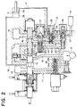
- an oil control valve 11 comprises a manual tilt spool 12 for operating a tilt cylinder 2 for tilting masts 1 of a fork lift truck.
- the tilt spool 12 is of a three-position type and is normally held at a neutral position as shown in the figure, and hydraulic oil sent from a hydraulic pump 13 through a supply passage 15 is constructed so as to return to a tank 14 through a return passage 16.
- the tilt spool 12 is connected to a rod side oil chamber 2a and a bottom side oil chamber 2b of the tilt cylinder 2 via passages 17, 18, respectively.
- a pilot operation type flow rate control valve 21 which is a two-position valve that can be switched between a fully opened position and a half opened position.
- the flow rate control valve 21 comprises a spool 22 having two large and small passages having different flow path cross-sectional areas, which are a full open passage 22a and a half open passage 22b.
- the spool 22 is normally held at the half opened position with a spring 22c where the half open passage 22b communicates with the rod side passage 17. Then, when a pilot pressure is applied to a pilot compartment 22d through a first pilot passage 23 connected to the supply passage 15, the spool 22 is switched to the fully opened position where the full open passage 22a communicates with the rod side passage 17.
- An electromagnetic switching valve 24 is provided on the first pilot passage 23.
- This electromagnetic switching valve 24 is of a normally opened type and is constructed such that when it is in an off state, the electromagnetic switching valve 24 is held by a spring 24b at a position where the spool 24a establishes a communication between the pilot passage 23 and the hydraulic pump 13, while when a solenoid 24c is excited (turned ON), the electromagnetic switching valve 24 is switched to a position where the spool 24a establishes a communication between the pilot passage 23 and the tank 14.
- a logic valve 31 is provided on the rod side passage 17 between the flow rate control valve 21 and the tilt cylinder 2.
- This logic valve 31 permits the flow of hydraulic oil into the rod side oil chamber 2a and comprises a poppet valve 32 which is controlled to be opened and/or closed by the presence of pilot pressure when the hydraulic oil flows out and a changeover valve 39 for controlling the presence of action of pilot pressure.
- the poppet valve 32 comprises a poppet 33 for opening and closing the flow passage, and in a valve opening direction the flowing out oil acts on a stepped pressure receiving surface 33a formed on the outer circumference of the poppet 33 through an orifice 35, while in a valve closing direction a spring force of a spring 38 acts on the poppet 33 and the pilot pressure from the flowing out oil is applied to a pilot compartment 34 through a pilot passage 36 (refer to Fig. 3).
- the changeover valve 39 provided on the pilot passage 36, the pilot passage 36 is connected with/isolated from a relief passage 37 communicating with the tank 14.
- the changeover valve 39 has a spool 39b which is normally held by a spring 39a at a position where the pilot passage 36 is isolated from the relief passage 37 and, at the same time, is connected with the rod side passage 17, and the spool 39b is switched to a position where the pilot passage 36 is connected with the relief passage 37 when the pilot pressure is applied to a pilot compartment 39c through a second pilot passage 40 branched off from the first pilot passage 23.
- the tilt control device according to the present invention is constructed as described above, and operation and effect thereof will be described below.
- the first pilot passage 23 then communicates with the tank 14, and since the pilot pressure in the pilot compartment 22d of the flow rate control valve 21 is deleted, the spool 22 of the flow rate control valve 21 is switched to the half opened position.
- the tilt cylinder 2 is tilted rearward at a speed slower than its normal speed.
- the logic valve 31 is closed to thereby prevent hydraulic oil from flowing out of the rod side oil chamber 2a, the forward tilting movement of the masts 1 being thereby prevented.
- the present invention by switching on or off the electromagnetic switching valve 24 or switching the same to the position where pilot pressure is added or to the position where the pilot pressure is deleted, when the masts are tilted rearward, the rearward tilting speed of the masts can be changed in two steps; high and low, and on the contrary, when the masts are tilted forward, switching can be effected between the state in which the masts can be tilted forward and the (stop) state in which the masts cannot be tilted forward.
- the rearward tilting speed control for the masts 1 can be effected in which the rearward tilting speed is made slower under the high lift height and heavy loaded condition than under the normal state by setting it such that the electromagnetic switching valve 24 is switched on in response to detection signals indicating, respectively, the mast rearward tilting, high lift height and heavily loaded condition in which a fork 3 is loaded.
- the forward tilting angle control for the masts 1 can be effected under the high lift height and heavy loaded condition by setting it such that the electromagnetic switching valve 24 is switched on in response to detection signals indicating, respectively, the mast forward tilting, high lift height and heavily loaded condition in which a fork 3 is loaded, and additionally in response to a detection signal indicating that the tilt angle of the mast reaches the predetermined value.
- an automatic horizontal feeding control of the fork also can be effected by detecting suitably that the fork 3 reaches the horizontal position with a detector and setting the electromagnetic switching valve 24 such that the valve is switched on in response to what is detected by the detector.
- the tilt control technique for a fork lift truck which can simplify the construction and reduce cost while securing the forward tilting angle control function and the rearward tilting speed control function for the masts which are equivalent in quality to those provided by the conventional technique.
- a tilt control device for a fork lift truck comprises a tilt spool for operating the tilt cylinder, a pilot operation type flow rate control valve connected to the hydraulic pump via the tilt spool and adapted to be switched between a fully opened position and a half opened position which are different in opening from each other in response to addition/deletion of a pilot pressure, a pilot operation type logic valve disposed between the rod side oil compartment of the tilt cylinder and the flow rate control valve and adapted to permit hydraulic oil to flow into the rod side oil compartment and to be operated so as to open/close relative to hydraulic oil flowing out of the rod side oil compartment in response to the addition/deletion of the pilot pressure, and an electromagnetic switching valve for controlling the addition/deletion of the pilot pressure to the flow rate control valve and the logic valve.
Landscapes
- Engineering & Computer Science (AREA)
- Transportation (AREA)
- Structural Engineering (AREA)
- Chemical & Material Sciences (AREA)
- Combustion & Propulsion (AREA)
- Civil Engineering (AREA)
- Life Sciences & Earth Sciences (AREA)
- Geology (AREA)
- Mechanical Engineering (AREA)
- Forklifts And Lifting Vehicles (AREA)
- Fluid-Pressure Circuits (AREA)
Abstract
Description
Claims (5)
- A tilt control device for a fork lift truck for allowing hydraulic oil received in a tank to flow into one of a rod side oil compartment and a bottom side oil compartments of a tilt cylinder using a hydraulic pump for tilting masts of the fork lift truck, said control device comprising;a tilt spool for operating said tilt cylinder,a pilot operation type flow rate control valve connected to said hydraulic pump via said tilt spool and adapted to be switched between a fully opened position and a half opened position which are different in opening from each other in response to addition/deletion of a pilot pressure,a pilot operation type logic valve disposed between said rod side oil compartment of said tilt cylinder and said flow rate control valve and adapted to permit hydraulic oil to flow into said rod side oil compartment and to be operated so as to open/close relative to hydraulic oil flowing out of said rod side oil compartment in response to the addition/deletion of the pilot pressure, andan electromagnetic switching valve for controlling the addition/deletion of the pilot pressure to said flow rate control valve and said logic valve.
- A tilt control device according to Claim 1, wherein said logic valve comprises;a poppet valve disposed between said rod side oil chamber of said tilt cylinder and said flow rate control valve, anda pilot operation type changeover valve for controlling the addition/deletion of the pilot pressure to said poppet valve for opening/closing thereof.
- A tilt control device according to Claim 2, wherein said electromagnetic valve adds the pressure of hydraulic oil sent from said hydraulic pump as the pilot pressure to said flow rate control valve and said changeover valve.
- A tilt control device according to Claim 2, wherein said changeover valve establishes/cuts off the communication between a pilot passage for guiding the pilot pressure to said poppet valve for opening/closing thereof and said tank.
- A tilt control device according to Claim 1, wherein said bottom side oil compartment of said tilt cylinder is connected to said hydraulic oil pump and said tank via said tilt spool.
Applications Claiming Priority (2)
| Application Number | Priority Date | Filing Date | Title |
|---|---|---|---|
| JP19202999 | 1999-07-06 | ||
| JP19202999A JP4208352B2 (en) | 1999-07-06 | 1999-07-06 | Forklift tilt control device |
Publications (3)
| Publication Number | Publication Date |
|---|---|
| EP1067087A2 true EP1067087A2 (en) | 2001-01-10 |
| EP1067087A3 EP1067087A3 (en) | 2004-07-21 |
| EP1067087B1 EP1067087B1 (en) | 2005-10-26 |
Family
ID=16284422
Family Applications (1)
| Application Number | Title | Priority Date | Filing Date |
|---|---|---|---|
| EP00114420A Expired - Lifetime EP1067087B1 (en) | 1999-07-06 | 2000-07-05 | Tilt control device for fork lift truck |
Country Status (4)
| Country | Link |
|---|---|
| US (1) | US6439102B1 (en) |
| EP (1) | EP1067087B1 (en) |
| JP (1) | JP4208352B2 (en) |
| DE (1) | DE60023400T2 (en) |
Cited By (4)
| Publication number | Priority date | Publication date | Assignee | Title |
|---|---|---|---|---|
| CN104019072A (en) * | 2014-06-11 | 2014-09-03 | 山重建机有限公司 | Pilot type multiway valve system and hydraulic system |
| CN109578391A (en) * | 2018-11-30 | 2019-04-05 | 武汉船用机械有限责任公司 | A kind of electric-hydraulic proportion integrated manipulator and its control method |
| EP3718957A1 (en) * | 2019-04-04 | 2020-10-07 | Kabushiki Kaisha Toyota Jidoshokki | Hydraulic drive apparatus for industrial vehicle |
| CN111762725A (en) * | 2020-07-20 | 2020-10-13 | 刘剑 | Fork control device of side forklift |
Families Citing this family (9)
| Publication number | Priority date | Publication date | Assignee | Title |
|---|---|---|---|---|
| US20050102081A1 (en) * | 2003-09-23 | 2005-05-12 | Patterson Mark A. | Lift truck active load stabilizer |
| US7344000B2 (en) * | 2004-09-23 | 2008-03-18 | Crown Equipment Corporation | Electronically controlled valve for a materials handling vehicle |
| JP4441386B2 (en) * | 2004-11-08 | 2010-03-31 | 株式会社豊田自動織機 | Flow switching type flow divider |
| US20080257651A1 (en) * | 2007-04-23 | 2008-10-23 | Williamson Joel L | Lift truck with productivity enhancing package including variable tilt and vertical masting |
| US7942711B1 (en) | 2008-01-09 | 2011-05-17 | Brunswick Corporation | Method for controlling a marine propulsion trim system |
| BR112013020758A2 (en) | 2011-02-16 | 2016-10-18 | Crown Equip Corp | material handling vehicle |
| US8863509B2 (en) * | 2011-08-31 | 2014-10-21 | Caterpillar Inc. | Meterless hydraulic system having load-holding bypass |
| CN104033450B (en) * | 2014-05-28 | 2016-05-25 | 广西柳工机械股份有限公司 | Hydraulic control unloader valve |
| CN109973455B (en) * | 2019-03-20 | 2020-08-04 | 中煤科工集团重庆研究院有限公司 | A Multi-stage Mixed-connected Accurate Speed Regulating Hydraulic System |
Family Cites Families (7)
| Publication number | Priority date | Publication date | Assignee | Title |
|---|---|---|---|---|
| JPS5633399A (en) * | 1979-08-20 | 1981-04-03 | Komatsu Forklift | Cargo work car |
| US4459081A (en) * | 1982-03-08 | 1984-07-10 | Cameron Iron Works, Inc. | Speed reducing mast tilt indicator |
| JPH10265194A (en) | 1997-03-24 | 1998-10-06 | Toyota Autom Loom Works Ltd | Hydraulic controller of industrial vehicle |
| DE69824066T2 (en) * | 1997-03-21 | 2005-05-25 | Kabushiki Kaisha Toyota Jidoshokki, Kariya | Hydraulic control unit for industrial trucks |
| JP3713877B2 (en) * | 1997-03-31 | 2005-11-09 | 株式会社豊田自動織機 | Tilt cylinder speed controller |
| JPH10330096A (en) | 1997-06-02 | 1998-12-15 | Toyota Autom Loom Works Ltd | Tilt control device of forklift truck |
| JPH11171494A (en) * | 1997-12-11 | 1999-06-29 | Toyota Autom Loom Works Ltd | Cylinder controller of industrial vehicle |
-
1999
- 1999-07-06 JP JP19202999A patent/JP4208352B2/en not_active Expired - Lifetime
-
2000
- 2000-07-05 DE DE60023400T patent/DE60023400T2/en not_active Expired - Lifetime
- 2000-07-05 EP EP00114420A patent/EP1067087B1/en not_active Expired - Lifetime
- 2000-07-06 US US09/610,792 patent/US6439102B1/en not_active Expired - Lifetime
Cited By (7)
| Publication number | Priority date | Publication date | Assignee | Title |
|---|---|---|---|---|
| CN104019072A (en) * | 2014-06-11 | 2014-09-03 | 山重建机有限公司 | Pilot type multiway valve system and hydraulic system |
| CN109578391A (en) * | 2018-11-30 | 2019-04-05 | 武汉船用机械有限责任公司 | A kind of electric-hydraulic proportion integrated manipulator and its control method |
| EP3718957A1 (en) * | 2019-04-04 | 2020-10-07 | Kabushiki Kaisha Toyota Jidoshokki | Hydraulic drive apparatus for industrial vehicle |
| CN111795022A (en) * | 2019-04-04 | 2020-10-20 | 株式会社丰田自动织机 | Hydraulic drive device for industrial vehicle |
| AU2020201867B2 (en) * | 2019-04-04 | 2021-08-12 | Kabushiki Kaisha Toyota Jidoshokki | Hydraulic drive apparatus for industrial vehicle |
| CN111795022B (en) * | 2019-04-04 | 2022-11-22 | 株式会社丰田自动织机 | Hydraulic drive device for industrial vehicle |
| CN111762725A (en) * | 2020-07-20 | 2020-10-13 | 刘剑 | Fork control device of side forklift |
Also Published As
| Publication number | Publication date |
|---|---|
| DE60023400T2 (en) | 2006-07-27 |
| JP4208352B2 (en) | 2009-01-14 |
| JP2001019391A (en) | 2001-01-23 |
| EP1067087A3 (en) | 2004-07-21 |
| EP1067087B1 (en) | 2005-10-26 |
| DE60023400D1 (en) | 2005-12-01 |
| US6439102B1 (en) | 2002-08-27 |
Similar Documents
| Publication | Publication Date | Title |
|---|---|---|
| EP1067087B1 (en) | Tilt control device for fork lift truck | |
| US5197283A (en) | Hydraulic-motor drive circuit system with anti-cavitation control | |
| EP0878440B1 (en) | Tilt control device for forklift | |
| JP3119722B2 (en) | Hydraulic circuit of 4-position closed center switching valve by pressure proportional control valve | |
| JPH10219730A (en) | Automatic horizontal-control hydraulic-power device | |
| US6125970A (en) | Hydraulic device for forklift | |
| EP0708252B1 (en) | Control valve with variable priority function | |
| US6314997B1 (en) | Multiple valve apparatus | |
| US4938022A (en) | Flow control system for hydraulic motors | |
| EP1070853B1 (en) | Cylinder control device | |
| US5201176A (en) | Hydraulic control circuit and hydraulic control apparatus therefor | |
| JP3713877B2 (en) | Tilt cylinder speed controller | |
| JPH05229792A (en) | Hydraulic controller for tilt cylinder in forklift | |
| EP0684388B1 (en) | Load-sensing active hydraulic control device | |
| JPH09165792A (en) | Control circuit for hydraulic power shovel | |
| JPH05288203A (en) | Pressure relieving device in oil hydraulic circuit having pressure compensating valve | |
| JP4455959B2 (en) | Hydraulic system | |
| JP2681841B2 (en) | Control device for variable displacement pump | |
| JPH10265194A (en) | Hydraulic controller of industrial vehicle | |
| JP3712312B2 (en) | Hydraulic control device | |
| JP2006071051A (en) | Directional control valve | |
| JP3742729B2 (en) | Hydraulic control device | |
| JPH068649Y2 (en) | Hydraulic control mechanism for lifting work equipment | |
| JPH0640322Y2 (en) | Liquid control device | |
| JPH0988901A (en) | Pump tilt angle control device |
Legal Events
| Date | Code | Title | Description |
|---|---|---|---|
| PUAI | Public reference made under article 153(3) epc to a published international application that has entered the european phase |
Free format text: ORIGINAL CODE: 0009012 |
|
| 17P | Request for examination filed |
Effective date: 20000705 |
|
| AK | Designated contracting states |
Kind code of ref document: A2 Designated state(s): AT BE CH CY DE DK ES FI FR GB GR IE IT LI LU MC NL PT SE |
|
| AX | Request for extension of the european patent |
Free format text: AL;LT;LV;MK;RO;SI |
|
| RAP1 | Party data changed (applicant data changed or rights of an application transferred) |
Owner name: KABUSHIKI KAISHA TOYOTA JIDOSHOKKI Owner name: NISHINA INDUSTRIAL CO., LTD. |
|
| PUAL | Search report despatched |
Free format text: ORIGINAL CODE: 0009013 |
|
| AK | Designated contracting states |
Kind code of ref document: A3 Designated state(s): AT BE CH CY DE DK ES FI FR GB GR IE IT LI LU MC NL PT SE |
|
| AX | Request for extension of the european patent |
Extension state: AL LT LV MK RO SI |
|
| GRAP | Despatch of communication of intention to grant a patent |
Free format text: ORIGINAL CODE: EPIDOSNIGR1 |
|
| AKX | Designation fees paid |
Designated state(s): DE FR GB |
|
| GRAS | Grant fee paid |
Free format text: ORIGINAL CODE: EPIDOSNIGR3 |
|
| GRAA | (expected) grant |
Free format text: ORIGINAL CODE: 0009210 |
|
| AK | Designated contracting states |
Kind code of ref document: B1 Designated state(s): DE FR GB |
|
| REG | Reference to a national code |
Ref country code: GB Ref legal event code: FG4D |
|
| REF | Corresponds to: |
Ref document number: 60023400 Country of ref document: DE Date of ref document: 20051201 Kind code of ref document: P |
|
| ET | Fr: translation filed | ||
| PLBE | No opposition filed within time limit |
Free format text: ORIGINAL CODE: 0009261 |
|
| STAA | Information on the status of an ep patent application or granted ep patent |
Free format text: STATUS: NO OPPOSITION FILED WITHIN TIME LIMIT |
|
| 26N | No opposition filed |
Effective date: 20060727 |
|
| REG | Reference to a national code |
Ref country code: FR Ref legal event code: PLFP Year of fee payment: 17 |
|
| REG | Reference to a national code |
Ref country code: FR Ref legal event code: PLFP Year of fee payment: 18 |
|
| REG | Reference to a national code |
Ref country code: FR Ref legal event code: PLFP Year of fee payment: 19 |
|
| PGFP | Annual fee paid to national office [announced via postgrant information from national office to epo] |
Ref country code: FR Payment date: 20190619 Year of fee payment: 20 |
|
| PGFP | Annual fee paid to national office [announced via postgrant information from national office to epo] |
Ref country code: DE Payment date: 20190625 Year of fee payment: 20 |
|
| PGFP | Annual fee paid to national office [announced via postgrant information from national office to epo] |
Ref country code: GB Payment date: 20190703 Year of fee payment: 20 |
|
| REG | Reference to a national code |
Ref country code: DE Ref legal event code: R071 Ref document number: 60023400 Country of ref document: DE |
|
| REG | Reference to a national code |
Ref country code: GB Ref legal event code: PE20 Expiry date: 20200704 |
|
| PG25 | Lapsed in a contracting state [announced via postgrant information from national office to epo] |
Ref country code: GB Free format text: LAPSE BECAUSE OF EXPIRATION OF PROTECTION Effective date: 20200704 |