EP1067077A2 - Method and device for sheet collation - Google Patents
Method and device for sheet collation Download PDFInfo
- Publication number
- EP1067077A2 EP1067077A2 EP00110153A EP00110153A EP1067077A2 EP 1067077 A2 EP1067077 A2 EP 1067077A2 EP 00110153 A EP00110153 A EP 00110153A EP 00110153 A EP00110153 A EP 00110153A EP 1067077 A2 EP1067077 A2 EP 1067077A2
- Authority
- EP
- European Patent Office
- Prior art keywords
- sheets
- sheet
- path
- paths
- collation
- Prior art date
- Legal status (The legal status is an assumption and is not a legal conclusion. Google has not performed a legal analysis and makes no representation as to the accuracy of the status listed.)
- Granted
Links
Images





Classifications
-
- B—PERFORMING OPERATIONS; TRANSPORTING
- B65—CONVEYING; PACKING; STORING; HANDLING THIN OR FILAMENTARY MATERIAL
- B65H—HANDLING THIN OR FILAMENTARY MATERIAL, e.g. SHEETS, WEBS, CABLES
- B65H29/00—Delivering or advancing articles from machines; Advancing articles to or into piles
- B65H29/58—Article switches or diverters
- B65H29/60—Article switches or diverters diverting the stream into alternative paths
-
- B—PERFORMING OPERATIONS; TRANSPORTING
- B65—CONVEYING; PACKING; STORING; HANDLING THIN OR FILAMENTARY MATERIAL
- B65H—HANDLING THIN OR FILAMENTARY MATERIAL, e.g. SHEETS, WEBS, CABLES
- B65H39/00—Associating, collating, or gathering articles or webs
- B65H39/10—Associating articles from a single source, to form, e.g. a writing-pad
-
- B—PERFORMING OPERATIONS; TRANSPORTING
- B65—CONVEYING; PACKING; STORING; HANDLING THIN OR FILAMENTARY MATERIAL
- B65H—HANDLING THIN OR FILAMENTARY MATERIAL, e.g. SHEETS, WEBS, CABLES
- B65H2513/00—Dynamic entities; Timing aspects
- B65H2513/40—Movement
- B65H2513/42—Route, path
Definitions
- the present invention relates generally to an inserting machine for mass mailing and, more specifically, a method and device to cause a large number of separate cut sheets to be collated into individual stacks each having a number of sheets.
- Multi-station document inserting systems are generally used by organizations such as banks, insurance companies and utility companies for producing a large volume of specific mailings where the contents of each mailpiece are directed to a particular addressee.
- One of the most important features of the inserting systems is speed, which is measured by the number of mailpieces that can be assembled in a given time period.
- a modern inserting system is expected to assemble over ten thousand mailpieces per hour.
- a typical inserter system includes a plurality of serially arranged stations including a sheet feeding station, a folding station and an insertion station.
- the sheet feeder feeds one or a plurality of sheets of mailing materials to a collator, which collects the fed sheets into a predefined collated packet or stack.
- Mailing materials are usually printed on a continuous web of paper and the printed paper is cut into individual sheets. These sheets are then collated into individual stacks and each stack is stuffed into art envelope for mailing.
- One of the conventional ways of sheet collation is to slow down or stop the sheets in an impending collation at a certain point until all the sheets have arrived. This conventional method is cumbersome and inefficient because it requires a drastic change in machine speed.
- the sheet collation method provides a plurality of paths connecting the entry point and the exiting point, with each path having a different path length. The paths are controlled so that, for each stack of the sheets in an impending collation, a sheet entering the collator will travel a progressively shorter path than the preceding one. In other words, the first sheet travels a longer path than the second sheet, the second sheet travels a longer path than the third sheet, and so forth.
- the path length difference between two successive paths can be designed in accordance with the requirement in sheet stacking. If the sheets are stacked in a way that one sheet is partially overlapped with another, like the shingle pattern on a rooftop, then the path length difference between two successive paths is smaller than the length of the sheets. If the edges of the collated sheets in a stack are flush with each other, then the path length difference is substantially equal to the sheet length. But the path length difference can also be greater than the sheet length.
- cut sheets of paper enter the collator in a serial fashion, usually from a cutting device upstream that has converted a continuous web of paper into individual sheets.
- the sheets are gathered or collated into individual stacks before they are stuffed into envelopes.
- the number of provided paths in a collator is fixed, but the number of sheets in each stack can be varied.
- the collator includes means for determining the number of sheets in an impending collation.
- the number of provided paths is five and the number of sheets in a stack is three, then only the three shorter paths should be successively opened for sheet collation, with the shortest path being traveled by the third sheet. If the number of sheets in a stack in an impending collation is greater than five, then two or more smaller stacks can be collated in the collator and later combined at a point downstream of the collator.
- One of the major advantages of the method and device for sheet collation, according to the present invention, is that all the sheets entering and exiting the device can be of the same speed. Furthermore, the collated sheets can be moved at the same or a higher speed, if so desired. Thus, the processing speed downstream of the collator is not impeded by the collation process.
- the sheet collator includes a plurality of turn-bars for defining the traveling paths, a plurality of flippers to control the opening and closing of the paths so that, for each stack in the impending collation, a sheet entering the entry point will travels a shorter path than the preceding one.
- Each flipper is connected to a push rod which is controlled by a solenoid.
- the collator further comprises rollers and belts for guiding the sheets through different paths to exit at the exiting point of the collator.
- the paths are defined by rollers.
- the opening and closing of the paths are controlled by flippers.
- Fig. 1 illustrates the function of a sheet collator.
- reference numeral 10 denotes a sheet collator
- S1 , S2 and S3 denote three cut sheets separately and serially entering an entry point 12 .
- the sheets exit the exiting point 14 they are stacked up in a stack ST such that S3 is positioned on top of S2 , which, in turn, is positioned on top of S1 .
- the overlapping of a sheet on top of another can be partial as shown, like shingles on a rooftop. But the sheets can also be stacked up such that the edge of each sheet aligns evenly with the edges of the other sheets.
- Fig. 2 illustrates the principle of sheet collation, according to the present invention.
- the first three paths are denoted by P1 , P2 and P3 , with the path length of path P1 being shorter than P2 , P2 being shorter than P3 , and so on.
- a controlling means for opening and closing the path so that only one sheet in a stack in an impending collation is allowed to travel through the path. For example, in collating three sheets, the first sheet entering the entry point 12 will be caused to travel path P3 by keeping C1 and C2 in the closing position while C3 is in the opening position, as shown in Fig. 2.
- the next entering sheet will be caused to travel path P2 by keeping C1 in the closing position and C2 in the opening position. It is followed that C1 is kept in the opening position to allow the last sheet to travel along path P1 .
- the path length difference between two adjacent paths shown in Fig. 2 is given by 2Y . If the length of the sheets is L , then the path length difference 2Y should be smaller than L so that the sheets are only partially overlapped with each other. But 2Y can also be equal to the sheet length L so as to allow the sheets in the impending collation to exit the collator concurrently. Moreover, it is also plausible that 2Y is greater than the sheet length L .
- the collator includes a sensing device 13 to determine the number of sheets in an impending collation.
- the sensing device can be located behind or in front of the entry point 12 .
- Fig. 3 illustrates the preferred collation method of the present invention.
- a sheet collator 10 includes a number of turn-bars 20 which are positioned one above another, leaving gaps therebetween to define traveling paths.
- Shown in Fig. 3 are three traveling paths P1 , P2 and P3 , each of which is associated with a flipper 30 for opening or closing the path.
- the flippers associated with path P1 and path P2 are in the closing position so as to block the sheet from entering either path.
- the flipper associated with path P3 is in the opening position to allow a sheet entering the entry point 12 to travel along path P3 to reach the exiting point 14 .
- the path traveled by that particular sheet is denoted by a dashed line.
- the sheet collator also includes power driven rollers 18 and 38 , belts 22 and 34 , a number of other rollers 24 , 26 and 32 to guide the sheets through the collator. It should be noted that the gaps between the turn-bars and the belts are greatly exaggerated to show the traveling paths.
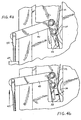
- Fig. 4a and Fig. 4b show the preferred mechanism for controlling the flipper 30 associated with each path.
- the opening and closing of flipper 30 is caused by the action of a push rod 42 which is linked to the flipper by a lever 40 .
- flipper 30 is in a closing position, blocking a sheet from passing through the path associated with the flipper.
- push rod 42 is shown to be pushed upward to cause flipper 30 to move inward, allowing a sheet to pass through the path.
- the movement of push rod 42 is caused by a pneumatic solenoid 44 , an electrical solenoid, an electric rotary actuator or another actuator type mechanism.
- Fig. 5 illustrates a cross sectional view of the collator, according to the preferred embodiment of the present invention.
- a group of five turn-bars 20 being positioned one atop another to define five different paths, P1 to P5 .
- the longest path, or P5 is defined by the lowest turn-bar and a terminating bar 46 .
- Each of the top four turn-bars has a flipper 30 to open or close the path associated with the turn-bar.
- the collator also preferably includes a number of optical sensors, each to a turn-bar to sense the passage of the sheets.
- Fig. 5 Only two optical sensors are shown in Fig. 5, denoted by reference numeral 48 . It is to be appreciated that the collator depicted in Fig. 5 is to be understood as a preferred embodiment of the present invention and hence it is not to be understood to be limited to only five travel paths (P1-P5), but rather may encompass any commercially practicable number of travel, whether greater or less than five.
- Fig. 6 illustrates another view of the collator, according to the preferred embodiment of the present invention.
- the collator has two pivotable wings 50 and 52 for installing guiding rollers and belts.
- the wings can be opened and separated from the turn-bars 30 .
- wing 50 is properly closed, a plurality of rollers 24 will push the belt 22 against each of the turn-bars 30 to create a paper path substantially conforming to the surface of the turn-bar as shown.
- a flipper 30 is caused to move inward to open a path, a sheet encountering an opened path will be guided through the path under the turn-bar. Otherwise the sheet will travel to the next turn-bar.
- wing 52 As wing 52 is in the opening position, the mechanism that controls the flippers 30 can be seen. As shown in Fig. 6, a number of solenoids 44 , push rods 42 and levers 40 are used to control the movement of flippers 30 .
- reference numeral 54 denotes a plurality of connectors to the optical sensors 48 shown in Fig. 5.
- Reference numeral 56 denotes a plurality of holding shafts which are part of the wing construction.
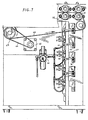
- Fig. 7 illustrates another view of the preferred embodiment, showing the pneumatic manifold connecting solenoids 44 to a pneumatic controller unit 60 . Also shown in Fig. 7 are a motor 62 , a pulley system 64 and driving belts 66 , 68 to drive rollers 18 and 38 . With rollers 18 and 38 being driven by the same motor, sheets enter and exit the collator at the same speed. However, it is preferred that roller 38 run slightly faster than roller 18 to increase the operational efficiency. Moreover, solenoids 44 can be replaced by electric rotary actuators to control the flippers.
- Fig. 8 illustrates another embodiment of the present invention.
- the collating device in Fig. 8 is constructed as a vertical "tower" to achieve a small footprint.
- a plurality of rollers 70 and 72 are used to guide a plurality of cut sheets, serially and separately entering an entry point 12 , to move through different paths P1 , P2 , P3 , ... and to exit at an exiting point 14 .
- the opening and closing of the paths are controlled by flippers F1 , F2 , F3 , ... If flipper F1 is in an opening position, a sheet entering the entry point will travel along path P1 to the exiting point.
- the path length difference between two adjacent paths is determined by the spacings Y1 , Y2 between rollers, and the radius R of rollers 70 as shown. It is understood that while it is shown in Fig. 8 that all rollers 70 are of the same size, it is not necessarily so.
Landscapes
- Engineering & Computer Science (AREA)
- Mechanical Engineering (AREA)
- Collation Of Sheets And Webs (AREA)
Abstract
Description
Claims (22)
- A method of collating a plurality of sheets of flat material wherein the sheets enter in seriatim at an entry point and become at least partially overlapped with each other in an orderly fashion at an exiting point, said method comprising the steps of:a) providing a plurality of paths connecting the entry point and the exiting point, each path having a different path length; andb) controlling said paths so as to allow each sheet of a collation to travel a different path such that a sheet succeeding a preceding sheet of a collation entering the entry point travels a different length path than the preceding sheet.
- The method of claim 1, wherein the succeeding sheet of a collation travels a shorter path length than each preceding sheet of the collation.
- The method of claim 1 wherein each of said sheets of a collation has an approximately equal sheet length, wherein the difference between the paths traveled by two successively entering sheets is less than the sheet length.
- The method of claim 1 wherein each of said sheets of a collation has an approximately equal sheet length, wherein the difference between the paths traveled by two successively entering sheets is substantially equal to the sheet length.
- The method of claim 1 wherein each of said sheets of a collation has an approximately equal sheet length, wherein the difference between the paths traveled by two successively entering sheets is greater than the sheet length.
- A method of collating a multiplicity of cut sheets into a plurality of stacks, said cut sheets entering in seriatim at an entry point, each stack having a number of said cut sheets at least partially overlaid one upon another in an orderly fashion at an exiting point, said method comprising the steps of:1) providing a plurality of paths connecting the entry point and the exiting point, each path having a different path length; and2) controlling said paths so as to allow each of the cut sheets to be collated in a stack to travel a shorter path than the preceding sheet.
- The method of claim 6 further comprising the step of determining the number of sheets in a stack in an impending collation.
- The method of claim 6 or 7 wherein the number of sheets in at least one stack is different from the number of sheets in other stacks.
- The method of claim 6 or 7 wherein the number of sheets in each stack is the same.
- A device for collating a plurality of sheets wherein the sheets enter in seriatim at an entry point and become at least partially overlapped with each other at an exiting point, comprising:a) a plurality of paths connecting the entry point and the exiting point, each path having a different path length; andb) a switching mechanism for controlling said paths so as to allow each sheet to travel a different path such that a sheet succeeding a preceding sheet of a collation entering the entry point travels a different length path than the preceding sheet.
- A device for collating a plurality of sheets as recited in claim 10, wherein the succeeding sheet of a collation travels a shorter path length than each preceding sheet of a collation.
- A device for collating a plurality of sheets as recited in claim 10 or 11, wherein each path has a substantially curved configuration.
- The device of any one of the claims 10 to 12, further including a plurality of turn-bars located between the entry point and the exiting point, said turn-bars being positioned one on top of another to define the paths.
- The device of any one of the claims 10 to 12, further including a plurality of first rollers located between the entry point and the exiting point, said first rollers being arranged in rows to define the paths.
- The device of claim 14 further including guiding belts and second rollers for guiding the sheets through the paths.
- The device of claim 15 further including drive rollers for moving said guiding belts.
- The device of claim 16 further comprising means for driving said drive rollers.
- The device of any one of the claims 10 to 17, wherein the switching mechanism includes flippers movable at least between two positions.
- The device of claim 18 wherein each of the flippers is controlled by a solenoid.
- The device of any one of the claims 10 to 19, further including sensors for sensing the passage of the sheets through each path.
- The device of any one of the claims 10 to 20, further comprising at least one wing which can be opened and separated from the paths for enabling access to each path to facilitate maintenance.
- An insertion machine comprising a device according to any one of the preceding claims 10 to 21.
Applications Claiming Priority (2)
| Application Number | Priority Date | Filing Date | Title |
|---|---|---|---|
| US310217 | 1981-10-09 | ||
| US09/310,217 US6273419B1 (en) | 1999-05-12 | 1999-05-12 | Method and device for sheet collation |
Publications (3)
| Publication Number | Publication Date |
|---|---|
| EP1067077A2 true EP1067077A2 (en) | 2001-01-10 |
| EP1067077A3 EP1067077A3 (en) | 2002-04-10 |
| EP1067077B1 EP1067077B1 (en) | 2004-09-15 |
Family
ID=23201488
Family Applications (1)
| Application Number | Title | Priority Date | Filing Date |
|---|---|---|---|
| EP00110153A Expired - Lifetime EP1067077B1 (en) | 1999-05-12 | 2000-05-12 | Method and device for sheet collation |
Country Status (4)
| Country | Link |
|---|---|
| US (1) | US6273419B1 (en) |
| EP (1) | EP1067077B1 (en) |
| CA (1) | CA2307825C (en) |
| DE (1) | DE60013706T2 (en) |
Cited By (1)
| Publication number | Priority date | Publication date | Assignee | Title |
|---|---|---|---|---|
| WO2013034703A1 (en) * | 2011-09-09 | 2013-03-14 | Böwe Systec Gmbh | Device and method for merging goods |
Families Citing this family (6)
| Publication number | Priority date | Publication date | Assignee | Title |
|---|---|---|---|---|
| DE19859535A1 (en) * | 1998-12-22 | 2000-06-29 | Giesecke & Devrient Gmbh | Device for turning sheet material |
| US6568676B2 (en) * | 2001-10-17 | 2003-05-27 | Pitney Bowes Inc. | Removable turnbar in a sheet accumulator |
| US20050017438A1 (en) * | 2003-06-30 | 2005-01-27 | Pitney Bowes Incorporated | Apparatus and method for accumulating sheets |
| US8061712B2 (en) | 2007-01-26 | 2011-11-22 | Canon Kabushiki Kaisha | Sheet conveying apparatus and image forming apparatus |
| US20100042252A1 (en) * | 2008-08-13 | 2010-02-18 | Xerox Corporation | Disk type apparatus and corresponding methods |
| JP5257223B2 (en) * | 2009-04-27 | 2013-08-07 | コニカミノルタビジネステクノロジーズ株式会社 | Post-processing apparatus, paper discharge method thereof, and image forming system |
Family Cites Families (15)
| Publication number | Priority date | Publication date | Assignee | Title |
|---|---|---|---|---|
| US4102253A (en) * | 1976-10-26 | 1978-07-25 | Gannicott David James H | Counting and stacking unit |
| US4190241A (en) | 1978-05-01 | 1980-02-26 | Kimberly-Clark Corporation | Apparatus for converting paper rolls into stacks of individual folded paper sheets |
| US4355795A (en) | 1980-03-04 | 1982-10-26 | Bobst Champlain, Inc. | Sheet handling device |
| US4585113A (en) | 1983-10-05 | 1986-04-29 | R. A. Jones & Co. Inc. | Apparatus for transferring articles |
| GB8505759D0 (en) | 1985-03-06 | 1985-04-11 | De La Rue Syst | Assembling sheets into stack |
| US4905044A (en) | 1986-11-19 | 1990-02-27 | Minolta Camera Kabushiki Kaisha | Document conveying apparatus |
| DE3723259C2 (en) * | 1987-07-14 | 1995-04-13 | Licentia Gmbh | Stacking device for letters |
| JPH0699070B2 (en) * | 1987-11-10 | 1994-12-07 | キヤノン株式会社 | Sheet handling equipment |
| US4989853A (en) | 1988-11-28 | 1991-02-05 | Xerox Corporation | Apparatus for offsetting sheets |
| US5018720A (en) * | 1990-03-22 | 1991-05-28 | Ncr Corporation | Document transport module |
| US5083769A (en) * | 1990-05-04 | 1992-01-28 | Pitney Bowes Inc. | Dual collating machine |
| US5255498A (en) * | 1990-11-02 | 1993-10-26 | Pitney Bowes Inc. | Envelope stuffing apparatus |
| JPH05286619A (en) * | 1992-04-07 | 1993-11-02 | Ricoh Co Ltd | Sheet discharge device of image forming device |
| US5258817A (en) | 1992-07-01 | 1993-11-02 | Xerox Corporation | Document handling system having a shunt path |
| US5445368A (en) * | 1993-10-27 | 1995-08-29 | Pitney Bowes Inc. | Apparatus and method for forming collations of two different size documents |
-
1999
- 1999-05-12 US US09/310,217 patent/US6273419B1/en not_active Expired - Fee Related
-
2000
- 2000-05-09 CA CA002307825A patent/CA2307825C/en not_active Expired - Fee Related
- 2000-05-12 DE DE60013706T patent/DE60013706T2/en not_active Expired - Lifetime
- 2000-05-12 EP EP00110153A patent/EP1067077B1/en not_active Expired - Lifetime
Cited By (1)
| Publication number | Priority date | Publication date | Assignee | Title |
|---|---|---|---|---|
| WO2013034703A1 (en) * | 2011-09-09 | 2013-03-14 | Böwe Systec Gmbh | Device and method for merging goods |
Also Published As
| Publication number | Publication date |
|---|---|
| CA2307825A1 (en) | 2000-11-12 |
| EP1067077B1 (en) | 2004-09-15 |
| DE60013706T2 (en) | 2005-09-22 |
| EP1067077A3 (en) | 2002-04-10 |
| US6273419B1 (en) | 2001-08-14 |
| DE60013706D1 (en) | 2004-10-21 |
| CA2307825C (en) | 2007-03-20 |
Similar Documents
| Publication | Publication Date | Title |
|---|---|---|
| US6161828A (en) | Sheet collation device and method | |
| US5514066A (en) | Buckle chute folding machine for different length sheets | |
| CA2041608A1 (en) | Dual collating machine | |
| US7021184B2 (en) | System and method for providing sheets to an inserter system using a rotary cutter | |
| EP1053963B1 (en) | A system and method for providing document accumulation sets to an inserter system | |
| CA2307825C (en) | Method and device for sheet collation | |
| US7628396B2 (en) | High speed shingled sheet compiler | |
| EP1108563B1 (en) | Method for supplying envelopes to an inserter system | |
| JPS63501148A (en) | Document guide mechanism | |
| EP1433732B1 (en) | Buffer transport system for an inserter system | |
| US8172090B1 (en) | Large and small document combination optimization for document sequencing system | |
| EP1795473B1 (en) | High throughput right angle turn module | |
| EP1577242A1 (en) | System and method for providing sheets to an inserter system using a high speed cutter and right angle turn | |
| US6568676B2 (en) | Removable turnbar in a sheet accumulator | |
| EP1493700B1 (en) | Apparatus and method for accumulating sheets | |
| EP1634840A1 (en) | Sheet accumulator systems | |
| US5685531A (en) | Process for accumulating unfolded paper sheets and collating with folded sheets | |
| US7591454B2 (en) | Paper handling system material feed path arrangement | |
| EP1634834A2 (en) | Speed control for sheet handling apparatus | |
| EP2279975B1 (en) | Paper handling apparatus and method for operating a paper handling apparatus | |
| US20060151941A1 (en) | Speed control for sheet handling apparatus | |
| US20080257799A1 (en) | Apparatus & method for high speed document collation for insert into newspaper and other printed media | |
| US7416184B2 (en) | Sheet buffer device with rotating disk | |
| EP1634835B1 (en) | Trailing edge deflector for sheet handling apparatus and corresponding method | |
| EP1785376A2 (en) | Accumulation system for processing media items of various sizes and types |
Legal Events
| Date | Code | Title | Description |
|---|---|---|---|
| PUAI | Public reference made under article 153(3) epc to a published international application that has entered the european phase |
Free format text: ORIGINAL CODE: 0009012 |
|
| AK | Designated contracting states |
Kind code of ref document: A2 Designated state(s): DE FR GB Kind code of ref document: A2 Designated state(s): AT BE CH CY DE DK ES FI FR GB GR IE IT LI LU MC NL PT SE |
|
| AX | Request for extension of the european patent |
Free format text: AL;LT;LV;MK;RO;SI |
|
| PUAL | Search report despatched |
Free format text: ORIGINAL CODE: 0009013 |
|
| AK | Designated contracting states |
Kind code of ref document: A3 Designated state(s): AT BE CH CY DE DK ES FI FR GB GR IE IT LI LU MC NL PT SE |
|
| AX | Request for extension of the european patent |
Free format text: AL;LT;LV;MK;RO;SI |
|
| 17P | Request for examination filed |
Effective date: 20021002 |
|
| AKX | Designation fees paid |
Free format text: DE FR GB |
|
| 17Q | First examination report despatched |
Effective date: 20030410 |
|
| GRAP | Despatch of communication of intention to grant a patent |
Free format text: ORIGINAL CODE: EPIDOSNIGR1 |
|
| GRAS | Grant fee paid |
Free format text: ORIGINAL CODE: EPIDOSNIGR3 |
|
| GRAA | (expected) grant |
Free format text: ORIGINAL CODE: 0009210 |
|
| AK | Designated contracting states |
Kind code of ref document: B1 Designated state(s): DE FR GB |
|
| REG | Reference to a national code |
Ref country code: GB Ref legal event code: FG4D |
|
| REG | Reference to a national code |
Ref country code: IE Ref legal event code: FG4D |
|
| REF | Corresponds to: |
Ref document number: 60013706 Country of ref document: DE Date of ref document: 20041021 Kind code of ref document: P |
|
| ET | Fr: translation filed | ||
| PLBE | No opposition filed within time limit |
Free format text: ORIGINAL CODE: 0009261 |
|
| STAA | Information on the status of an ep patent application or granted ep patent |
Free format text: STATUS: NO OPPOSITION FILED WITHIN TIME LIMIT |
|
| 26N | No opposition filed |
Effective date: 20050616 |
|
| PGFP | Annual fee paid to national office [announced via postgrant information from national office to epo] |
Ref country code: FR Payment date: 20110607 Year of fee payment: 12 |
|
| REG | Reference to a national code |
Ref country code: FR Ref legal event code: ST Effective date: 20130131 |
|
| PG25 | Lapsed in a contracting state [announced via postgrant information from national office to epo] |
Ref country code: FR Free format text: LAPSE BECAUSE OF NON-PAYMENT OF DUE FEES Effective date: 20120531 |
|
| PGFP | Annual fee paid to national office [announced via postgrant information from national office to epo] |
Ref country code: DE Payment date: 20160527 Year of fee payment: 17 Ref country code: GB Payment date: 20160527 Year of fee payment: 17 |
|
| REG | Reference to a national code |
Ref country code: DE Ref legal event code: R119 Ref document number: 60013706 Country of ref document: DE |
|
| GBPC | Gb: european patent ceased through non-payment of renewal fee |
Effective date: 20170512 |
|
| PG25 | Lapsed in a contracting state [announced via postgrant information from national office to epo] |
Ref country code: DE Free format text: LAPSE BECAUSE OF NON-PAYMENT OF DUE FEES Effective date: 20171201 Ref country code: GB Free format text: LAPSE BECAUSE OF NON-PAYMENT OF DUE FEES Effective date: 20170512 |