EP1067024A2 - Cable reel - Google Patents
Cable reel Download PDFInfo
- Publication number
- EP1067024A2 EP1067024A2 EP00305680A EP00305680A EP1067024A2 EP 1067024 A2 EP1067024 A2 EP 1067024A2 EP 00305680 A EP00305680 A EP 00305680A EP 00305680 A EP00305680 A EP 00305680A EP 1067024 A2 EP1067024 A2 EP 1067024A2
- Authority
- EP
- European Patent Office
- Prior art keywords
- cable
- peripheral wall
- fixed case
- opening
- connector
- Prior art date
- Legal status (The legal status is an assumption and is not a legal conclusion. Google has not performed a legal analysis and makes no representation as to the accuracy of the status listed.)
- Withdrawn
Links
- 230000002093 peripheral effect Effects 0.000 claims abstract description 67
- 238000003466 welding Methods 0.000 claims abstract description 16
- 239000004020 conductor Substances 0.000 claims abstract description 9
- 238000009413 insulation Methods 0.000 claims description 5
- 239000000853 adhesive Substances 0.000 claims description 3
- 230000001070 adhesive effect Effects 0.000 claims description 3
- 238000000034 method Methods 0.000 description 5
- 238000009434 installation Methods 0.000 description 2
- 239000000463 material Substances 0.000 description 2
- 238000010276 construction Methods 0.000 description 1
- 239000000428 dust Substances 0.000 description 1
- 230000008030 elimination Effects 0.000 description 1
- 238000003379 elimination reaction Methods 0.000 description 1
- 238000003780 insertion Methods 0.000 description 1
- 230000037431 insertion Effects 0.000 description 1
- 239000011347 resin Substances 0.000 description 1
- 229920005989 resin Polymers 0.000 description 1
Images


Classifications
-
- B—PERFORMING OPERATIONS; TRANSPORTING
- B60—VEHICLES IN GENERAL
- B60R—VEHICLES, VEHICLE FITTINGS, OR VEHICLE PARTS, NOT OTHERWISE PROVIDED FOR
- B60R16/00—Electric or fluid circuits specially adapted for vehicles and not otherwise provided for; Arrangement of elements of electric or fluid circuits specially adapted for vehicles and not otherwise provided for
- B60R16/02—Electric or fluid circuits specially adapted for vehicles and not otherwise provided for; Arrangement of elements of electric or fluid circuits specially adapted for vehicles and not otherwise provided for electric constitutive elements
- B60R16/023—Electric or fluid circuits specially adapted for vehicles and not otherwise provided for; Arrangement of elements of electric or fluid circuits specially adapted for vehicles and not otherwise provided for electric constitutive elements for transmission of signals between vehicle parts or subsystems
- B60R16/027—Electric or fluid circuits specially adapted for vehicles and not otherwise provided for; Arrangement of elements of electric or fluid circuits specially adapted for vehicles and not otherwise provided for electric constitutive elements for transmission of signals between vehicle parts or subsystems between relatively movable parts of the vehicle, e.g. between steering wheel and column
Definitions
- the present invention relates to a cable reel to be mounted on a steering device of an automobile.
- a fixed case which includes a protruding peripheral wall having an annular bottom wall.
- a rotor is rotatable within the inner periphery of the peripheral wall, and the rotor is provided with an annular upper wall.
- An annular cable housing is formed by interfitting the rotor in a rotatable manner with the fixed case, and a cable reel is mounted to house a flat cable in the annular cable housing in a spiral manner.
- a connector fixed on the internal end of the flat cable rotates with the flat cable in accordance with the rotation of the steering device which is fixed with the rotor, while a connector fixed on the external end of the flat cable is fixed on a fixed case which is fixed to the body of the automobile.
- a combination switch mounting member is mounted separately from the cable reel, which is connected with a connector mounted on a fixed case of cable reel.
- a combination switch fixing area may be integrally mounted on the fixed case of the cable reel.
- a connector housing 1b provides a combination switch mounting area on a peripheral wall 1a of a fixed case 1 having a bottom opening 1c.
- a flat cable 4 is inserted into the fixed case 1, and both terminals of the flat cable 4 are connected with connectors 2 and 3.
- the connector 2 is connected with the external end of flat cable 4 through the bottom opening 1c and then is inserted into a connector housing 1b.
- a case 5 having an annular bottom wall is interfitted and fixed within the bottom opening 1c of fixed case 1, and a movable rotor 6 is mounted in a rotatable manner in an upper opening of the fixed case 1.
- a rotor cover 7 is fixed to the rotor 6 after interfitting and fixing the connector 3, and a locking collar 8 is inserted in a rotatable manner into the bottom wall of case 5 and connected to the rotor 6.
- the number of components becomes greater, which causes such problems as increasing the number of assembling processes due to providing a bottom wall of case 5 and disposing the bottom wall of the fixed case 1 as a separate body.
- the bottom wall of case 5 is made continuous to a peripheral wall by forming the same unitarily with the fixed case 1, it is necessary to provide a notch in the peripheral wall.
- a notch is provided, the connecting area between the flat cable and the connector become exposed on the peripheral wall side, causing possible intrusion of foreign matter thereinto, which gives rise to poor appearance and problems of impairing the performance of the cable reel.
- the present invention was made in view of the aforementioned problems, and more particularly with the preferred objectives of reducing the number of components and the assembling processes by forming the bottom wall of the fixed case unitarily and in one piece with the fixed case, and of avoiding increasing the size of the fixed case by forming the opening for the cable in the peripheral wall of the fixed case.
- the present invention provides a cable reel which includes a fixed case having a peripheral wall that protrudes from an outer periphery of an annular bottom wall, a moveable case having a peripheral wall that protrudes from the inner periphery of an annular upper wall, the fixed case and the movable case being interfitted in a rotatable manner and forming an annular cable housing space.
- the fixed case and the movable case house a flat a flat cable spirally in the cable housing.
- An opening is formed in a portion of the peripheral wall of the fixed case, and the connector housing is provided with a combination switch fixing area formed unitarily and in one piece on the bottom wall at a lower end of the opening area.
- a connector is connected with the terminal of external cable by welding at a vertical lower end of a bus-bar by laying narrow-strip bus-bars in parallel on an insulation board with the exposed ends of the flat cable conductors welded to the ends in the horizontal direction of each bus-bar. Accordingly, the welding area of the flat cable and the bus-bar of the connector is positioned at the opening, the welding area of the bus-bar and the cable is interfitted into the connector housing, and the opening in the peripheral wall of the fixed case is covered with a cover such that a continuous peripheral wall is provided having the same curvature as the cover. The cover is fixed to the peripheral wall by one of a lock connection and thermal adhesive.
- a spirally-housed flat cable having both ends connected with connectors is inserted from an upper opening of a fixed case, a connector connected with an external peripheral end of flat cable is inserted downwardly in an opening provided on the peripheral wall of the fixed case and is interfitted with a connector housing protruding downwardly from the bottom wall.
- a flat cable is housed in the fixed case, an opening in the peripheral wall of the fixed case is closed by a cover, thus covering a welded area between the flat cable and a bus-bar.
- the bottom wall is formed unitarily and in one piece with the fixed case, a reduction in the number of components and assembling processes can be achieved compared with the situation where the bottom wall is provided as separate member.
- the opening of the peripheral wall is closed with a cover, and the cover does not protrude from the peripheral wall and is made to have a configuration that forms a part of the peripheral wall housing having the same curvature as that of the peripheral wall, the outer diameter of the cable reel does not increase.
- the connector housing is formed unitarily and in one piece with the combination switch fixing area that protrudes downwardly from the bottom wall, it is possible to unitarily connect the combination switch fixing area without increasing the outer diameter of the cable reel.
- a cable reel in another aspect of the invention, includes a fixed case having an annular bottom wall.
- the fixed case includes a peripheral wall that extends upwardly from an outer periphery of the annular bottom wall.
- a movable case is provided having an annular upper wall, and the movable case includes a peripheral wall that extends outwardly from the inner periphery of the annular upper wall.
- the fixed case and the movable case are configured to interfit in a rotatable manner and to form an annular cable housing space.
- a flat cable is spirally wound in the annular cable housing space, an opening is formed in a portion of the peripheral wall of the fixed case, and a connector housing is formed unitarily and in one piece with a combination switch fixing area on the bottom wall at a lower end of the opening area.
- the cable reel includes a connector connected to the terminals of an external portion of the cable at a vertical lower end of a bus-bar.
- the connector may be connected to the terminals of the external portion of the portion of the cable by welding, and the welding may further include laying narrow-strip bus-bars in parallel on an insulation board with exposed ends of flat cable conductors welded to ends of each bus-bar in a horizontal direction. Additionally, the welding area of the flat cable and the bus-bar of the connector may be positioned at the opening, and the welding area of the bus-bar and the cable may be interfitted into the connector housing.
- the opening in the peripheral wall of the fixed case may be provided with a cover, such that a continuous peripheral wall is provided, and the cover may be provided to have a same curvature as the peripheral wall of the fixed case. Additionally, the cover may be fixed to the peripheral wall by one of a locking connection and thermal adhesive.
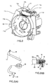
- Fig. 1 shows a cable reel 10 constructed by mounting a movable case 12 onto a fixed case 11, as shown in detail in Fig. 2.
- the fixed case 11 is molded from a suitable resin material, and includes a cylindrical peripheral wall 11b that protrudes upwardly from the external periphery of an annular bottom wall 11a.
- a combination switch is mounted in such a manner that a combination switch fixing area 11c protrudes outwardly from the annular outer peripheral end of the bottom wall 11a, and a combination switch mounting frame area 11d extends rearwardly from the combination switch fixing area 11c.
- An opening 13 is provided on a portion of the peripheral wall 11b to extend from the outer end of the opening to the lower end at the bottom wall.
- a connector housing 11f which is formed continuous with the bottom wall 11a, protrudes rearwardly at the lower end of the opening 13.
- the connector housing 11f has a housing space 11g which interfits with a connector 15 which is connected with one end of a flat cable 20, as shown in Fig. 3.
- a cover 14 is configured to be mounted within the opening 13 of the peripheral wall 11b.
- the cover 14 has an arcuate shape having generally the same curvature as that of peripheral wall 11b.
- One end of the cover 14 includes an inwardly deflected stop area 14a which is provided to extend in a peripheral direction.
- the stop area 14a is inserted from one end of peripheral direction of opening 13 to an inner side, and under such a condition the cover 14 interfits with the opening 13 to provide the same diameter as that of peripheral wall 11b, thereby forming a part of peripheral wall 11b.
- a locking hook 14b is provided on the upper end on the cover 14 to interlock with a lock groove 15a of connector 15 which will be described hereafter.
- a flat cable 20 is spirally housed, and connectors 15 and 17 are connected with opposite ends of the flat cable 20 (Fig. 3(A)).
- the connector 15 connected with the external peripheral end of spirally wound flat cable 20 has a configuration as shown in Fig. 3(B).
- Narrow band bus-bars 19 are provided on an insulated board 18 and disposed in parallel, with the horizontal ends of each bus-bar welded with the tips of exposed conductors 20a of flat cable 20. Vertical lower ends of the bus-bars 19 are weld-connected with the terminals of the external cable 22.
- a connector 17 connected with the inner peripheral end of flat cable 20 has almost the same configuration as the connector 15, and has a construction in which one end of the bus-bars disposed in parallel with the insulation board are welded with the conductors 20a of flat cable 20 and the other ends are welded with the terminals of external cable 25.
- the connector 17 is interfitted with a hole 12a provided on the movable case 12, and configured to pass the cable 25 to the outside.
- Assembling of cable reel 10 starts with insertion of the flat cable 20 from an upper opening into a cable housing space which is surrounded by the bottom wall 11a and the peripheral wall 11b by first disposing the flat cable 20 in a spiral condition, each end of which is connected with a respective connector 15 and 17.
- the connector 15 connected with the external peripheral end of the flat cable 20 is inserted into the opening 13, which positions an upper horizontal area of connector 15, on which conductor body 21 and bus-bars 19 are welded, into the opening 13.
- assembly is carried out in a condition such that the external cable 22 is withdrawn rearwardly.
- the cover 14 is put into the opening 13 provided on the peripheral wall 11b of fixed case 11, and then interlocked with the connector 15.
- the cover 14, which is mounted into the opening 13, is configured to have a generally arcuate shape conforming to the cylindrical form of peripheral wall 11b, so as not to protrude from the peripheral wall 11b.
- a welded area between a conductor 20a of flat cable 20 and bus-bar 19 is covered, and not exposed to the outside, thereby preventing foreign objects such as dust, etc. from entering.
- the cable reel according to an embodiment of the present invention enables the number of components and assembling processes to be reduced, due to the elimination of after-mounting process through unitary one piece mounting of a combination switch fixing area onto a fixed case as well as unitary mounting of the bottom wall of the fixed case with the peripheral wall, etc.
Landscapes
- Engineering & Computer Science (AREA)
- Mechanical Engineering (AREA)
- Steering Controls (AREA)
- Electric Cable Arrangement Between Relatively Moving Parts (AREA)
- Storing, Repeated Paying-Out, And Re-Storing Of Elongated Articles (AREA)
Abstract
Description
- The present invention relates to a cable reel to be mounted on a steering device of an automobile.
- On a steering device of an automobile, a fixed case is provided which includes a protruding peripheral wall having an annular bottom wall. A rotor is rotatable within the inner periphery of the peripheral wall, and the rotor is provided with an annular upper wall. An annular cable housing is formed by interfitting the rotor in a rotatable manner with the fixed case, and a cable reel is mounted to house a flat cable in the annular cable housing in a spiral manner. A connector fixed on the internal end of the flat cable rotates with the flat cable in accordance with the rotation of the steering device which is fixed with the rotor, while a connector fixed on the external end of the flat cable is fixed on a fixed case which is fixed to the body of the automobile.
- Conventionally, on a steering device, a combination switch mounting member is mounted separately from the cable reel, which is connected with a connector mounted on a fixed case of cable reel. However, in order to achieve a cost saving by reducing the number of components, a combination switch fixing area may be integrally mounted on the fixed case of the cable reel.
- That is, as shown in Fig. 4 of the drawings, a
connector housing 1b provides a combination switch mounting area on aperipheral wall 1a of a fixed case 1 having a bottom opening 1c. A flat cable 4 is inserted into the fixed case 1, and both terminals of the flat cable 4 are connected withconnectors 2 and 3. Theconnector 2 is connected with the external end of flat cable 4 through the bottom opening 1c and then is inserted into aconnector housing 1b. Acase 5 having an annular bottom wall is interfitted and fixed within the bottom opening 1c of fixed case 1, and amovable rotor 6 is mounted in a rotatable manner in an upper opening of the fixed case 1. A rotor cover 7 is fixed to therotor 6 after interfitting and fixing the connector 3, and a locking collar 8 is inserted in a rotatable manner into the bottom wall ofcase 5 and connected to therotor 6. - With the structure described above, the number of components becomes greater, which causes such problems as increasing the number of assembling processes due to providing a bottom wall of
case 5 and disposing the bottom wall of the fixed case 1 as a separate body. However, when the bottom wall ofcase 5 is made continuous to a peripheral wall by forming the same unitarily with the fixed case 1, it is necessary to provide a notch in the peripheral wall. When such a notch is provided, the connecting area between the flat cable and the connector become exposed on the peripheral wall side, causing possible intrusion of foreign matter thereinto, which gives rise to poor appearance and problems of impairing the performance of the cable reel. - In addition, as shown in Fig. 4, providing a
connector housing 1b which is integral with a combination switch fixing area protruding from theperipheral wall 1a of fixing case 1 requires a larger external form for the fixing case 1, thereby causing the problem of requiring a larger installation space. - The present invention was made in view of the aforementioned problems, and more particularly with the preferred objectives of reducing the number of components and the assembling processes by forming the bottom wall of the fixed case unitarily and in one piece with the fixed case, and of avoiding increasing the size of the fixed case by forming the opening for the cable in the peripheral wall of the fixed case.
- The present invention provides a cable reel which includes a fixed case having a peripheral wall that protrudes from an outer periphery of an annular bottom wall, a moveable case having a peripheral wall that protrudes from the inner periphery of an annular upper wall, the fixed case and the movable case being interfitted in a rotatable manner and forming an annular cable housing space. The fixed case and the movable case house a flat a flat cable spirally in the cable housing. An opening is formed in a portion of the peripheral wall of the fixed case, and the connector housing is provided with a combination switch fixing area formed unitarily and in one piece on the bottom wall at a lower end of the opening area.
- Additionally, a connector is connected with the terminal of external cable by welding at a vertical lower end of a bus-bar by laying narrow-strip bus-bars in parallel on an insulation board with the exposed ends of the flat cable conductors welded to the ends in the horizontal direction of each bus-bar. Accordingly, the welding area of the flat cable and the bus-bar of the connector is positioned at the opening, the welding area of the bus-bar and the cable is interfitted into the connector housing, and the opening in the peripheral wall of the fixed case is covered with a cover such that a continuous peripheral wall is provided having the same curvature as the cover. The cover is fixed to the peripheral wall by one of a lock connection and thermal adhesive.
- With the cable reel of the present invention, a spirally-housed flat cable having both ends connected with connectors is inserted from an upper opening of a fixed case, a connector connected with an external peripheral end of flat cable is inserted downwardly in an opening provided on the peripheral wall of the fixed case and is interfitted with a connector housing protruding downwardly from the bottom wall. In such a manner, after a flat cable is housed in the fixed case, an opening in the peripheral wall of the fixed case is closed by a cover, thus covering a welded area between the flat cable and a bus-bar.
- As mentioned above, because the bottom wall is formed unitarily and in one piece with the fixed case, a reduction in the number of components and assembling processes can be achieved compared with the situation where the bottom wall is provided as separate member.
- In addition, since the opening of the peripheral wall is closed with a cover, and the cover does not protrude from the peripheral wall and is made to have a configuration that forms a part of the peripheral wall housing having the same curvature as that of the peripheral wall, the outer diameter of the cable reel does not increase. Furthermore, since the connector housing is formed unitarily and in one piece with the combination switch fixing area that protrudes downwardly from the bottom wall, it is possible to unitarily connect the combination switch fixing area without increasing the outer diameter of the cable reel.
- In another aspect of the invention, a cable reel is provided that includes a fixed case having an annular bottom wall. The fixed case includes a peripheral wall that extends upwardly from an outer periphery of the annular bottom wall. A movable case is provided having an annular upper wall, and the movable case includes a peripheral wall that extends outwardly from the inner periphery of the annular upper wall. The fixed case and the movable case are configured to interfit in a rotatable manner and to form an annular cable housing space. A flat cable is spirally wound in the annular cable housing space, an opening is formed in a portion of the peripheral wall of the fixed case, and a connector housing is formed unitarily and in one piece with a combination switch fixing area on the bottom wall at a lower end of the opening area.
- In a further aspect of the present invention, the cable reel includes a connector connected to the terminals of an external portion of the cable at a vertical lower end of a bus-bar. The connector may be connected to the terminals of the external portion of the portion of the cable by welding, and the welding may further include laying narrow-strip bus-bars in parallel on an insulation board with exposed ends of flat cable conductors welded to ends of each bus-bar in a horizontal direction. Additionally, the welding area of the flat cable and the bus-bar of the connector may be positioned at the opening, and the welding area of the bus-bar and the cable may be interfitted into the connector housing.
- In other aspects of the present invention, the opening in the peripheral wall of the fixed case may be provided with a cover, such that a continuous peripheral wall is provided, and the cover may be provided to have a same curvature as the peripheral wall of the fixed case. Additionally, the cover may be fixed to the peripheral wall by one of a locking connection and thermal adhesive.
- The above and the other objects, features and advantages of the present invention will be made apparent from the following description of the preferred embodiments, given as non-limiting examples, with reference to the accompanying drawings, in which:
- Fig. 1 is a perspective view of the cable reel of the present invention;
- Fig. 2 is a perspective view of a fixed case of the cable reel of Fig. 1;
- Fig. 3(A) is an exploded perspective view of the flat cable; Fig. 3(B) is an enlarged view of a major portion of the flat cable; and
- Fig. 4 is an exploded perspective view of the conventional cable reel.
-
- The description of an embodiment of the present invention follows with reference to the drawings in which Fig. 1 shows a
cable reel 10 constructed by mounting amovable case 12 onto afixed case 11, as shown in detail in Fig. 2. - The fixed
case 11 is molded from a suitable resin material, and includes a cylindricalperipheral wall 11b that protrudes upwardly from the external periphery of anannular bottom wall 11a. A combination switch is mounted in such a manner that a combinationswitch fixing area 11c protrudes outwardly from the annular outer peripheral end of thebottom wall 11a, and a combination switchmounting frame area 11d extends rearwardly from the combinationswitch fixing area 11c. - An
opening 13 is provided on a portion of theperipheral wall 11b to extend from the outer end of the opening to the lower end at the bottom wall. A connector housing 11f, which is formed continuous with thebottom wall 11a, protrudes rearwardly at the lower end of theopening 13. Theconnector housing 11f has ahousing space 11g which interfits with aconnector 15 which is connected with one end of aflat cable 20, as shown in Fig. 3. - A
cover 14 is configured to be mounted within the opening 13 of theperipheral wall 11b. Thecover 14 has an arcuate shape having generally the same curvature as that ofperipheral wall 11b. One end of thecover 14 includes an inwardly deflectedstop area 14a which is provided to extend in a peripheral direction. Thestop area 14a is inserted from one end of peripheral direction of opening 13 to an inner side, and under such a condition thecover 14 interfits with theopening 13 to provide the same diameter as that ofperipheral wall 11b, thereby forming a part ofperipheral wall 11b. Furthermore, a locking hook 14b is provided on the upper end on thecover 14 to interlock with alock groove 15a ofconnector 15 which will be described hereafter. - In the annular
cable housing space 16 in which amovable case 12 is mounted on thefixed case 11, aflat cable 20 is spirally housed, andconnectors - The
connector 15 connected with the external peripheral end of spirally woundflat cable 20 has a configuration as shown in Fig. 3(B). Narrow band bus-bars 19 are provided on an insulatedboard 18 and disposed in parallel, with the horizontal ends of each bus-bar welded with the tips of exposedconductors 20a offlat cable 20. Vertical lower ends of the bus-bars 19 are weld-connected with the terminals of theexternal cable 22. - A
connector 17 connected with the inner peripheral end offlat cable 20 has almost the same configuration as theconnector 15, and has a construction in which one end of the bus-bars disposed in parallel with the insulation board are welded with theconductors 20a offlat cable 20 and the other ends are welded with the terminals ofexternal cable 25. Theconnector 17 is interfitted with ahole 12a provided on themovable case 12, and configured to pass thecable 25 to the outside. - Assembling of
cable reel 10 starts with insertion of theflat cable 20 from an upper opening into a cable housing space which is surrounded by thebottom wall 11a and theperipheral wall 11b by first disposing theflat cable 20 in a spiral condition, each end of which is connected with arespective connector connector 15 connected with the external peripheral end of theflat cable 20 is inserted into theopening 13, which positions an upper horizontal area ofconnector 15, on whichconductor body 21 and bus-bars 19 are welded, into theopening 13. By inserting from the upper side, a lower vertical area at which the bus-bars 19 and theexternal cable 22 are connected to theconnector housing area 11g ofconnector housing 11f, assembly is carried out in a condition such that theexternal cable 22 is withdrawn rearwardly. - In this way, after mounting the
flat cable 20 andconnector 15 to the fixedcase 11, thecover 14 is put into theopening 13 provided on theperipheral wall 11b of fixedcase 11, and then interlocked with theconnector 15. Thecover 14, which is mounted into theopening 13, is configured to have a generally arcuate shape conforming to the cylindrical form ofperipheral wall 11b, so as not to protrude from theperipheral wall 11b. In the manner described above, a welded area between aconductor 20a offlat cable 20 and bus-bar 19 is covered, and not exposed to the outside, thereby preventing foreign objects such as dust, etc. from entering. - This allows the
movable case 12 to rotate freely on the fixedcase 11 and also enables theconnector 17, which is connected with the other end offlat cable 20, to be withdrawn outwardly from the take-off hole ofmovable case 12 to interfit with theconnected cable 25. - As is apparent from the above description, the cable reel according to an embodiment of the present invention enables the number of components and assembling processes to be reduced, due to the elimination of after-mounting process through unitary one piece mounting of a combination switch fixing area onto a fixed case as well as unitary mounting of the bottom wall of the fixed case with the peripheral wall, etc.
- In addition, when mounting the bottom wall of the fixed case unitarily with the peripheral wall, although an opening is formed on the peripheral wall, the area where the flat cable and the bus-bars are connected is not disclosed as being to the outside due to the cover closing the opening, which improves the exterior appearance. This can also prevent foreign objects from entering the opening, and improves the quality and appearance of cable reel. Furthermore, the cover does not protrude from the peripheral wall and forms a part of the peripheral wall. Thus, the external size of the fixed case does not increase, and smaller size of the fixed case can be achieved compared with the conventional ones due to the unitary one piece configuration of the combination switch fixing area. Consequently, the installation space of cable reel can be made smaller.
- Although the invention has been described with reference to particular means, materials and embodiments, it is to be understood that the invention is not limited to the particulars disclosed and extends to all equivalents within the scope of the claims.
- The present disclosure relates to subject matter contained in priority Japanese Application No. JP 11-192980, filed on July 7, 1999, which is expressly incorporated herein by reference in its entirety.
Claims (10)
- A cable reel (10) including a fixed case (11) having a peripheral wall (11b) that protrudes from an outer periphery of an annular-type bottom wall (11a), a movable case (12) having a peripheral wall that protrudes from the inner periphery of an annular upper wall, the fixed case (11) and the movable case (12) being interfitted in a rotatable manner and forming an annular cable housing space (16), and the fixed case (11) and the movable case (12) house a flat cable (20) spirally in the cable housing space (16);an opening (13) formed in a portion of the peripheral wall (11b) of the fixed case (11), and a connector housing (11f) integrally provided with a combination switch fixing area (11c) being formed on the bottom wall (11a) at a lower end of the opening area; anda connector (15) connected by welding to the terminals of an external cable (22) at a vertical lower end of a bus-bar (19) by laying narrow-strip bus-bars (19) in parallel on an insulation board (18) with exposed ends of the flat cable conductors (20a) welded to the end in the horizontal direction of each bus-bar (19); whereby,the welding area of the flat cable (20) and bus-bar (19) of the connector (15) is positioned at the opening (13), the welding area of the bus-bar (19) and the cable (20) is interfitted into the connector housing (11f), and the opening (13) in the peripheral wall (11b) of the fixed case (11) is covered with a cover (14) such that a continuous peripheral wall is provided, with the cover (14) having the same curvature as the peripheral wall (11b) of the fixed case (11).
- A cable reel comprising:a fixed case (11) having an an annular bottom wall (11a), the fixed case (11) including a peripheral wall (11b) that extends upwardly from an outer periphery of the annular bottom wall (11a);a movable case (12) having an annular upper wall, the movable case (12) including a peripheral wall that extends outwardly from the inner periphery of the annular upper wall;the fixed case (11) and the movable case (12) being configured to interfit in a rotatable manner and to form an annular cable housing space (16);a flat cable (20) spirally wound in the annular cable housing space (16); andan opening (13) formed in a portion of the peripheral wall (11b) of the fixed case (11); anda connector housing (11f) formed unitarily and in one piece with a combination switch fixing area (11c) on the bottom wall (11a) at a lower end of the opening area.
- The cable reel as set forth in claim 2, further comprising a connector (15) connected to the terminals of an external portion of the cable (20) at a vertical lower end of a bus-bar (19).
- The cable reel as set forth in claim 3, characterised in that the connector (15) is connected to the terminals of the external portion of the portion of the cable (20) by welding.
- The cable reel as set forth in claim 4, characterised in that the welding further comprises laying narrow-strip bus-bars (19) in parallel on an insulation board (18) with exposed ends (20a) of flat cable conductors welded to ends of each bus-bar (19) in a horizontal direction.
- The cable reel as set forth in claim 4, characterised in that the welding area of the flat cable (20) and the bus-bar (19) of the connector (15) is positioned at the opening (13), and the welding area of the bus-bar (19) and the cable (20) is interfitted into the connector housing (11f).
- The cable reel as set forth in claim 6, characterised in that the opening (13) in the peripheral wall (11b) of the fixed case (11) is provided with a cover (14), such that a continuous peripheral wall is provided.
- The cable reel as set forth in claim 7, characterised in that the cover (14) is provided to have a same curvature as the peripheral wall (11b) of the fixed case (11).
- The cable reel as set forth in claim 1 or claim 8, characterised in that the cover (14) is fixed to the peripheral wall (11b) by one of a locking connection and thermal adhesive.
- A cable reel (10) comprising a fixed case (11) and a moveable case (12) rotatable relative to the fixed case (11) and defining therewith an annular cable housing space (16), a flat cable (20) spirally wound in the cable housing space (16) and having a connector (15; 17) connected to each end, an opening (13) for an outer end of the cable (20), and a connector housing (11f) for connection to the outer end of the cable (20), characterised in that the opening (13) is provided in a peripheral outer wall (11b) of the cable housing space (20) and the connector housing (11f) is provided on a bottom wall (11a) of the cable housing space (20).
Applications Claiming Priority (2)
| Application Number | Priority Date | Filing Date | Title |
|---|---|---|---|
| JP19298099 | 1999-07-07 | ||
| JP19298099A JP2001025144A (en) | 1999-07-07 | 1999-07-07 | Cable reel |
Publications (2)
| Publication Number | Publication Date |
|---|---|
| EP1067024A2 true EP1067024A2 (en) | 2001-01-10 |
| EP1067024A3 EP1067024A3 (en) | 2002-01-30 |
Family
ID=16300244
Family Applications (1)
| Application Number | Title | Priority Date | Filing Date |
|---|---|---|---|
| EP00305680A Withdrawn EP1067024A3 (en) | 1999-07-07 | 2000-07-05 | Cable reel |
Country Status (3)
| Country | Link |
|---|---|
| US (1) | US6364079B1 (en) |
| EP (1) | EP1067024A3 (en) |
| JP (1) | JP2001025144A (en) |
Families Citing this family (2)
| Publication number | Priority date | Publication date | Assignee | Title |
|---|---|---|---|---|
| US6415898B1 (en) * | 2001-06-08 | 2002-07-09 | Sheng-Hsin Liao | Winding box with an auxiliary receptacle |
| JP4232796B2 (en) * | 2005-11-29 | 2009-03-04 | セイコーエプソン株式会社 | Robot control apparatus and robot system |
Citations (3)
| Publication number | Priority date | Publication date | Assignee | Title |
|---|---|---|---|---|
| US5226830A (en) * | 1991-06-04 | 1993-07-13 | The Furukawa Electric Co., Ltd. | Connector device |
| US5651686A (en) * | 1994-07-01 | 1997-07-29 | Niles Parts Co., Ltd. | Rotary connector device |
| JPH11192980A (en) | 1998-01-07 | 1999-07-21 | Shin Meiwa Ind Co Ltd | Power supply connection device and operation device in container handling vehicle |
Family Cites Families (6)
| Publication number | Priority date | Publication date | Assignee | Title |
|---|---|---|---|---|
| DE4119769A1 (en) | 1990-11-17 | 1992-05-21 | Kabelmetal Electro Gmbh | DEVICE FOR TRANSMITTING ELECTRICITY BETWEEN TWO TERMINALS |
| JPH076841A (en) | 1993-06-18 | 1995-01-10 | Sumitomo Electric Ind Ltd | Electrical signal transmitter |
| DE4329117C2 (en) | 1993-08-30 | 2002-02-07 | Takata Petri Ag | Power connector for a multi-pole cable routed in a housing #### |
| DE19533439C1 (en) * | 1995-09-11 | 1997-02-13 | Kostal Leopold Gmbh & Co Kg | Connecting device |
| JPH09260004A (en) | 1996-03-19 | 1997-10-03 | Alps Electric Co Ltd | Electrical connection device |
| US5773776A (en) | 1996-10-21 | 1998-06-30 | Ut Automotive Dearborn, Inc. | Steering wheel assembly |
-
1999
- 1999-07-07 JP JP19298099A patent/JP2001025144A/en not_active Withdrawn
-
2000
- 2000-06-30 US US09/607,961 patent/US6364079B1/en not_active Expired - Fee Related
- 2000-07-05 EP EP00305680A patent/EP1067024A3/en not_active Withdrawn
Patent Citations (3)
| Publication number | Priority date | Publication date | Assignee | Title |
|---|---|---|---|---|
| US5226830A (en) * | 1991-06-04 | 1993-07-13 | The Furukawa Electric Co., Ltd. | Connector device |
| US5651686A (en) * | 1994-07-01 | 1997-07-29 | Niles Parts Co., Ltd. | Rotary connector device |
| JPH11192980A (en) | 1998-01-07 | 1999-07-21 | Shin Meiwa Ind Co Ltd | Power supply connection device and operation device in container handling vehicle |
Also Published As
| Publication number | Publication date |
|---|---|
| US6364079B1 (en) | 2002-04-02 |
| JP2001025144A (en) | 2001-01-26 |
| EP1067024A3 (en) | 2002-01-30 |
Similar Documents
| Publication | Publication Date | Title |
|---|---|---|
| US5246377A (en) | Apparatus for electrically connecting a rotary connector and a wiring harness | |
| JP3317174B2 (en) | Earth joint connector | |
| JP2978953B2 (en) | Plug type electrical connector and method of manufacturing the same | |
| US4518886A (en) | Charging generator having waterproof cover | |
| CN102170074B (en) | Shield connector | |
| EP1133022B1 (en) | Shield connector and terminal connecting device for shielding electric wire | |
| US6669511B1 (en) | Structure for connecting shielded cable to shield connector | |
| US20020009932A1 (en) | Protective cover | |
| US7530848B2 (en) | Shielded connector | |
| JP2008154412A (en) | Electric connection box | |
| US5232380A (en) | Shield cover for electric connector | |
| US11984683B2 (en) | Connector with housing holding wires parallel with each other | |
| US20150145360A1 (en) | Stator Frame For Motor | |
| EP0482937B1 (en) | Rotary connector | |
| JP2004327100A (en) | Shield connection structure | |
| US6176740B1 (en) | Terminal locking device equipped connector | |
| JP7563300B2 (en) | connector | |
| JP3859972B2 (en) | Wire connection structure to equipment shield case | |
| US6364079B1 (en) | Cable reel | |
| JP2002025685A (en) | Protective cover | |
| JP3430816B2 (en) | Battery post cover | |
| JP2005269860A (en) | Electrical junction box | |
| US4649361A (en) | Electrical coil form with connector sleeves | |
| US5951326A (en) | Connector and connector assembling method | |
| US20050104688A1 (en) | Trap circuit arrangement |
Legal Events
| Date | Code | Title | Description |
|---|---|---|---|
| PUAI | Public reference made under article 153(3) epc to a published international application that has entered the european phase |
Free format text: ORIGINAL CODE: 0009012 |
|
| 17P | Request for examination filed |
Effective date: 20000727 |
|
| AK | Designated contracting states |
Kind code of ref document: A2 Designated state(s): AT BE CH CY DE DK ES FI FR GB GR IE IT LI LU MC NL PT SE Kind code of ref document: A2 Designated state(s): DE FR GB |
|
| AX | Request for extension of the european patent |
Free format text: AL;LT;LV;MK;RO;SI |
|
| PUAL | Search report despatched |
Free format text: ORIGINAL CODE: 0009013 |
|
| AK | Designated contracting states |
Kind code of ref document: A3 Designated state(s): AT BE CH CY DE DK ES FI FR GB GR IE IT LI LU MC NL PT SE |
|
| AX | Request for extension of the european patent |
Free format text: AL;LT;LV;MK;RO;SI |
|
| AKX | Designation fees paid |
Free format text: DE FR GB |
|
| 17Q | First examination report despatched |
Effective date: 20030918 |
|
| GRAP | Despatch of communication of intention to grant a patent |
Free format text: ORIGINAL CODE: EPIDOSNIGR1 |
|
| RTI1 | Title (correction) |
Free format text: FLAT CABLE REEL FOR CONNECTING A ROTATABLE PART TO A FIXED PART |
|
| STAA | Information on the status of an ep patent application or granted ep patent |
Free format text: STATUS: THE APPLICATION IS DEEMED TO BE WITHDRAWN |
|
| 18D | Application deemed to be withdrawn |
Effective date: 20050503 |