EP1065852A2 - Trellis code for extended partial response maximum likelihood (EPRML) channel - Google Patents
Trellis code for extended partial response maximum likelihood (EPRML) channel Download PDFInfo
- Publication number
- EP1065852A2 EP1065852A2 EP00113457A EP00113457A EP1065852A2 EP 1065852 A2 EP1065852 A2 EP 1065852A2 EP 00113457 A EP00113457 A EP 00113457A EP 00113457 A EP00113457 A EP 00113457A EP 1065852 A2 EP1065852 A2 EP 1065852A2
- Authority
- EP
- European Patent Office
- Prior art keywords
- encoder
- eprml
- channel
- receive
- code
- Prior art date
- Legal status (The legal status is an assumption and is not a legal conclusion. Google has not performed a legal analysis and makes no representation as to the accuracy of the status listed.)
- Granted
Links
Images








Classifications
-
- G—PHYSICS
- G11—INFORMATION STORAGE
- G11B—INFORMATION STORAGE BASED ON RELATIVE MOVEMENT BETWEEN RECORD CARRIER AND TRANSDUCER
- G11B20/00—Signal processing not specific to the method of recording or reproducing; Circuits therefor
-
- H—ELECTRICITY
- H04—ELECTRIC COMMUNICATION TECHNIQUE
- H04L—TRANSMISSION OF DIGITAL INFORMATION, e.g. TELEGRAPHIC COMMUNICATION
- H04L1/00—Arrangements for detecting or preventing errors in the information received
- H04L1/004—Arrangements for detecting or preventing errors in the information received by using forward error control
- H04L1/0056—Systems characterized by the type of code used
- H04L1/0059—Convolutional codes
-
- H—ELECTRICITY
- H04—ELECTRIC COMMUNICATION TECHNIQUE
- H04L—TRANSMISSION OF DIGITAL INFORMATION, e.g. TELEGRAPHIC COMMUNICATION
- H04L25/00—Baseband systems
- H04L25/38—Synchronous or start-stop systems, e.g. for Baudot code
- H04L25/40—Transmitting circuits; Receiving circuits
- H04L25/49—Transmitting circuits; Receiving circuits using code conversion at the transmitter; using predistortion; using insertion of idle bits for obtaining a desired frequency spectrum; using three or more amplitude levels ; Baseband coding techniques specific to data transmission systems
- H04L25/497—Transmitting circuits; Receiving circuits using code conversion at the transmitter; using predistortion; using insertion of idle bits for obtaining a desired frequency spectrum; using three or more amplitude levels ; Baseband coding techniques specific to data transmission systems by correlative coding, e.g. partial response coding or echo modulation coding transmitters and receivers for partial response systems
-
- H—ELECTRICITY
- H04—ELECTRIC COMMUNICATION TECHNIQUE
- H04L—TRANSMISSION OF DIGITAL INFORMATION, e.g. TELEGRAPHIC COMMUNICATION
- H04L25/00—Baseband systems
- H04L25/02—Details ; arrangements for supplying electrical power along data transmission lines
- H04L25/03—Shaping networks in transmitter or receiver, e.g. adaptive shaping networks
- H04L25/03006—Arrangements for removing intersymbol interference
- H04L25/03178—Arrangements involving sequence estimation techniques
Definitions
- the present invention relates to encoding for disk drives and, particularly, to an improved trellis code for an extended partial response with maximum likelihood (EPRML) channel.
- EPRML extended partial response with maximum likelihood
- the readback signal is filtered and sampled at a channel rate of 1/T where T is the duration of a channel symbol.
- One such technique is referred to as extended partial response maximum likelihood (EPRML).
- the discrete time transfer function of an extended partial response channel is (1+D-D 2 -D 3 ), where D represents a unit time delay operator with unit-time T.
- the noiseless output of the extended partial response channel is equal to the input signal minus a-version of the input signal delayed in time by 2T, minus a version of the input signal delayed in time by 3T and plus a version of the input signal forward in time by T.
- the output of the noisy partial response channel is sampled at the channel rate and detected using a maximum likelihood Viterbi detector.
- Modulation codes are used to generate inputs to EPRML channels to increase detectability of the recorded bit sequences. With such codes, it is desirable to decrease the maximum number of consecutive zeroes and to maximize the minimum number of transitions per code word. Further, it is desirable to minimize the error propagation due to EPRML minimum distance channel errors.
- code efficiency is expressed in terms of a rate, which is the ratio of the number of input bits to be encoded to the number of output bits in the resulting code word. It is desirable to have the rate approach unity.
- a first trellis code according to the present invention is a rate 24/26 trellis code with three (3) bytes error propagation due to EPRML minimum distance channel errors, a minimum of six (6) transitions per code word and a maximum of twelve (12) consecutive zeroes.
- a second trellis code according to the present invention is a rate 48/51 trellis code, derived from the first trellis code. The second trellis code has four (4) bytes error propagation due to EPRML minimum distance channel errors, a minimum of twelve (12) transitions per code word and a maximum of twelve (12) consecutive zeroes.
- a third trellis code according to the present invention is a rate 48/51 trellis code with four (4) bytes error propagation due to EPRML minimum distance channel errors, a minimum of fourteen (14) transitions per code word and a maximum of eleven (11) consecutive zeroes.
- the channel 10 includes an encoder 12 according to the present invention, a precoder 14, an EPR channel 16, a Viterbi detector 18, a postcoder 19, and a decoder 20.
- the encoder 20 produces one or more novel trellis codes according to the present invention, as will be explained in greater detail below.
- a first trellis code according to the present invention is a rate 24/26 trellis code with three (3) bytes error propagation due to EPRML minimum distance channel errors, a minimum of six (6) transitions per code word and a maximum of twelve (12) consecutive zeroes.
- a second trellis code according to the present invention is a rate 48/51 trellis code, derived from the first trellis code. The second trellis code has four (4) bytes error propagation due to EPRML minimum distance channel errors, a minimum of twelve (12) transitions per code word and a maximum of twelve (12) consecutive zeroes.
- a third trellis code according to the present invention is a rate 48/51 trellis code with four (4) bytes error propagation due to EPRML minimum distance channel errors, a minimum of fourteen (14) transitions per code word and a maximum of eleven (11) consecutive zeroes.
- an input signal on a line 22 is transmitted to an input of an encoder 12.
- the encoder 12 produces an encoded output signal from the input signal, as will be explained in greater detail below.
- the output of the encoder 12 is coupled to the line 24 to provide the coded sequence to the precoder 14.
- the precoder 14 has an input and an output and generates a precoded sequence based on the coded sequence.
- the precoder 14 is defined by the transfer function (1/1 ⁇ D ⁇ D 2 ⁇ D 3 ).
- the precoder 14 may be a finite state machine with input x, output y and state s, where at time n the following holds:
- the precoder 14 will be described further with regard to the particular embodiments.
- the output of the precoder 14 is coupled to the line 26 to provide the precoded sequence to the EPR channel 16.
- An output of the precoder 14 is also provided back to the encoder 12, as will be described in greater detail below.
- a detector 18 receives the output of the EPR channel 16 along line 28.
- the detector 18 may be a Viterbi detector.
- the detector 18 provides the detected output along a line 30 to a postcoder 19, which essentially performs the inverse of the precoder 14.
- the output of the postcoder 19 is provided to the decoder 20.
- the decoder 20 performs the inverse of the encoder 12 and has several embodiments, each corresponding to an embodiment of the trellis code, as will be described below.
- a first embodiment of the encoder implements a rate 24/26 trellis code with three (3) bytes error propagation due to EPRML minimum distance channel errors, a minimum of six (6) transitions per code word and a maximum of twelve (12) consecutive zeroes.
- a block diagram of an encoder 12A according to this embodiment is shown in FIG. 2A.
- the encoder 12A is characterized by a first map F and a second map f, as will be explained in greater detail below.
- Two maps M1 and M2 further characterize the map F, as will be explained in greater detail below.
- a decoder according to this embodiment is shown in FIG. 2B.
- the decoder 20A is characterized by a Map FF, which is further characterized by Maps MM1 and MM2, as will be explained in greater detail below.
- the encoder 12A may be implemented as a finite state machine that receives 24-bit data, (a 1 1 a 1 2....a 1 12)(a 2 1 a 2 2...a 2 12), and outputs a 26-bit code-word, (b 1 1 b 1 2....b 1 12) e1 (b 2 1 b 2 2...b 2 12) e2. It is noted that a 1 1 is the first bit received and b 1 1 is the first bit transmitted.
- the code-word is passed through a (1/(1 ⁇ D ⁇ D ⁇ 2 ⁇ D ⁇ 3)) pre-coder.
- the encoder 12A can be characterized by two maps F and f, where
- Map F may be described by two maps M1 and M2.
- a (a1---a12)
- 11 bits (b1---b11)
- several sets are defined which help to partition the domain of map M1:
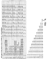
- the mapping for the Map M1 is shown in FIG. 3.
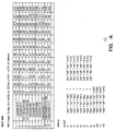
- the actual mapping of the Map M2 is shown in FIG. 4A and FIG. 4B.
- the 10-bit set v (v1 . . .v10) takes on the values (a3, a4, a5, a6, a7, a8, a9, a10, a11, a12).
- the table of FIG. 7 completes the description of the Map F. For example, if A1 is in the set G and A2 is in the set GG, then b 1 1. . .b 1 11 is M1(A1); b 1 12 is a 1 12; e1 is 1; b 2 1 is a 2 1; b 2 2 is a 2 2; and b 2 3b 2 4. . .b 2 12 is M2(A2).
- the current code-word is passed through the pre-coder 14A and the final state of the pre-coder is the initial state for the computation of e2 of the next code-word.
- the decoder 20A is a block map, which inverts the encoder.
- the decoder 20A receives 26 bits, (b 1 1 b 1 2....b 1 12) e1 (b 2 1 b 2 2...b 2 12) e2, and it outputs a 24 bit data, (a 1 1 a 1 2....a 1 12)(a 2 1 a 2 2...a 2 12).
- the decoder can be characterized by a map FF, where
- the map MM2 maps 10 bits (v1. . .v10) to twelve bits (a1. . .a12).
- a rate 48/51 trellis code according to a second embodiment of the invention may be generated from the 24/26 trellis code described above.
- the trellis code according to this embodiment has four (4) bytes error propagation due to EPRML minimum distance channel errors, a minimum of twelve (12) transitions per code word and a maximum of twelve (12) consecutive zeroes.
- FIG. 9A illustrates a block diagram of an encoder 12B according to this embodiment.
- the encoder 12B according to this embodiment includes a pair of Maps FA and FB, which are characterized similarly to the Map F described above.
- a Map fa is provided, as will be explained in greater detail below.
- a decoder 20B according to this embodiment is shown in FIG. 9B.
- the decoder 20B includes a pair of maps FFA and FFB, which are generally similar to the Map FF described above.
- the encoder 12B is characterized as follows:
- Encoding for the first 25 code-word bits may begin after 24 data bits are received. Thus, it is not necessary to receive all 48 data bits to begin coding.
- the decoder 20B is characterized as follows:
- Decoding for the first 24 data bits may begin after 25 code-word bits are received. Thus, it is not necessary to receive all 51 code word bits to begin decoding.
- a 48/51 trellis code according to another embodiment of the invention is described.
- a rate 48/51 trellis code is provided, with four (4) bytes error propagation due to EPRML minimum distance channel errors, a minimum of fourteen (14) transitions per code word and a maximum of eleven (11) consecutive zeroes.
- the code, TC, encoder is characterized as follows:
- a 1 1 is the first bit received and b 1 1 is the first bit transmitted.
- the pre-coder 14 has an even number of ones (1) every 51 bits that span the image of a code-word. Specifically, if
- the encoder for the Code C includes an encoder 12C characterized by a Map F1, which is further characterized by a Map M3, as will be explained in greater detail below.
- the Code C decoder 20C (FIG. 10B), in turn, may be characterized by a Map FF1, which is further characterized by a Map MM3, as will also be explained in greater detail below.
- the code C encoder 12C may be embodied as a finite state machine that receives 24-bit data
- the encoder 12C can be characterized by a map F1, where
- the decoder 20C can be characterized by a map FF1, where
- a map M3 is used to specify the map F1.
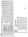
- the Map M3 maps 12 bits into 10 bits as shown in the table of FIGS. 11A and 11B. Then, the table of FIG. 13 completes the characterization of the Map F1.
- the Code C decoder 20C is a block map, which inverts the encoder.
- the decoder receives 25 bits, (b 1 1 b 1 2....b 1 12) e1 (b 2 1 b 2 2...b 2 12), and it outputs a 24 bit data, (a 1 1 a 1 2....a 1 12)(a 2 1 a 2 2...a 2 12).
- a map MM3 is used to characterize the map FF1.
- the map MM is shown in FIGS. 12A and 12B.
- the table of FIG. 13 completes the characterization of the map FF1 from the map MM2.
- the rate 24/25 code, C, described above is used to generate a trellis code, TC, having a rate 48/51.
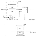
- Block diagrams of a Code TC encoder and decoder are shown in FIG. 15A and FIG. 15B, respectively.
- the Code TC encoder 12D includes a pair of Maps F1A and F1B, similar to the Map F1 described above.
- a Map f2 is provided, which will be explained in greater detail below.
- the decoder 20D is characterized by a pair of Maps FF1A and FF1B, similar to the Map FF1 described above.
Landscapes
- Engineering & Computer Science (AREA)
- Signal Processing (AREA)
- Computer Networks & Wireless Communication (AREA)
- Physics & Mathematics (AREA)
- Spectroscopy & Molecular Physics (AREA)
- Error Detection And Correction (AREA)
- Signal Processing For Digital Recording And Reproducing (AREA)
Abstract
Description
- initial state
- Sinitial =(state1 state2 state3), where statek, k=1,2, and 3, is the output of the pre-coder at time n-k,
- output
- y = x+state1+state2+state3 (mod 2), and
- final state
- Sfinal = (y state1 state2).
| C1 = { (a1..a12): a2=a3, a4=a5, a6=a7 } | (has 29 points) |
| C2 = { (a1..a12): a1=a2, a3=a4, a5=a6, a7=a8 } | (has 28 points) |
| C3 = { (a1..a12): a2=a3 = a4 = a5 = a6 } | (has 28 points) |
| C4 ={(a1..a12): a1+a2+..+a12 <=1 } | (has 12+1=13 points) |
- LEMMA 1 B=C.
- LEMMA 2 Bi's are pair-wise disjoint.
- R1=V1
- R2=V2 ∩ V1'
- R3=V3 ∩ V2' ∩ V1'
| E1 ={(a1..a12): a4=a5, a6=a7, a8=a9 , a10=a11} | (has 28 points) |
| E2 = {(a1..a12): a3=a4, a5=a6, a7=a8, a9=a10 } | (has 28 points) |
| E3 = {(a1..a12): a4=a5 = a6 = a7 = a8=a9=a10 } | (has 26 points) |
| E4 ={(a1..a12): a1+a2+..+a12 <=2} | (has 66+12+1=79 points) |
| E5 ={(a1..a12): a6+a7+a8+a9+a10+a11+a12=0} |
- LEMMA 1 E=D.
- LEMMA 2 Di's are pair-wise disjoint.
where
where
where the Maps FFA and FFB are as described above with reference to the Map FF (with e3 used for parity purposes in the Viterbi decoder).
| C1 = {(a1..a12): a2=a3, a4=a5, a6=a7, a8=a9 } | (has 28 points) |
| C2 = { (a1..a12): a3=a4, a5=a6, a7=a8, a9=a10 } | (has 28 points) |
| C3 ={(a1..a12): a3 = a4 = a5 = a6 = a7 a8 = a9} | (has 26 points) |
| C4 = {(a1..a12): a1+a2+..+a12 <=2 } | (has 66+12+1=79 points) |
| C5 = {(a1..a12): a1+a2+..+a6 =0} ∩ C1' ∩ C2' ∩ C3' ∩ C4' |
where
where the maps FF1A and FF1B are as the map FF1 described above (and with e3 used for parity purposes in the Viterbi decoder).
Claims (10)
- An extended partial response maximum likelihood (EPRML) channel, comprising:an encoder coupled to receive an input signal and implementing a rate 24/26 trellis code having three (3) bytes error propagation due to EPRML minimum distance channel errors;a precoder coupled to receive a coded signal from said encoder, perform a precoding operation on said coded signal;an extended partial response (EPR) channel coupled to receive an output from said precoder;a detector for detecting an output of said EPR channel; anda decoder coupled to receive an output of said detector for inverting said encoder.
- An EPRML channel according to Claim 1, wherein said encoder has a minimum of six (6) transitions per code word.
- An EPRML channel according to Claim 1, wherein said encoder has a maximum of twelve (12) consecutive zeroes.
- An EPRML channel according to Claim 1, wherein said encoder implements a rate 48/51 trellis code having four (4) bytes error propagation due to EPRML minimum distance channel errors using a concatenation of said rate 24/26 trellis code.
- An EPRML channel according to Claim 4, wherein said encoder has a minimum of twelve (12) transitions per code word.
- An EPRML channel according to Claim 4, wherein said encoder has a maximum of twelve (12) consecutive zeroes.
- An extended partial response maximum likelihood (EPRML) channel, comprising:an encoder coupled to receive an input signal and implementing a rate 48/51 trellis code having four (4) bytes error propagation due to EPRML minimum distance channel errors;a precoder coupled to receive a coded signal from said encoder, perform a precoding operation on said coded signal;an extended partial response (EPR) channel coupled to receive an output from said precoder;a detector for detecting an output of said EPR channel; anda decoder coupled to receive an output of said detector for inverting said encoder.
- An EPRML channel according to Claim 7, wherein said encoder has a minimum of fourteen (14) transitions per code word.
- An EPRML channel according to Claim 7, wherein said encoder has a maximum of eleven (11) consecutive zeroes.
- An extended partial response maximum likelihood (EPRML) channel, comprising:an encoder coupled to receive an input signal and implementing a trellis code including a partitioning into at least first and second maps;a precoder coupled to receive a coded signal from said encoder, perform a precoding operation on said coded signal;an extended partial response (EPR) channel coupled to receive an output from said precoder;a detector for detecting an output of said EPR channel; anda decoder coupled to receive an output of said detector for inverting said encoder.
Applications Claiming Priority (2)
| Application Number | Priority Date | Filing Date | Title |
|---|---|---|---|
| US09/347,598 US6408419B1 (en) | 1999-07-01 | 1999-07-01 | Trellis code for extended partial response maximum likelihood (EPRML) channel |
| US347598 | 1999-07-01 |
Publications (3)
| Publication Number | Publication Date |
|---|---|
| EP1065852A2 true EP1065852A2 (en) | 2001-01-03 |
| EP1065852A3 EP1065852A3 (en) | 2003-12-03 |
| EP1065852B1 EP1065852B1 (en) | 2006-01-11 |
Family
ID=23364404
Family Applications (1)
| Application Number | Title | Priority Date | Filing Date |
|---|---|---|---|
| EP00113457A Expired - Lifetime EP1065852B1 (en) | 1999-07-01 | 2000-06-24 | Trellis code for extended partial response maximum likelihood (EPRML) channel |
Country Status (6)
| Country | Link |
|---|---|
| US (1) | US6408419B1 (en) |
| EP (1) | EP1065852B1 (en) |
| JP (1) | JP2001053623A (en) |
| KR (1) | KR100727690B1 (en) |
| DE (1) | DE60025413T2 (en) |
| SG (1) | SG87896A1 (en) |
Families Citing this family (4)
| Publication number | Priority date | Publication date | Assignee | Title |
|---|---|---|---|---|
| US6718502B1 (en) * | 2000-08-11 | 2004-04-06 | Data Storage Institute | Precoders for partial response channels |
| KR100399353B1 (en) * | 2001-07-13 | 2003-09-26 | 삼성전자주식회사 | Non-volatile semiconductor memory device with time-division sense function and read method thereof |
| KR100559730B1 (en) | 2003-09-22 | 2006-03-15 | 삼성전자주식회사 | Method and apparatus for data encoding / decoding for recording system |
| US8276038B2 (en) * | 2007-08-03 | 2012-09-25 | International Business Machines Corporation | Data storage systems |
Family Cites Families (36)
| Publication number | Priority date | Publication date | Assignee | Title |
|---|---|---|---|---|
| CH609510A5 (en) | 1976-06-18 | 1979-02-28 | Ibm | |
| FR2565440B1 (en) | 1984-06-01 | 1986-09-05 | Adret Electronique | FREQUENCY SYNTHESIZER STAGE COMPRISING TWO PHASE LOCKED LOOPS, THE SECOND OF WHICH MULTIPLIES THE FREQUENCY OF THE FIRST BY A FACTOR NEAR THE UNIT. |
| US4707681A (en) * | 1986-04-24 | 1987-11-17 | International Business Machines Corporation | Method and apparatus for implementing optimum PRML codes |
| US5040191A (en) | 1987-02-24 | 1991-08-13 | Codex Corporation | Partial response channel signaling systems |
| US4939555A (en) | 1987-05-13 | 1990-07-03 | At&T Bell Laboratories | Trellis coding arrangement |
| US4802009A (en) | 1987-07-13 | 1989-01-31 | Rca Licensing Corporation | Digitally controlled phase locked loop system |
| US4873701A (en) | 1987-09-16 | 1989-10-10 | Penril Corporation | Modem and method for 8 dimensional trellis code modulation |
| US4888775A (en) | 1988-03-18 | 1989-12-19 | International Business Machines Corporation | Trellis codes for partial response channels |
| US4888779A (en) | 1988-03-18 | 1989-12-19 | International Business Machines Corporation | Matched spectral null trellis codes for partial response channels |
| DE3910739C3 (en) | 1989-04-03 | 1996-11-21 | Deutsche Forsch Luft Raumfahrt | Method for generalizing the Viterbi algorithm and means for performing the method |
| US5159610A (en) | 1989-05-12 | 1992-10-27 | Codex Corporation | Trellis precoding for modulation systems |
| US5111483A (en) | 1989-08-07 | 1992-05-05 | Motorola, Inc. | Trellis decoder |
| US5095484A (en) | 1989-11-13 | 1992-03-10 | International Business Machines Company Corporation | Phase invariant rate 8/10 matched spectral null code for PRML |
| US5214672A (en) | 1990-04-06 | 1993-05-25 | Codex Corporation | Trellis precoding for fractional bits/baud |
| US5052031A (en) | 1990-08-14 | 1991-09-24 | At&T Bell Laboratories | Phase locked loop including non-integer multiple frequency reference signal |
| US5301209A (en) | 1991-10-09 | 1994-04-05 | At&T Bell Laboratories | Multidimensional trellis-coded modulation for fading channels |
| US5327440A (en) | 1991-10-15 | 1994-07-05 | International Business Machines Corporation | Viterbi trellis coding methods and apparatus for a direct access storage device |
| US5260703A (en) | 1992-08-27 | 1993-11-09 | Quantum Corporation | Data encoding and decoding within PRML class IV sampling data detection channel of disk drive |
| US5424881A (en) | 1993-02-01 | 1995-06-13 | Cirrus Logic, Inc. | Synchronous read channel |
| US5844922A (en) | 1993-02-22 | 1998-12-01 | Qualcomm Incorporated | High rate trellis coding and decoding method and apparatus |
| US5497384A (en) | 1993-12-29 | 1996-03-05 | International Business Machines Corporation | Permuted trellis codes for input restricted partial response channels |
| US5619539A (en) | 1994-02-28 | 1997-04-08 | International Business Machines Corporation | Data detection methods and apparatus for a direct access storage device |
| US5490091A (en) | 1994-03-01 | 1996-02-06 | Guzik Technical Enterprises, Inc. | Histograms of processed noise samples for measuring error rate of a PRML data detection channel |
| JPH08329619A (en) | 1994-10-27 | 1996-12-13 | Hitachi Ltd | Data reproducing method, data reproducing device, and data reproducing circuit |
| US5621761A (en) * | 1994-12-09 | 1997-04-15 | General Instrument Corporation Of Delaware | Rotationally invariant trellis coding incorporating transparent binary convolutional codes |
| US5691993A (en) | 1995-06-07 | 1997-11-25 | Seagate Technology, Inc. | Rate 4/5 trellis code for PR4 channels with improved error propagation |
| US5521945A (en) | 1995-06-30 | 1996-05-28 | Quantum Corporation | Reduced complexity EPR4 post-processor for sampled data detection |
| US5809080A (en) | 1995-10-10 | 1998-09-15 | Mitel Semiconductor Americas Inc. | System and method for coding partial response channels with noise predictive Viterbi detectors |
| US5726818A (en) | 1995-12-05 | 1998-03-10 | Cirrus Logic, Inc. | Magnetic disk sampled amplitude read channel employing interpolated timing recovery for synchronous detection of embedded servo data |
| US5841818A (en) | 1996-01-17 | 1998-11-24 | Chung-Chin Chen | Decoding method for trellis codes employing a convolutional processor |
| US5809081A (en) | 1996-05-20 | 1998-09-15 | Mitel Semiconductor Americas Inc. | System and method for encoding data such that after precoding the data has a pre-selected parity structure |
| US5771127A (en) | 1996-07-29 | 1998-06-23 | Cirrus Logic, Inc. | Sampled amplitude read channel employing interpolated timing recovery and a remod/demod sequence detector |
| US5857002A (en) | 1996-08-16 | 1999-01-05 | International Business Machines Corporation | PRML channel with EPR4 equalization and clocking |
| US5757294A (en) * | 1996-12-31 | 1998-05-26 | Quantum Corporation | Rate 24/25 modulation code for PRML recording channels |
| US6154870A (en) * | 1997-06-04 | 2000-11-28 | Seagate Technology Llc | Signal error-correction system and method |
| US6035435A (en) * | 1997-09-30 | 2000-03-07 | Datapath Systems, Inc. | Method and apparatus for encoding a binary signal |
-
1999
- 1999-07-01 US US09/347,598 patent/US6408419B1/en not_active Expired - Lifetime
-
2000
- 2000-06-24 EP EP00113457A patent/EP1065852B1/en not_active Expired - Lifetime
- 2000-06-24 DE DE60025413T patent/DE60025413T2/en not_active Expired - Lifetime
- 2000-06-30 JP JP2000199374A patent/JP2001053623A/en active Pending
- 2000-07-01 KR KR1020000037544A patent/KR100727690B1/en not_active Expired - Fee Related
- 2000-07-01 SG SG200003674A patent/SG87896A1/en unknown
Also Published As
| Publication number | Publication date |
|---|---|
| US6408419B1 (en) | 2002-06-18 |
| KR100727690B1 (en) | 2007-06-13 |
| JP2001053623A (en) | 2001-02-23 |
| SG87896A1 (en) | 2002-04-16 |
| DE60025413T2 (en) | 2006-08-24 |
| DE60025413D1 (en) | 2006-04-06 |
| EP1065852B1 (en) | 2006-01-11 |
| KR20010021043A (en) | 2001-03-15 |
| EP1065852A3 (en) | 2003-12-03 |
Similar Documents
| Publication | Publication Date | Title |
|---|---|---|
| US5608397A (en) | Method and apparatus for generating DC-free sequences | |
| US5196849A (en) | Method and apparatus for implementing PRML codes with maximum ones | |
| US6154870A (en) | Signal error-correction system and method | |
| KR100370416B1 (en) | Encoding / Decoding Method for Recording / Reproducing High Density Data and Its Apparatus | |
| EP0830678A1 (en) | Trellis code with improved error propagation | |
| KR100403946B1 (en) | Data encoding method and apparatus | |
| JPH036699B2 (en) | ||
| US6909385B2 (en) | Method and apparatus for suppressing low frequency content in digital data | |
| JP3261085B2 (en) | How to decode a sequence of samples | |
| Cai et al. | On the design of spectrum shaping codes for high-density data storage | |
| US6400288B1 (en) | Method and apparatus for generating code words with shifted tribit error protection | |
| US6526530B1 (en) | Method and apparatus for encoding data incorporating check bits and maximum transition run constraint | |
| US6204781B1 (en) | General rate N/(N+1) (0, G) code construction for data coding | |
| KR100987658B1 (en) | Stable Disparity Channel Code for DC Control | |
| KR100408532B1 (en) | PRML code generation method in data storage device | |
| US5739783A (en) | Data recording apparatus | |
| US6408419B1 (en) | Trellis code for extended partial response maximum likelihood (EPRML) channel | |
| JP2002539706A (en) | Decoding to encode an n-bit source word into a corresponding m-bit channel word and vice versa such that the conversion is parity inversion | |
| JP3858392B2 (en) | Encoding circuit, encoding method, digital signal transmission apparatus, and digital magnetic recording apparatus | |
| JP2000134101A (en) | Coding circuit | |
| JP3896661B2 (en) | Trellis encoding method | |
| JP3453084B2 (en) | Apparatus and method for providing a punctured maximum transition code | |
| JP3748606B2 (en) | Error management code protection communication transmission system | |
| JP3882308B2 (en) | Code division method | |
| US7268707B2 (en) | Coding device and decoding device |
Legal Events
| Date | Code | Title | Description |
|---|---|---|---|
| PUAI | Public reference made under article 153(3) epc to a published international application that has entered the european phase |
Free format text: ORIGINAL CODE: 0009012 |
|
| AK | Designated contracting states |
Kind code of ref document: A2 Designated state(s): AT BE CH CY DE DK ES FI FR GB GR IE IT LI LU MC NL PT SE |
|
| AX | Request for extension of the european patent |
Free format text: AL;LT;LV;MK;RO;SI |
|
| PUAL | Search report despatched |
Free format text: ORIGINAL CODE: 0009013 |
|
| AK | Designated contracting states |
Kind code of ref document: A3 Designated state(s): AT BE CH CY DE DK ES FI FR GB GR IE IT LI LU MC NL PT SE |
|
| AX | Request for extension of the european patent |
Extension state: AL LT LV MK RO SI |
|
| RIC1 | Information provided on ipc code assigned before grant |
Ipc: 7G 11B 20/10 B Ipc: 7H 04L 1/00 B Ipc: 7H 04L 25/03 B Ipc: 7H 04L 25/497 A |
|
| 17P | Request for examination filed |
Effective date: 20031218 |
|
| RAP1 | Party data changed (applicant data changed or rights of an application transferred) |
Owner name: INFINEON TECHNOLOGIES AG |
|
| 17Q | First examination report despatched |
Effective date: 20040330 |
|
| AKX | Designation fees paid |
Designated state(s): DE FR GB IT |
|
| GRAP | Despatch of communication of intention to grant a patent |
Free format text: ORIGINAL CODE: EPIDOSNIGR1 |
|
| GRAS | Grant fee paid |
Free format text: ORIGINAL CODE: EPIDOSNIGR3 |
|
| GRAA | (expected) grant |
Free format text: ORIGINAL CODE: 0009210 |
|
| AK | Designated contracting states |
Kind code of ref document: B1 Designated state(s): DE FR GB IT |
|
| REF | Corresponds to: |
Ref document number: 60025413 Country of ref document: DE Date of ref document: 20060406 Kind code of ref document: P |
|
| ET | Fr: translation filed | ||
| PLBE | No opposition filed within time limit |
Free format text: ORIGINAL CODE: 0009261 |
|
| STAA | Information on the status of an ep patent application or granted ep patent |
Free format text: STATUS: NO OPPOSITION FILED WITHIN TIME LIMIT |
|
| 26N | No opposition filed |
Effective date: 20061012 |
|
| PGFP | Annual fee paid to national office [announced via postgrant information from national office to epo] |
Ref country code: IT Payment date: 20150622 Year of fee payment: 16 |
|
| REG | Reference to a national code |
Ref country code: FR Ref legal event code: PLFP Year of fee payment: 17 |
|
| PGFP | Annual fee paid to national office [announced via postgrant information from national office to epo] |
Ref country code: GB Payment date: 20160621 Year of fee payment: 17 |
|
| PGFP | Annual fee paid to national office [announced via postgrant information from national office to epo] |
Ref country code: FR Payment date: 20160627 Year of fee payment: 17 |
|
| PGFP | Annual fee paid to national office [announced via postgrant information from national office to epo] |
Ref country code: DE Payment date: 20160816 Year of fee payment: 17 |
|
| PG25 | Lapsed in a contracting state [announced via postgrant information from national office to epo] |
Ref country code: IT Free format text: LAPSE BECAUSE OF NON-PAYMENT OF DUE FEES Effective date: 20160624 |
|
| REG | Reference to a national code |
Ref country code: DE Ref legal event code: R119 Ref document number: 60025413 Country of ref document: DE |
|
| GBPC | Gb: european patent ceased through non-payment of renewal fee |
Effective date: 20170624 |
|
| REG | Reference to a national code |
Ref country code: FR Ref legal event code: ST Effective date: 20180228 |
|
| PG25 | Lapsed in a contracting state [announced via postgrant information from national office to epo] |
Ref country code: DE Free format text: LAPSE BECAUSE OF NON-PAYMENT OF DUE FEES Effective date: 20180103 Ref country code: GB Free format text: LAPSE BECAUSE OF NON-PAYMENT OF DUE FEES Effective date: 20170624 |
|
| PG25 | Lapsed in a contracting state [announced via postgrant information from national office to epo] |
Ref country code: FR Free format text: LAPSE BECAUSE OF NON-PAYMENT OF DUE FEES Effective date: 20170630 |