EP1065812A1 - Optical repeater and output level control method - Google Patents
Optical repeater and output level control method Download PDFInfo
- Publication number
- EP1065812A1 EP1065812A1 EP00305437A EP00305437A EP1065812A1 EP 1065812 A1 EP1065812 A1 EP 1065812A1 EP 00305437 A EP00305437 A EP 00305437A EP 00305437 A EP00305437 A EP 00305437A EP 1065812 A1 EP1065812 A1 EP 1065812A1
- Authority
- EP
- European Patent Office
- Prior art keywords
- optical
- optical signal
- wdm
- wavelength
- pumping light
- Prior art date
- Legal status (The legal status is an assumption and is not a legal conclusion. Google has not performed a legal analysis and makes no representation as to the accuracy of the status listed.)
- Granted
Links
- 230000003287 optical effect Effects 0.000 title claims abstract description 306
- 238000000034 method Methods 0.000 title claims description 6
- 238000005086 pumping Methods 0.000 claims abstract description 48
- 239000013307 optical fiber Substances 0.000 claims abstract description 44
- 230000005540 biological transmission Effects 0.000 claims abstract description 25
- 238000010586 diagram Methods 0.000 description 12
- 238000001228 spectrum Methods 0.000 description 4
- 230000000694 effects Effects 0.000 description 2
- 239000000284 extract Substances 0.000 description 2
- 239000000835 fiber Substances 0.000 description 2
- 229910052691 Erbium Inorganic materials 0.000 description 1
- UYAHIZSMUZPPFV-UHFFFAOYSA-N erbium Chemical compound [Er] UYAHIZSMUZPPFV-UHFFFAOYSA-N 0.000 description 1
- 238000012544 monitoring process Methods 0.000 description 1
- 230000008054 signal transmission Effects 0.000 description 1
Images


Classifications
-
- H—ELECTRICITY
- H04—ELECTRIC COMMUNICATION TECHNIQUE
- H04B—TRANSMISSION
- H04B10/00—Transmission systems employing electromagnetic waves other than radio-waves, e.g. infrared, visible or ultraviolet light, or employing corpuscular radiation, e.g. quantum communication
- H04B10/29—Repeaters
- H04B10/291—Repeaters in which processing or amplification is carried out without conversion of the main signal from optical form
- H04B10/293—Signal power control
- H04B10/294—Signal power control in a multiwavelength system, e.g. gain equalisation
- H04B10/2942—Signal power control in a multiwavelength system, e.g. gain equalisation using automatic gain control [AGC]
-
- H—ELECTRICITY
- H01—ELECTRIC ELEMENTS
- H01S—DEVICES USING THE PROCESS OF LIGHT AMPLIFICATION BY STIMULATED EMISSION OF RADIATION [LASER] TO AMPLIFY OR GENERATE LIGHT; DEVICES USING STIMULATED EMISSION OF ELECTROMAGNETIC RADIATION IN WAVE RANGES OTHER THAN OPTICAL
- H01S3/00—Lasers, i.e. devices using stimulated emission of electromagnetic radiation in the infrared, visible or ultraviolet wave range
- H01S3/10—Controlling the intensity, frequency, phase, polarisation or direction of the emitted radiation, e.g. switching, gating, modulating or demodulating
- H01S3/13—Stabilisation of laser output parameters, e.g. frequency or amplitude
- H01S3/1301—Stabilisation of laser output parameters, e.g. frequency or amplitude in optical amplifiers
- H01S3/13013—Stabilisation of laser output parameters, e.g. frequency or amplitude in optical amplifiers by controlling the optical pumping
-
- H—ELECTRICITY
- H04—ELECTRIC COMMUNICATION TECHNIQUE
- H04J—MULTIPLEX COMMUNICATION
- H04J14/00—Optical multiplex systems
- H04J14/02—Wavelength-division multiplex systems
- H04J14/0221—Power control, e.g. to keep the total optical power constant
-
- H—ELECTRICITY
- H01—ELECTRIC ELEMENTS
- H01S—DEVICES USING THE PROCESS OF LIGHT AMPLIFICATION BY STIMULATED EMISSION OF RADIATION [LASER] TO AMPLIFY OR GENERATE LIGHT; DEVICES USING STIMULATED EMISSION OF ELECTROMAGNETIC RADIATION IN WAVE RANGES OTHER THAN OPTICAL
- H01S3/00—Lasers, i.e. devices using stimulated emission of electromagnetic radiation in the infrared, visible or ultraviolet wave range
- H01S3/10—Controlling the intensity, frequency, phase, polarisation or direction of the emitted radiation, e.g. switching, gating, modulating or demodulating
- H01S3/13—Stabilisation of laser output parameters, e.g. frequency or amplitude
- H01S3/1305—Feedback control systems
Definitions
- the present invention relates to an optical signal repeater at a wavelength division multiplex (WDM) system, in particular, which can control an output level of each optical signal of WDM optical signals to be outputted to a designated value, and an output level control method used this repeater.
- WDM wavelength division multiplex
- Japanese Patent Application Laid-Open No. HEI 9-326770 discloses a linear repeater using for a WDM system.
- a part of the amplified optical signals is split at an optical splitter.
- These WDM optical signals split at the optical splitter are inputted to a variable wavelength optical filter that can variably control transmitting wavelength to be transmitted in each optical signal.
- An optical signal transmitted through this variable wavelength optical filter is inputted to an automatic gain control (AGC) section, and the gain of each optical signal is controlled to a designated value by monitoring the power level of the optical signal inputted to the AGC section.
- AGC automatic gain control
- Fig. 1 is a block diagram showing a conventional optical signal repeater using for a WDM system.
- This conventional optical signal repeater consists of an optical fiber transmission line 11 in which WDM optical signals are transmitted, an optical amplifier 12 which amplifies the transmitted WDM optical signals, an optical multiplexer 13, an optical splitter 14 which splits the amplified WDM optical signals outputted from the optical amplifier 12 into two parts, a pumping laser diode (LD) 17 being a pumping light source, a variable wavelength optical filter 18 which can variably control transmitting wavelength of the WDM optical signals to be transmitted in each optical signal, and an AGC section 19.
- Fig. 2 is a block diagram showing gain control operation of the conventional optical signal repeater shown in Fig. 1. In Fig.
- a broken line from the pumping LD 17 shows a flow of pumping light and the other broken lines show flows of optical signals.
- spectra of the optical signals are also shown in Fig. 2. In these spectra, the vertical axis shows the optical power level and the horizontal axis shows the optical wavelength.
- the output level of each optical signal of the transmitted WDM optical signals is controlled to a designated level by using the following method. That is, a part of the WDM optical signals outputted from the optical amplifier 12 is split at the optical splitter 14, and each optical signal of the split WDM optical signals is transmitted through the variable wavelength optical filter 18. The transmitted optical signal is inputted to the AGC section 19, and the AGC section 19 controls the output from the pumping LD 17 so that the power level of each optical signal inputted to the AGC section 19 is kept in a designated level.
- the AGC section 19 controls the output of the pumping LD 17 so that the output level of each optical signal of the WDM optical signals becomes a designated level, without any relation with the power level of the WDM optical signals inputted to the optical signal repeater. Therefore, each optical signal transmitting through the optical fiber transmission line 11 is amplified to a designated level without any relation with the power levels of the inputted WDM optical signals at the optical fiber transmission line 11. Consequently, it is possible to realize a WDM optical signal transmission system in which the fluctuation of the outputting optical power level of each optical signal is reduced.
- variable wavelength optical filter 18 provides a driving unit (not shown) which varies the transmitting wavelength, however, there is a problem that this driving unit does not have high reliability.
- variable wavelength optical filter 18 it is difficult to make the transmitting wavelength band narrow, therefore optical signals adjacent to the optical signal to be transmitted leak and the leaked adjacent optical signals are inputted to the AGC section 19. As a result, it is difficult to monitor the input level of each optical signal to the AGC section 19 precisely.
- the adjacent wavelengths are positioned at the far positions from the optical signal to be transmitted. Therefore, there is a problem that the number of the wavelengths to be multiplexed is limited in the amplifying wavelength band.
- an optical signal repeater which is used at an optical fiber transmission system providing with an optical fiber transmission line, an optical transmitter, and an optical receiver.
- the optical signal repeater provides an optical signal amplifying means for amplifying wavelength division multiplexed (WDM) optical signals transmitted from the optical transmitter via the optical fiber transmission line, a pumping light source which outputs pumping light using for amplifying the WDM optical signals, an optical signal multiplexer which transmits the pumping light to the optical signal amplifying means, an optical splitter which splits the amplified WDM optical signals into two parts, a wavelength selection type reflection means which reflects only an optical signal having a specified wavelength in one part of the amplified WDM optical signals split at the optical splitter, and an automatic output level controller to which the optical signal having the specified wavelength is inputted and which controls the pumping light outputting from the pumping light source so that the power level of the optical signal having the specified wavelength reflected from the wavelength selection type reflection means becomes a designated level.
- a reflected optical signal for amplifying wavelength division multiplexed
- the optical splitter provides the reflected optical signal transmitting means.
- the wavelength selection type reflection means is an optical fiber grating filter.
- an optical signal output level control method which provides the steps of; inputting WDM optical signals transmitted from an optical transmitter via an optical fiber transmission line to an optical signal amplifying means, inputting pumping light to the optical signal amplifying means, amplifying the inputted WDM optical signals, splitting the amplified WDM optical signals into two parts, outputting main part of the split amplified WDM optical signals to an optical receiver via said optical fiber transmission line, inputting one part of the split amplified WDM optical signals to a wavelength selection type reflection means, reflecting only an optical signal having a specified wavelength in one part of the split amplified WDM optical signals at the wavelength selection type reflection means, inputting the optical signal having the specified wavelength to an automatic output level controller, and controlling the pumping light so that the power level of the optical signal having the specified wavelength becomes a designated level at the automatic output level controller.
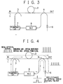
- FIG. 3 is a block diagram showing a first embodiment of an optical signal repeater using for a WDM system of the present invention.
- This optical signal repeater is used for an optical fiber transmission system that provides an optical fiber transmission line, an optical transmitter that transmits WDM optical signals to the optical fiber transmission line, and an optical receiver that receives the transmitted optical signals.
- the optical signal repeater of the present invention consists of an optical fiber transmission line 1, an optical amplifier 2, an optical multiplexer 3, an optical splitter 4, an optical fiber grating filter (wavelength selection type reflection means) 5, an automatic output level controller (ALC) 6, and a pumping laser diode (LD) 7 being a pumping light source.
- ALC automatic output level controller
- LD pumping laser diode
- the optical amplifier 2 amplifies WDM optical signals, whose wavelengths are different from one another, transmitting through the optical fiber transmission line 1.
- This optical amplifier 2 is an optical amplifier that provides such as an erbium doped optical fiber.
- the optical multiplexer 3 is provided at the input side of the optical amplifier 2, and inputs pumping light from the pumping LD 7 to the optical amplifier 2 in which the pumping light is used for amplifying the inputted WDM optical signals.
- the optical splitter 4 is provided at the output side of the optical amplifier 2, and which splits the WDM optical signals amplified at the optical amplifier 2 into two parts. That is, the main part split at the optical splitter 4 is outputted to the optical receiver (not shown) via the optical fiber transmission line 1, and a part of the amplified WDM optical signals split at the optical splitter 4 is outputted to the optical fiber grating filter 5.
- the optical fiber grating filter 5 which reflects only an optical signal having a specified wavelength in the optical signals split at the optical splitter 4.
- the ALC 6 to which the optical signal having the specified wavelength is inputted and monitors the power level of this inputted optical signal and controls the power level of the inputted optical signal to a designated level by controlling the pumping light outputting from the pumping LD 7.
- the optical signal having the specified wavelength reflected at the optical fiber grating filter 5 is inputted to the ALC 6 via the optical splitter 4.
- the pumping LD 7 is positioned between the ALC 6 and the optical multiplexer 3.
- Fig. 4 is a block diagram showing operation of the first embodiment of the optical signal repeater of the present invention shown in Fig. 3. Referring to Fig. 4, the operation of the first embodiment of the present invention is explained.
- a broken line from the pumping LD 7 shows a flow of pumping light and the other broken lines show flows of optical signals.
- spectra of the optical signals are also shown in Fig. 4. In these spectra, the vertical axis shows the optical power level and the horizontal axis shows the optical wavelength.
- the inputted WDM optical signals are amplified at the optical amplifier 2 and outputted.
- the gain of the optical amplifier 2 is controlled by changing the power of the pumping light inputted to the optical amplifier 2.
- the optical splitter 4 splits the WDM optical signals amplified at the optical amplifier 2 into two parts.
- the main part of the amplified WDM optical signals is outputted to the optical receiver (not shown) via the optical fiber transmission line 1.
- a part of the amplified WDM optical signals is inputted to the optical fiber grating filter 5.
- the optical fiber grating filter 5 reflects only an optical signal having a specified wavelength in the WDM optical signals inputted to the optical fiber grating filter 5.
- the optical signal having the specified wavelength reflected at the optical fiber grating filter 5 is inputted to the ALC 6 via the optical splitter 4.
- the ALC 6 controls the output from the pumping LD 7 so that the power level of the optical signal inputting to the ALC 6 becomes always a designated level.
- the optical signal having the specified wavelength reflected at the optical fiber grating filter 5 is included in the WDM optical signals to be amplified. Therefore, the output level of each optical signal of the WDM optical signals does not change. And even when the number of the WDM optical signals does not change and the input level changes, the output level is controlled to a designated level.
- the optical signal repeater of the present invention only one optical signal having one wavelength is selected and extracted from the WDM optical signals and the output level of the selected and extracted only one optical signal is controlled to a designated level. Therefore, even when the number of the wavelengths of the inputted WDM optical signals changes, the output level at each wavelength can be kept in a designated level. And even when the number of the wavelengths does not change and the input level changes, the output level can be kept in a designated level.
- the wavelength to be selected and extracted is fixed, therefore a control means to vary the wavelength to be selected and extracted is not needed and the structure can be simple.
- an optical fiber grating filter which can make the reflecting wavelength band very narrow as a means for extracting a specified optical signal, it is possible to extracts only a desired optical signal precisely. Therefore, without any influence from adjacent optical signals, the output level can be controlled precisely.
- an optical fiber grating filter being one of fiber components
- the present invention can achieve high reliability compared with a system using a device such as lenses.
- the optical splitter 4 has two functions. That is, one function is to input the split optical signal to the optical fiber grating filter 5, and the other function is to transmit the optical signal having the specified wavelength reflected at the optical fiber grating filter 5 to the ALC 6. Therefore, the circuit structure can be simplified and the assembling time is shortened, consequently the optical signal repeater can be provided in a low cost.
- the optical signal repeater of the present invention as a wavelength selection type reflection means which makes only one optical signal having a specified wavelength reflect in the optical signals split at the optical splitter 4, the optical fiber grating filter 5 is used, consequently a variable wavelength optical filter used in the conventional optical signal repeater is not needed. Therefore, even when the number of the inputted WDM optical signals changes, the output level of each optical signal of the WDM optical signals does not change. Consequently, the high reliability can be achieved and the circuit structure can be simplified, and the optical signal repeater of the present invention can be applied to a system in which intervals among optical signals are relatively narrow.
- FIG. 5 is a block diagram showing the second embodiment of the optical signal repeater using for a WDM system of the present invention.
- the pumping light outputted from the pumping LD 7 is inputted to the back side of the optical amplifier 2.
- the optical splitter 4 which splits the amplified optical signals into two parts is disposed behind the optical multiplexer 3 which transmits the pumping light to the optical amplifier 2.
- Fig. 6 is a block diagram showing a third embodiment of the optical signal repeater using for a WDM system of the present invention.
- the third embodiment is explained.
- the pumping light outputted from the pumping LD 7 is inputted to the back side of the optical amplifier 2.
- the optical splitter 4 which splits the amplified optical signals into two parts is disposed in front of the optical multiplexer 3 which transmits the pumping light to the optical amplifier 2.
- This third embodiment achieves the same effect as the first embodiment achieves.
- the optical signal repeater of the present invention is used at an optical fiber transmission system providing with an optical fiber transmission line, an optical transmitter, and an optical receiver.
- the optical signal repeater provides an optical signal amplifying means for amplifying wavelength division multiplexed (WDM) optical signals transmitted from the optical transmitter via the optical fiber transmission line, a pumping light source which outputs pumping light using for amplifying the WDM optical signals, an optical signal multiplexer which transmits the pumping light to the optical signal amplifying means, an optical splitter which splits the amplified WDM optical signals into two parts, a wavelength selection type reflection means which reflects only an optical signal having a specified wavelength in one part of the amplified WDM optical signals split at the optical splitter, an automatic output level controller to which the optical signal having the specified wavelength is inputted and which controls the pumping light outputting from the pumping light source so that the power level of the optical signal having the specified wavelength reflected from the wavelength selection type reflection means becomes a designated level, and a reflected optical signal transmitting means which transmits the W
- the optical signal repeater selects and extracts one optical signal having a specified wavelength and controls the output level of the selected and extracted the optical signal having the specified wavelength, therefore even when the number of wavelengths of the inputted WDM optical signals changes, the output level of each optical signal can be kept in a designated level. And even when the number of the wavelengths does not change and the input level changes, the output level can be kept in a designated level.
- the wavelength to be selected and extracted is fixed, therefore a control means to vary the wavelength to be selected and extracted is not needed and the structure can be simple.
- the optical signal repeater of the present invention provides a wavelength selection type reflection means which can reflect only an optical signal having a specified wavelength. Therefore, the variable wavelength optical filter used in the conventional optical signal repeater is not needed, and even when the number of wavelengths of the inputted WDM optical signals changes, the output level of each optical signal of the inputted WDM optical signals does not change, the optical repeater is able to have high reliability, and its structure can be simplified. Moreover, the present invention is applicable to a system in which intervals among WDM optical signals are relatively narrow.
- an optical fiber grating filter which can make the reflecting wavelength band very narrow is used as a means for extracting a specified optical signal. Consequently, it is possible to extract only a desired optical signal precisely, and without any influence from adjacent optical signals, the output level can be controlled precisely.
- an optical fiber grating filter being one of fiber components
- the present invention can achieve high reliability compared with a system using a device such as lenses.
- the optical splitter has two functions. That is, one function is to input the split optical signal to the wavelength selection type reflection means, and the other function is to transmits the optical signal having the specified wavelength reflected at the wavelength selection type reflection means to the automatic output level controller. Therefore, the circuit structure can be simplified and the assembling time is shortened, consequently the optical signal repeater can be provided in a low cost.
Landscapes
- Physics & Mathematics (AREA)
- Electromagnetism (AREA)
- Engineering & Computer Science (AREA)
- Computer Networks & Wireless Communication (AREA)
- Signal Processing (AREA)
- Plasma & Fusion (AREA)
- Optics & Photonics (AREA)
- Optical Communication System (AREA)
- Lasers (AREA)
Abstract
Description
- The present invention relates to an optical signal repeater at a wavelength division multiplex (WDM) system, in particular, which can control an output level of each optical signal of WDM optical signals to be outputted to a designated value, and an output level control method used this repeater.
- Japanese Patent Application Laid-Open No. HEI 9-326770 discloses a linear repeater using for a WDM system. In this application, at an output stage of an optical amplifier in which WDM optical signals to be transmitted are amplified, a part of the amplified optical signals is split at an optical splitter. These WDM optical signals split at the optical splitter are inputted to a variable wavelength optical filter that can variably control transmitting wavelength to be transmitted in each optical signal. An optical signal transmitted through this variable wavelength optical filter is inputted to an automatic gain control (AGC) section, and the gain of each optical signal is controlled to a designated value by monitoring the power level of the optical signal inputted to the AGC section.
- Fig. 1 is a block diagram showing a conventional optical signal repeater using for a WDM system. This conventional optical signal repeater consists of an optical
fiber transmission line 11 in which WDM optical signals are transmitted, anoptical amplifier 12 which amplifies the transmitted WDM optical signals, anoptical multiplexer 13, anoptical splitter 14 which splits the amplified WDM optical signals outputted from theoptical amplifier 12 into two parts, a pumping laser diode (LD) 17 being a pumping light source, a variable wavelengthoptical filter 18 which can variably control transmitting wavelength of the WDM optical signals to be transmitted in each optical signal, and anAGC section 19. Fig. 2 is a block diagram showing gain control operation of the conventional optical signal repeater shown in Fig. 1. In Fig. 2, a broken line from the pumpingLD 17 shows a flow of pumping light and the other broken lines show flows of optical signals. And spectra of the optical signals are also shown in Fig. 2. In these spectra, the vertical axis shows the optical power level and the horizontal axis shows the optical wavelength. - At this conventional optical signal repeater, the output level of each optical signal of the transmitted WDM optical signals is controlled to a designated level by using the following method. That is, a part of the WDM optical signals outputted from the
optical amplifier 12 is split at theoptical splitter 14, and each optical signal of the split WDM optical signals is transmitted through the variable wavelengthoptical filter 18. The transmitted optical signal is inputted to theAGC section 19, and theAGC section 19 controls the output from the pumpingLD 17 so that the power level of each optical signal inputted to theAGC section 19 is kept in a designated level. - At this kind of optical signal output level control method, the
AGC section 19 controls the output of thepumping LD 17 so that the output level of each optical signal of the WDM optical signals becomes a designated level, without any relation with the power level of the WDM optical signals inputted to the optical signal repeater. Therefore, each optical signal transmitting through the opticalfiber transmission line 11 is amplified to a designated level without any relation with the power levels of the inputted WDM optical signals at the opticalfiber transmission line 11. Consequently, it is possible to realize a WDM optical signal transmission system in which the fluctuation of the outputting optical power level of each optical signal is reduced. - However, at the conventional optical signal repeater mentioned above, there are several problems. First, at the conventional optical signal repeater, a part of the optical signals is transmitted through the variable wavelength
optical filter 18 and inputted to theAGC section 19. And the variable wavelengthoptical filter 18 provides a driving unit (not shown) which varies the transmitting wavelength, however, there is a problem that this driving unit does not have high reliability. - Secondly, a circuit, which controls the transmitting wavelength through the variable wavelength
optical filter 18, is additionally required, as a result, the structure of the optical signal repeater becomes complex. - Thirdly, at the variable wavelength
optical filter 18, it is difficult to make the transmitting wavelength band narrow, therefore optical signals adjacent to the optical signal to be transmitted leak and the leaked adjacent optical signals are inputted to theAGC section 19. As a result, it is difficult to monitor the input level of each optical signal to theAGC section 19 precisely. - Moreover, in order to avoid making the adjacent optical signals input to the
AGC section 19, it is required that the adjacent wavelengths are positioned at the far positions from the optical signal to be transmitted. Therefore, there is a problem that the number of the wavelengths to be multiplexed is limited in the amplifying wavelength band. - According to a first aspect of the present invention, there is provided an optical signal repeater, which is used at an optical fiber transmission system providing with an optical fiber transmission line, an optical transmitter, and an optical receiver. The optical signal repeater provides an optical signal amplifying means for amplifying wavelength division multiplexed (WDM) optical signals transmitted from the optical transmitter via the optical fiber transmission line, a pumping light source which outputs pumping light using for amplifying the WDM optical signals, an optical signal multiplexer which transmits the pumping light to the optical signal amplifying means, an optical splitter which splits the amplified WDM optical signals into two parts, a wavelength selection type reflection means which reflects only an optical signal having a specified wavelength in one part of the amplified WDM optical signals split at the optical splitter, and an automatic output level controller to which the optical signal having the specified wavelength is inputted and which controls the pumping light outputting from the pumping light source so that the power level of the optical signal having the specified wavelength reflected from the wavelength selection type reflection means becomes a designated level. A reflected optical signal transmitting means is preferably provided which transmits the optical signal having the specified wavelength reflected at the wavelength selection type reflection means to the automatic output level controller.
- Preferably the optical splitter provides the reflected optical signal transmitting means.
- Preferably the wavelength selection type reflection means is an optical fiber grating filter.
- According to a second aspect of the present invention, there is provided an optical signal output level control method, which provides the steps of; inputting WDM optical signals transmitted from an optical transmitter via an optical fiber transmission line to an optical signal amplifying means, inputting pumping light to the optical signal amplifying means, amplifying the inputted WDM optical signals, splitting the amplified WDM optical signals into two parts, outputting main part of the split amplified WDM optical signals to an optical receiver via said optical fiber transmission line, inputting one part of the split amplified WDM optical signals to a wavelength selection type reflection means, reflecting only an optical signal having a specified wavelength in one part of the split amplified WDM optical signals at the wavelength selection type reflection means, inputting the optical signal having the specified wavelength to an automatic output level controller, and controlling the pumping light so that the power level of the optical signal having the specified wavelength becomes a designated level at the automatic output level controller.
- The objects and features of the present invention will become more apparent from the consideration of the following detailed description taken in conjunction with the accompanying drawings in which:
- Fig. 1 is a block diagram showing a conventional optical signal repeater using for a WDM system;
- Fig. 2 is a block diagram showing gain control operation of the conventional optical signal repeater shown in Fig. 1;
- Fig. 3 is a block diagram showing a first embodiment of an optical signal repeater using for a WDM system of the present invention;
- Fig. 4 is a block diagram showing operation of the first embodiment of the optical signal repeater of the present invention shown in Fig.3;
- Fig. 5 is a block diagram showing a second embodiment of the optical signal repeater using for a WDM system of the present invention; and
- Fig. 6 is a block diagram showing a third embodiment of the optical signal repeater using for a WDM system of the present invention.
-
- Referring now to the drawings, embodiments of the present invention are explained in detail. Fig. 3 is a block diagram showing a first embodiment of an optical signal repeater using for a WDM system of the present invention. This optical signal repeater is used for an optical fiber transmission system that provides an optical fiber transmission line, an optical transmitter that transmits WDM optical signals to the optical fiber transmission line, and an optical receiver that receives the transmitted optical signals.
- As shown in Fig. 3, the optical signal repeater of the present invention consists of an optical
fiber transmission line 1, anoptical amplifier 2, anoptical multiplexer 3, anoptical splitter 4, an optical fiber grating filter (wavelength selection type reflection means) 5, an automatic output level controller (ALC) 6, and a pumping laser diode (LD) 7 being a pumping light source. - The
optical amplifier 2 amplifies WDM optical signals, whose wavelengths are different from one another, transmitting through the opticalfiber transmission line 1. Thisoptical amplifier 2 is an optical amplifier that provides such as an erbium doped optical fiber. - The
optical multiplexer 3 is provided at the input side of theoptical amplifier 2, and inputs pumping light from the pumpingLD 7 to theoptical amplifier 2 in which the pumping light is used for amplifying the inputted WDM optical signals. And theoptical splitter 4 is provided at the output side of theoptical amplifier 2, and which splits the WDM optical signals amplified at theoptical amplifier 2 into two parts. That is, the main part split at theoptical splitter 4 is outputted to the optical receiver (not shown) via the opticalfiber transmission line 1, and a part of the amplified WDM optical signals split at theoptical splitter 4 is outputted to the optical fiber grating filter 5. - The optical fiber grating filter 5 which reflects only an optical signal having a specified wavelength in the optical signals split at the
optical splitter 4. TheALC 6 to which the optical signal having the specified wavelength is inputted and monitors the power level of this inputted optical signal and controls the power level of the inputted optical signal to a designated level by controlling the pumping light outputting from the pumpingLD 7. In this, the optical signal having the specified wavelength reflected at the optical fiber grating filter 5 is inputted to theALC 6 via theoptical splitter 4. The pumpingLD 7 is positioned between theALC 6 and theoptical multiplexer 3. - Fig. 4 is a block diagram showing operation of the first embodiment of the optical signal repeater of the present invention shown in Fig. 3. Referring to Fig. 4, the operation of the first embodiment of the present invention is explained. In Fig. 4, a broken line from the pumping
LD 7 shows a flow of pumping light and the other broken lines show flows of optical signals. And spectra of the optical signals are also shown in Fig. 4. In these spectra, the vertical axis shows the optical power level and the horizontal axis shows the optical wavelength. - First, when WDM optical signals transmitted from the optical transmitter (not shown) via the optical
fiber transmission line 1 are inputted to the optical signal repeater, the inputted WDM optical signals are amplified at theoptical amplifier 2 and outputted. In this, the gain of theoptical amplifier 2 is controlled by changing the power of the pumping light inputted to theoptical amplifier 2. - Next, the
optical splitter 4 splits the WDM optical signals amplified at theoptical amplifier 2 into two parts. The main part of the amplified WDM optical signals is outputted to the optical receiver (not shown) via the opticalfiber transmission line 1. A part of the amplified WDM optical signals is inputted to the optical fiber grating filter 5. The optical fiber grating filter 5 reflects only an optical signal having a specified wavelength in the WDM optical signals inputted to the optical fiber grating filter 5. The optical signal having the specified wavelength reflected at the optical fiber grating filter 5 is inputted to theALC 6 via theoptical splitter 4. TheALC 6 controls the output from thepumping LD 7 so that the power level of the optical signal inputting to theALC 6 becomes always a designated level. - As mentioned above, by controlling the output level of an optical signal having a specified wavelength to a designated level, even when the number of the wavelengths of the inputted WDM optical signals changes, the optical signal having the specified wavelength reflected at the optical fiber grating filter 5 is included in the WDM optical signals to be amplified. Therefore, the output level of each optical signal of the WDM optical signals does not change. And even when the number of the WDM optical signals does not change and the input level changes, the output level is controlled to a designated level.
- At the first embodiment of the optical signal repeater of the present invention, only one optical signal having one wavelength is selected and extracted from the WDM optical signals and the output level of the selected and extracted only one optical signal is controlled to a designated level. Therefore, even when the number of the wavelengths of the inputted WDM optical signals changes, the output level at each wavelength can be kept in a designated level. And even when the number of the wavelengths does not change and the input level changes, the output level can be kept in a designated level.
- And the wavelength to be selected and extracted is fixed, therefore a control means to vary the wavelength to be selected and extracted is not needed and the structure can be simple. Moreover, by using an optical fiber grating filter which can make the reflecting wavelength band very narrow as a means for extracting a specified optical signal, it is possible to extracts only a desired optical signal precisely. Therefore, without any influence from adjacent optical signals, the output level can be controlled precisely.
- And as a means for selecting and extracting a wavelength, an optical fiber grating filter being one of fiber components is used, therefore the present invention can achieve high reliability compared with a system using a device such as lenses. And the
optical splitter 4 has two functions. That is, one function is to input the split optical signal to the optical fiber grating filter 5, and the other function is to transmit the optical signal having the specified wavelength reflected at the optical fiber grating filter 5 to theALC 6. Therefore, the circuit structure can be simplified and the assembling time is shortened, consequently the optical signal repeater can be provided in a low cost. - At the first embodiment of the optical signal repeater of the present invention, as a wavelength selection type reflection means which makes only one optical signal having a specified wavelength reflect in the optical signals split at the
optical splitter 4, the optical fiber grating filter 5 is used, consequently a variable wavelength optical filter used in the conventional optical signal repeater is not needed. Therefore, even when the number of the inputted WDM optical signals changes, the output level of each optical signal of the WDM optical signals does not change. Consequently, the high reliability can be achieved and the circuit structure can be simplified, and the optical signal repeater of the present invention can be applied to a system in which intervals among optical signals are relatively narrow. - Next, a second embodiment of the optical signal repeater of the present invention is explained. Fig. 5 is a block diagram showing the second embodiment of the optical signal repeater using for a WDM system of the present invention. As shown in Fig. 5, at the second embodiment, the pumping light outputted from the
pumping LD 7 is inputted to the back side of theoptical amplifier 2. And theoptical splitter 4 which splits the amplified optical signals into two parts is disposed behind theoptical multiplexer 3 which transmits the pumping light to theoptical amplifier 2. This second embodiment achieves the same effect as the first embodiment achieves. - Fig. 6 is a block diagram showing a third embodiment of the optical signal repeater using for a WDM system of the present invention. Referring to Fig. 6, the third embodiment is explained. At the third embodiment, as the same as the second embodiment, the pumping light outputted from the
pumping LD 7 is inputted to the back side of theoptical amplifier 2. And theoptical splitter 4 which splits the amplified optical signals into two parts is disposed in front of theoptical multiplexer 3 which transmits the pumping light to theoptical amplifier 2. This third embodiment achieves the same effect as the first embodiment achieves. - As mentioned above, the optical signal repeater of the present invention is used at an optical fiber transmission system providing with an optical fiber transmission line, an optical transmitter, and an optical receiver. The optical signal repeater provides an optical signal amplifying means for amplifying wavelength division multiplexed (WDM) optical signals transmitted from the optical transmitter via the optical fiber transmission line, a pumping light source which outputs pumping light using for amplifying the WDM optical signals, an optical signal multiplexer which transmits the pumping light to the optical signal amplifying means, an optical splitter which splits the amplified WDM optical signals into two parts, a wavelength selection type reflection means which reflects only an optical signal having a specified wavelength in one part of the amplified WDM optical signals split at the optical splitter, an automatic output level controller to which the optical signal having the specified wavelength is inputted and which controls the pumping light outputting from the pumping light source so that the power level of the optical signal having the specified wavelength reflected from the wavelength selection type reflection means becomes a designated level, and a reflected optical signal transmitting means which transmits the optical signal having the specified wavelength reflected at the wavelength selection type reflection means to the automatic output level controller.
- As mentioned above, the optical signal repeater selects and extracts one optical signal having a specified wavelength and controls the output level of the selected and extracted the optical signal having the specified wavelength, therefore even when the number of wavelengths of the inputted WDM optical signals changes, the output level of each optical signal can be kept in a designated level. And even when the number of the wavelengths does not change and the input level changes, the output level can be kept in a designated level.
- And the wavelength to be selected and extracted is fixed, therefore a control means to vary the wavelength to be selected and extracted is not needed and the structure can be simple.
- And the optical signal repeater of the present invention provides a wavelength selection type reflection means which can reflect only an optical signal having a specified wavelength. Therefore, the variable wavelength optical filter used in the conventional optical signal repeater is not needed, and even when the number of wavelengths of the inputted WDM optical signals changes, the output level of each optical signal of the inputted WDM optical signals does not change, the optical repeater is able to have high reliability, and its structure can be simplified. Moreover, the present invention is applicable to a system in which intervals among WDM optical signals are relatively narrow.
- As the wavelength selection type reflection means, an optical fiber grating filter which can make the reflecting wavelength band very narrow is used as a means for extracting a specified optical signal. Consequently, it is possible to extract only a desired optical signal precisely, and without any influence from adjacent optical signals, the output level can be controlled precisely.
- And as a means for selecting and extracting a wavelength, an optical fiber grating filter being one of fiber components is used, therefore the present invention can achieve high reliability compared with a system using a device such as lenses. And the optical splitter has two functions. That is, one function is to input the split optical signal to the wavelength selection type reflection means, and the other function is to transmits the optical signal having the specified wavelength reflected at the wavelength selection type reflection means to the automatic output level controller. Therefore, the circuit structure can be simplified and the assembling time is shortened, consequently the optical signal repeater can be provided in a low cost.
- While the present invention has been described with reference to the particular illustrative embodiments, it is not to be restricted by those embodiments but only by the appended claims. It is to be appreciated that those skilled in the art can change or modify the embodiments without departing from the scope of the present invention.
Claims (5)
- An optical signal repeater, which is used at an optical fiber transmission system providing with an optical fiber transmission line, an optical transmitter, and an optical receiver, comprising:an optical signal amplifying means (2) for amplifying wavelength division multiplexed (WDM) optical signals transmitted from said optical transmitter via said optical fiber transmission line;a pumping light source (7) which outputs pumping light using for amplifying said WDM optical signals;an optical signal multiplexer (3) which transmits said pumping light to said optical signal amplifying means;an optical splitter (4) which splits said amplified WDM optical signals into two parts;a wavelength selection type reflection means (5) which reflects only an optical signal having a specified wavelength in one part of said amplified WDM optical signals split at said optical splitter; andan automatic output level controller (6) to which said optical signal having the specified wavelength is inputted and which controls said pumping light outputting from said pumping light source so that the power level of said optical signal having the specified wavelength reflected from said wavelength selection type reflection means becomes a designated level.
- An optical signal repeater in accordance with claim 1, wherein:said optical splitter (4) provides said reflected optical signal transmitting means.
- An optical signal repeater in accordance with claim 1 or 2, wherein:said wavelength selection type reflection means (5) is an optical fiber grating filter.
- An optical signal repeater in accordance with claim 1, 2 or 3, further comprising:a reflected optical signal transmitting means (8) which transmits said optical signal having the specified wavelength reflected at said wavelength selection type reflection means to said automatic output level controller.
- An optical signal output level control method, comprising the steps of:inputting WDM optical signals transmitted from an optical transmitter via an optical fiber transmission line to an optical signal amplifying means;inputting pumping light to said optical signal amplifying means;amplifying said inputted WDM optical signals;splitting said amplified WDM optical signals into two parts;outputting main part of said split amplified WDM optical signals to an optical receiver via said optical fiber transmission line;inputting one part of said split amplified WDM optical signals to a wavelength selection type reflection means;reflecting only an optical signal having a specified wavelength in one part of said split amplified WDM optical signals at said wavelength selection type reflection means;inputting said optical signal having the specified wavelength to an automatic output level controller; andcontrolling said pumping light so that the power level of said optical signal having the specified wavelength becomes a designated level at said automatic output level controller.
Applications Claiming Priority (2)
| Application Number | Priority Date | Filing Date | Title |
|---|---|---|---|
| JP11182489A JP2001016170A (en) | 1999-06-28 | 1999-06-28 | Light amplifying repeater and output control system using the same |
| JP18248999 | 1999-06-28 |
Publications (2)
| Publication Number | Publication Date |
|---|---|
| EP1065812A1 true EP1065812A1 (en) | 2001-01-03 |
| EP1065812B1 EP1065812B1 (en) | 2005-10-26 |
Family
ID=16119185
Family Applications (1)
| Application Number | Title | Priority Date | Filing Date |
|---|---|---|---|
| EP00305437A Expired - Lifetime EP1065812B1 (en) | 1999-06-28 | 2000-06-28 | Optical repeater and output level control method |
Country Status (3)
| Country | Link |
|---|---|
| US (1) | US6658211B1 (en) |
| EP (1) | EP1065812B1 (en) |
| JP (1) | JP2001016170A (en) |
Cited By (2)
| Publication number | Priority date | Publication date | Assignee | Title |
|---|---|---|---|---|
| CN1326358C (en) * | 2004-06-14 | 2007-07-11 | 上海三菱电梯有限公司 | CAN repeater |
| CN100372284C (en) * | 2005-12-21 | 2008-02-27 | 浙江大学 | A kind of multi-channel controller local area network bus physical repeater |
Families Citing this family (3)
| Publication number | Priority date | Publication date | Assignee | Title |
|---|---|---|---|---|
| JP4632585B2 (en) * | 2001-07-16 | 2011-02-16 | 富士通株式会社 | Optical transmission system |
| US6760152B2 (en) * | 2001-10-12 | 2004-07-06 | Jds Uniphase Corporation | Method for increasing dynamic range of erbium doped fiber amplifiers |
| JP4643645B2 (en) * | 2004-08-11 | 2011-03-02 | タイコ エレクトロニクス サブシー コミュニケーションズ エルエルシー | System and method for applying spectral load to an optical transmission system |
Citations (3)
| Publication number | Priority date | Publication date | Assignee | Title |
|---|---|---|---|---|
| US5504609A (en) * | 1995-05-11 | 1996-04-02 | Ciena Corporation | WDM optical communication system with remodulators |
| JPH1051397A (en) * | 1996-08-01 | 1998-02-20 | Nec Corp | Optical amplifier for wavelength multiplex light transmission |
| EP0865173A2 (en) * | 1997-03-13 | 1998-09-16 | Fujitsu Limited | A remotely pumping type multi-wavelength light transmission system |
Family Cites Families (9)
| Publication number | Priority date | Publication date | Assignee | Title |
|---|---|---|---|---|
| JP2787820B2 (en) | 1990-07-20 | 1998-08-20 | キヤノン株式会社 | WDM optical communication system and optical amplifier used therein |
| JPH07336327A (en) | 1994-06-07 | 1995-12-22 | Nippon Telegr & Teleph Corp <Ntt> | Transmission type optical filter, wavelength demultiplexing filter, and ring laser |
| JPH08264871A (en) * | 1995-03-20 | 1996-10-11 | Fujitsu Ltd | Multi-wavelength batch optical amplifier |
| JPH09321701A (en) * | 1996-05-31 | 1997-12-12 | Fujitsu Ltd | Optical communication system and optical amplifier |
| US5774606A (en) | 1996-05-17 | 1998-06-30 | Lucent Technologies, Inc. | Optical fiber transmission system with a passive optical router |
| JPH09326770A (en) | 1996-06-06 | 1997-12-16 | Nec Corp | Linear repeater used in wavelength division multiplexing transmission system |
| JP2962248B2 (en) * | 1996-11-01 | 1999-10-12 | 日本電気株式会社 | Optical amplifier for wavelength multiplexed optical transmission |
| JPH1168204A (en) | 1997-08-13 | 1999-03-09 | Nippon Telegr & Teleph Corp <Ntt> | Optical amplifier |
| JPH1174595A (en) | 1997-08-27 | 1999-03-16 | Hitachi Cable Ltd | Optical fiber amplifier |
-
1999
- 1999-06-28 JP JP11182489A patent/JP2001016170A/en active Pending
-
2000
- 2000-06-27 US US09/605,711 patent/US6658211B1/en not_active Expired - Lifetime
- 2000-06-28 EP EP00305437A patent/EP1065812B1/en not_active Expired - Lifetime
Patent Citations (3)
| Publication number | Priority date | Publication date | Assignee | Title |
|---|---|---|---|---|
| US5504609A (en) * | 1995-05-11 | 1996-04-02 | Ciena Corporation | WDM optical communication system with remodulators |
| JPH1051397A (en) * | 1996-08-01 | 1998-02-20 | Nec Corp | Optical amplifier for wavelength multiplex light transmission |
| EP0865173A2 (en) * | 1997-03-13 | 1998-09-16 | Fujitsu Limited | A remotely pumping type multi-wavelength light transmission system |
Non-Patent Citations (2)
| Title |
|---|
| MOTOSHIMA K ET AL: "AUTOMATIC GAIN CONTROL OF ERBIUM-DOPED FIBER AMPLIFIERS FOR WDM TRANSMISSION SYSTEMS", IEICE TRANSACTIONS ON COMMUNICATIONS,JP,INSTITUTE OF ELECTRONICS INFORMATION AND COMM. ENG. TOKYO, vol. E80-B, no. 9, 1 September 1997 (1997-09-01), pages 1311 - 1320, XP000721767, ISSN: 0916-8516 * |
| PATENT ABSTRACTS OF JAPAN vol. 1998, no. 06 30 April 1998 (1998-04-30) * |
Cited By (2)
| Publication number | Priority date | Publication date | Assignee | Title |
|---|---|---|---|---|
| CN1326358C (en) * | 2004-06-14 | 2007-07-11 | 上海三菱电梯有限公司 | CAN repeater |
| CN100372284C (en) * | 2005-12-21 | 2008-02-27 | 浙江大学 | A kind of multi-channel controller local area network bus physical repeater |
Also Published As
| Publication number | Publication date |
|---|---|
| US6658211B1 (en) | 2003-12-02 |
| EP1065812B1 (en) | 2005-10-26 |
| JP2001016170A (en) | 2001-01-19 |
Similar Documents
| Publication | Publication Date | Title |
|---|---|---|
| US5986800A (en) | Optical amplification apparatus | |
| EP2180612B1 (en) | Control apparatus and method for optical transmission apparatus | |
| US7813642B2 (en) | Optical transmission apparatus and method of controlling the same | |
| JP3363003B2 (en) | Optical amplifier and optical transmission system using optical amplifier | |
| US6212001B1 (en) | Method and system for controlling optical amplification in wavelength division multiplex optical transmission | |
| JPH10257028A (en) | WDM optical transmission system with remote pumping system | |
| EP1024541A2 (en) | Light source for emitting light having a plurality of wavelengths and an optical transmitter having the same | |
| US6233078B1 (en) | Photo signal amplification transmission system | |
| KR20020008772A (en) | Raman amplifier | |
| JP2991131B2 (en) | Signal optical channel number counter and optical amplifier using the same | |
| US5680247A (en) | Optical amplification monitoring apparatus | |
| US6256140B1 (en) | Optical amplifying apparatus for transmitting wavelength division multiplexed signal light and optical network apparatus with using the same | |
| US6658211B1 (en) | Optical signal repeater and output level control method used in this repeater | |
| GB2324667A (en) | Wavelength multiplexed optical signal amplification control system | |
| EP0844756A2 (en) | Optical communication system and transmitting device | |
| JP4246644B2 (en) | Optical receiver and optical transmission device | |
| CA2268005C (en) | Wavelength division multiplexed signal amplifier | |
| CN1506740B (en) | Optical fiber amplifier with automatic power control function and automatic power control method | |
| JPH0537472A (en) | Optical amplifier | |
| US6097534A (en) | Optical amplifier system generating high optical output level | |
| JP3111975B2 (en) | Optical fiber amplifier, optical transmitter and optical receiver having the same | |
| EP0935320A1 (en) | Optical amplifier | |
| KR100229711B1 (en) | Channel power control device in a wdm system | |
| JP2000059312A (en) | Optical wavelength multiplex transmitter | |
| JP3353294B2 (en) | Optical transmission monitoring device, optical transmission monitoring method, optical amplification system, optical amplification system control method, and optical transmission system |
Legal Events
| Date | Code | Title | Description |
|---|---|---|---|
| PUAI | Public reference made under article 153(3) epc to a published international application that has entered the european phase |
Free format text: ORIGINAL CODE: 0009012 |
|
| AK | Designated contracting states |
Kind code of ref document: A1 Designated state(s): AT BE CH CY DE DK ES FI FR GB GR IE IT LI LU MC NL PT SE |
|
| AX | Request for extension of the european patent |
Free format text: AL;LT;LV;MK;RO;SI |
|
| 17P | Request for examination filed |
Effective date: 20001123 |
|
| AKX | Designation fees paid |
Free format text: GB IT |
|
| 17Q | First examination report despatched |
Effective date: 20040317 |
|
| REG | Reference to a national code |
Ref country code: DE Ref legal event code: 8566 |
|
| GRAP | Despatch of communication of intention to grant a patent |
Free format text: ORIGINAL CODE: EPIDOSNIGR1 |
|
| GRAS | Grant fee paid |
Free format text: ORIGINAL CODE: EPIDOSNIGR3 |
|
| GRAA | (expected) grant |
Free format text: ORIGINAL CODE: 0009210 |
|
| AK | Designated contracting states |
Kind code of ref document: B1 Designated state(s): GB IT |
|
| REG | Reference to a national code |
Ref country code: GB Ref legal event code: FG4D |
|
| PLBE | No opposition filed within time limit |
Free format text: ORIGINAL CODE: 0009261 |
|
| STAA | Information on the status of an ep patent application or granted ep patent |
Free format text: STATUS: NO OPPOSITION FILED WITHIN TIME LIMIT |
|
| 26N | No opposition filed |
Effective date: 20060727 |
|
| PG25 | Lapsed in a contracting state [announced via postgrant information from national office to epo] |
Ref country code: IT Free format text: LAPSE BECAUSE OF NON-PAYMENT OF DUE FEES Effective date: 20110628 |
|
| PGRI | Patent reinstated in contracting state [announced from national office to epo] |
Ref country code: IT Effective date: 20120920 |
|
| PGFP | Annual fee paid to national office [announced via postgrant information from national office to epo] |
Ref country code: GB Payment date: 20160622 Year of fee payment: 17 |
|
| PGFP | Annual fee paid to national office [announced via postgrant information from national office to epo] |
Ref country code: IT Payment date: 20160621 Year of fee payment: 17 |
|
| GBPC | Gb: european patent ceased through non-payment of renewal fee |
Effective date: 20170628 |
|
| PG25 | Lapsed in a contracting state [announced via postgrant information from national office to epo] |
Ref country code: GB Free format text: LAPSE BECAUSE OF NON-PAYMENT OF DUE FEES Effective date: 20170628 |
|
| PG25 | Lapsed in a contracting state [announced via postgrant information from national office to epo] |
Ref country code: IT Free format text: LAPSE BECAUSE OF NON-PAYMENT OF DUE FEES Effective date: 20170628 |