EP1065808A2 - Digital radio - Google Patents
Digital radio Download PDFInfo
- Publication number
- EP1065808A2 EP1065808A2 EP00110611A EP00110611A EP1065808A2 EP 1065808 A2 EP1065808 A2 EP 1065808A2 EP 00110611 A EP00110611 A EP 00110611A EP 00110611 A EP00110611 A EP 00110611A EP 1065808 A2 EP1065808 A2 EP 1065808A2
- Authority
- EP
- European Patent Office
- Prior art keywords
- radio
- digital radio
- digital
- frame format
- frame
- Prior art date
- Legal status (The legal status is an assumption and is not a legal conclusion. Google has not performed a legal analysis and makes no representation as to the accuracy of the status listed.)
- Granted
Links
- 230000005540 biological transmission Effects 0.000 claims abstract description 76
- 238000004891 communication Methods 0.000 claims abstract description 54
- 230000008859 change Effects 0.000 claims abstract description 18
- 238000000034 method Methods 0.000 claims abstract description 16
- 230000000694 effects Effects 0.000 claims description 14
- 230000008054 signal transmission Effects 0.000 claims description 12
- 230000004044 response Effects 0.000 abstract description 5
- 230000007704 transition Effects 0.000 description 14
- 230000007246 mechanism Effects 0.000 description 4
- 238000010586 diagram Methods 0.000 description 3
- 230000008901 benefit Effects 0.000 description 2
- 230000001413 cellular effect Effects 0.000 description 2
- 238000012937 correction Methods 0.000 description 2
- 238000001514 detection method Methods 0.000 description 2
- 238000009432 framing Methods 0.000 description 2
- 230000006870 function Effects 0.000 description 2
- 238000005259 measurement Methods 0.000 description 2
- 230000008569 process Effects 0.000 description 2
- 238000012545 processing Methods 0.000 description 2
- 230000009471 action Effects 0.000 description 1
- 230000004913 activation Effects 0.000 description 1
- 230000006399 behavior Effects 0.000 description 1
- 230000015572 biosynthetic process Effects 0.000 description 1
- 239000000969 carrier Substances 0.000 description 1
- 230000006735 deficit Effects 0.000 description 1
- 230000001934 delay Effects 0.000 description 1
- 230000001419 dependent effect Effects 0.000 description 1
- 238000005516 engineering process Methods 0.000 description 1
- 230000001771 impaired effect Effects 0.000 description 1
- 230000003993 interaction Effects 0.000 description 1
- 230000000116 mitigating effect Effects 0.000 description 1
- 238000012544 monitoring process Methods 0.000 description 1
- 238000011084 recovery Methods 0.000 description 1
- 230000005236 sound signal Effects 0.000 description 1
- 238000003786 synthesis reaction Methods 0.000 description 1
Images


Classifications
-
- H—ELECTRICITY
- H04—ELECTRIC COMMUNICATION TECHNIQUE
- H04L—TRANSMISSION OF DIGITAL INFORMATION, e.g. TELEGRAPHIC COMMUNICATION
- H04L5/00—Arrangements affording multiple use of the transmission path
- H04L5/14—Two-way operation using the same type of signal, i.e. duplex
- H04L5/1469—Two-way operation using the same type of signal, i.e. duplex using time-sharing
- H04L5/1484—Two-way operation using the same type of signal, i.e. duplex using time-sharing operating bytewise
- H04L5/1492—Two-way operation using the same type of signal, i.e. duplex using time-sharing operating bytewise with time compression, e.g. operating according to the ping-pong technique
-
- H—ELECTRICITY
- H04—ELECTRIC COMMUNICATION TECHNIQUE
- H04B—TRANSMISSION
- H04B7/00—Radio transmission systems, i.e. using radiation field
- H04B7/24—Radio transmission systems, i.e. using radiation field for communication between two or more posts
- H04B7/26—Radio transmission systems, i.e. using radiation field for communication between two or more posts at least one of which is mobile
- H04B7/2643—Radio transmission systems, i.e. using radiation field for communication between two or more posts at least one of which is mobile using time-division multiple access [TDMA]
- H04B7/2656—Radio transmission systems, i.e. using radiation field for communication between two or more posts at least one of which is mobile using time-division multiple access [TDMA] for structure of frame, burst
Definitions
- the present invention relates to the field of radio communication systems.
- Digital portable and mobile radios may be arranged either to communicate with one another via base stations, or directly with one another in 'direct mode'.
- the communication will typically either be over a digital simplex communication channel, or over a digital semi-duplex communication channel.
- FIG 1 illustrates the general scheme of a personal mobile radio (PMR) system 10.
- Portable radios 2, 4 and 6 of figure 1 can communicate with a base station 8.
- Radios 2, 4 and 6 could equally well be mobile radios mounted in vehicles.
- Each of the radios shown in figure 1 can communicate through base station 8 with one or more other radios. If radios 2, 4 and 6 are capable of direct mode operation, then they may communicate directly with one another or with other radios, without the communication link passing through base station 8.
- Portable and mobile radios may employ a regular payload framing structure.
- This structure consists of a structure of fixed time points at which parts of the communication begin and end.
- each radio utilises the available radio resource for 50% of the time.
- utilisation of the radio resource for 50% of the time does not take advantage of the time discontinuity of human speech, whereby for the majority of the time, only one of the two parties in the call is speaking at any one time.
- a party when a party is speaking, their ability to judge the quality of the audio being conveyed to them is impaired.
- This is the principle which allows operation of the so-called pseudo-duplex method, where under normal circumstances the majority of the capacity is devoted to the active speaker and then in periods of double-talk (both speakers active) the system reverts to a conventional Time Division Duplex (TDD) scheme.
- TDD Time Division Duplex
- the present application describes an implementation of the controlling protocol for such a pseudo-duplex scheme.
- VAD Voice Activity Detection
- the VAD in cellular systems is biased in order to ensure that when a party speaks, the radio, including the speech codec and RF circuitry etc., will be active to convey that speech to the other party in the presence of background noise and other impairments.
- This leads to transmission of data when a party is not speaking.
- the cost of this is slightly lower battery life and slightly increased interference to co-channel users in other cells of the system. These are essentially second (or higher) order effects.
- the phone in order to overcome the need for acoustic echo control, the phone may be in 'microphone mode' or 'speaker mode', but never both at the same time.
- the control algorithm has access to audio signals from the incoming telephone line and the microphone on which to base the decision over which mode to apply at any one time. There is no sense that the speakerphone must convey its decision to another unit since it alone has full control over the decision.
- a digital radio for pseudo-duplex radio communication in accordance with the invention comprises the features of appended claim 1.
- Another embodiment of the digital radio comprises the features of appended claim 8.
- a method of pseudo-duplex digital radio communication in accordance with the invention comprises the steps of appended method claim 15. Another embodiment of the method comprises the steps of appended claim 16.
- the present invention provides a framing scheme which alleviates the speech clipping of prior art digital radios.
- the invention therefore provides enhanced speech quality to a user of a digital radio of the invention.
- Figure 2 illustrates a digital radio 2 in accordance with the present invention.
- the radio of figure 2 may be either a portable- or a mobile radio.
- the digital radio 2 of the invention may be compliant with the DIIS radio standard.
- the digital radio 2 of figure 2 can transmit speech from a user of the radio.
- the radio comprises a microphone 34 which provides a signal for transmission by the radio.
- the signal from the microphone is transmitted by transmission circuit 22.
- Transmission circuit 22 transmits via switch 24 and antenna 26.
- Digital radio 2 also has a controller 20 and a read only memory (ROM) 32.
- Controller 20 may be a microprocessor.
- ROM 32 is a permanent memory, and may be a non-volatile Electrically Erasable Programmable Read Only Memory (EEPROM).
- EEPROM Electrically Erasable Programmable Read Only Memory
- ROM 32 may contain various different regions of memory.
- the digital radio 2 of figure 2 also comprises a display 42 and keypad 44, which serve as part of the user interface circuitry of the radio. At least the keypad 44 portion of the user interface circuitry is activatable by the user. Voice activation of the radio, or other means of interaction with a user, may also be employed.
- Signals received by the radio are routed by the switch to receiving circuitry 28. From there, the received signals are routed to controller 20 and audio processing circuitry 38.
- a loudspeaker 40 is connected to audio circuit 38. Loudspeaker 40 forms a further part of the user interface.
- a data terminal 36 may be provided. Terminal 36 would provide a signal comprising data for transmission by transmitter circuit 22, switch 24 and antenna 26.
- the digital radio 2 of the invention may be used in 'direct mode', to communicate directly with other portable or mobile radios, without the communication link passing through a base station.
- digital radio 2 may communicate via a base station 8 of a radio network with other radios, or through the telephone system (POTS).
- POTS telephone system
- Digital radio 2 is designed to be able to operate over a single channel communication link, in pseudo-duplex communication. So digital radios of the invention may communicate over a direct mode radio channel. However, the single radio channel may link the first digital radio to the second digital radio via a base station.
- Figure 3 shows a state diagram illustrating modes of communication between two digital radios communicating over a single radio channel. The state diagram also illustrates permitted changes between the modes of communication.
- Figure 3 is an idealised picture. Suffixes A and B in figure 3 refer to 'Party A' and 'Party B', the first and second digital radios respectively.
- the three ovals in figure 3 are marked with the percentages of the time on the single radio channel for which the two radios are transmitting. For example, the oval towards the lower left of the figure indicates that the first radio is transmitting for 90% of the time.
- the second radio with which the first radio is communicating, is transmitting on the single radio channel for the remaining 10% of the time. This proportion of the transmission time leaves the second radio only enough time to transmit 'silence' descriptors. These indicate to the first radio that there is no signal activity by the user of the second radio, only background noise.
- the arrows on figure 3 indicate possible routes by which the 'system' of the two radios can transition from one communication state to another.
- the system can transition directly from the state described in the lower left oval to the state shown in the oval towards the upper centre of the figure. In this latter state, both the first and the second radios are transmitting for 50% of the time. However, the system has to pass through the 50%:50% state when transitioning from 90%:10% to 10%:90%.
- a system of two radios can be made to function with a proportion of transmit: receive time chosen from a fairly wide range, in fact of X% : (100-X)%, where 0 ⁇ X ⁇ 50%.
- X% receive time chosen from a fairly wide range, in fact of X% : (100-X)%, where 0 ⁇ X ⁇ 50%.
- the inequalities written next to each arrow on figure 3 give the conditions under which each state transition can occur. For example, the transition from the 10%:90% state to the 50%:50% state occurs if the value of VAD for the first radio (Radio 'A' on figure 3) is less than or equal to the value of VAD for radio B.
- VAD 1 - VAD 2 a simple VAD difference moving backwards and forwards.
- VAD 1 - VAD 2 a simple VAD difference moving backwards and forwards.
- a state memory means that the current value of VADDir is dependent on both present and former conditions.
- the integrating mechanism could, for example, work as follows, and could independently omit the need for state monitoring.
- 2-bit soft VAD as described above
- the first radio and the second radio using a pair of simple algorithms, respectively:
- VADDir is sent by each radio to the other after each VAD exchange and the value of VADDir is thresholded to yield the state of the link at any one time.
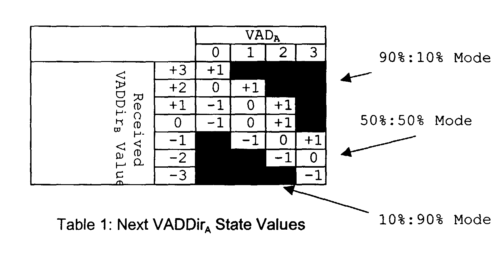
- Table 1 shows state transitions for the first radio 2, in dependence on the values of VADDir 1 which it derives from its own VAD value, and the value VADDir 1 of VADDir received from the second radio 4.
- This table shows each of the seven possible values of VADDir from -3 to +3 which the radio can receive. Each of these values occupies the first cell of one of the rows.
- the four possible values of VAD 1 from 0 to +3 are shown along the top of the table, each at the head of a column.
- the entries in the table show the new value of VADDir 1 , which would result from the received VADDir 2 shown at the left of the row, and the VAD 1 value shown at the top of the column.
- the shaded area at the upper right of the table indicates the new values of VADDir 1 which would cause the radio to operate in the 90%:10% mode.
- the shaded area at the lower left of the table indicates the new values of VADDir 1 which would cause the radio to operate in the 10%:90% mode.
- VADDir 1 values between +1 and -1. These are the new values of VADDir 1 which would cause the radio to operate in the 50%:50% mode.
- table one illustrates one practical example of an algorithm allowing values of VADDir sent from one radio to the other to control the proportion of the time for which each radio transmits and receives on the single radio channel.
- the first radio 2 When the first radio 2 has calculated a value for VADDir A , the first radio then transmits this value to the second radio 4.
- the second radio 4 uses its algorithm, that explained as 'Party B' above, to update its value of VADDir using the value of VADDir 1 received.
- the second radio 4 then has an updated value VADDir 2 of VADDir which it transmits back to first radio 2. This cycle repeats.
- Figure 4 shows three frame structures which could be used for communication between two digital radios.
- the frame shown as the upper trace in figure 4 shows roughly 80-90% of the transmission time being available to radio A, with roughly 10-20% of the transmission time available to radio B.
- the frame shown as the middle trace of figure 4 shows radio A and radio B each having roughly 50% of the transmission time.
- the frame shown as the lower trace in figure 4 shows roughly 10-20% of the transmission time being available to radio A, with roughly 80-90% of the transmission time available to radio B.
- radio A transmits before radio B in each of the three frame formats.
- the arrangement of figure 4 is such that radio A has full control of the transmission link between radios A and B. This means that the choice of frame structure, the synchronisation and timing are all under the control of radio A.
- radio B cannot interrupt the transmission by radio A. Radio B has to wait for the end of radio A's long transmission slot, before radio B can request more transmission time. If A grants the request, the system may move to the 50%:50% transmission time distribution shown in the middle trace on figure 4, but will only do this at the start of the next transmission frame at the earliest.
- Radio A may hear the start of radio B's speech with heavy clipping.
- the present invention alleviates the problem associated with radio communication arrangements having the frame formats and control structure illustrated by figure 4.
- a digital radio 2 for pseudo-duplex radio communication in accordance with the invention comprises:
- the controller 20 can unilaterally change the particular one of the plurality of pre-defined frame formats selected for use over the communication link. If the digital radio 2 is communicating with a first frame format, then the controller 20 can change this to a second frame format, the second frame format having a higher time division transmitting duty cycle for the digital radio 2 than the first frame format. Importantly, digital radio 2 can do this without consulting the second digital radio 4. This gives the digital radio 2 the ability to act swiftly to change the particular one of the plurality of pre-defined frame formats selected.
- Such a change may then be made by the digital radio 2 in response to the user of the digital radio 2 starting to speak, and the VAD value for the radio increasing.
- the swift response by digital radio 2 minimises loss of the user's speech.
- the second radio 4 will then perceive reduced clipping in comparison to prior art radio arrangements.
- the radio of the invention clearly differs from a radio operating with the frame structure shown in figure 4.
- radio 2 has control of the amount of transmission time available to it, even when it is transmitting for less time per frame than the second radio 4.
- the invention therefore separates control of the communication link from control of the transmission duty cycle.
- the radio of the invention will always have control over the transmission duty cycle when it is transmitting for less time than a radio with which it is in communication.
- the radio of the invention can then decide to use a greater proportion of each frame for transmission, by selecting a second, more advantageous frame structure, without having to await authority from the radio with which it is in communication.
- the invention has separated control of the communication link from control of the transmission duty cycle.
- first and a second radio in accordance with the invention in communication over a single radio channel.
- the radio which initiates the call may, for example, retain control of the channel for such matters as synchronisation throughout the duration of the call.
- the power to increase the proportion of time for transmission will always be vested in the radio which currently has the smaller proportion of the transmission time on the channel. This will be either the first or the second radio, depending on which is currently transmitting for less time than the other radio.
- the digital radio of the invention may have further features.
- the controller 20 may select a first frame format having time reserved in the first part of the frame for the digital radio 2 to transmit, and time reserved in the second part of the frame for the second digital radio 4 to transmit.
- a frame format is illustrated in the upper trace in figure 5. Figure 5 will be described in more detail below.
- the digital radio of the invention may select a second frame format comprising at least two time slots for the first digital radio 2 to transmit, and at least two time slots for the second digital radio 4 to transmit within each frame, the time slots for the first 2 and second 4 digital radios alternating within the frame.
- a frame structure is illustrated in the upper and lower traces at the centre and left of figure 6. Figure 6 will be described in more detail below.
- the advantage of the alternating time slots of figure 6, is that the digital radio 2 and the digital radio 4 alternate transmission within the frame, each transmission slot being shorter than that shown in the middle trace on figure 4 for an equivalent length of frame.
- radio 2 wishes to increase further the proportion of time available to it to transmit, it can initiate this during either of the transmission slots which it has during the alternation shown to the left of figure 6. Therefore the maximum time delay before the radio 2 can unilaterally seize extra transmission time amounts to the short time for which radio B is transmitting in the frame format of figure 6, left side.
- the second radio 4 can seize extra transmission time at any point during its two transmission slots in the frame.
- the digital radio 2 of the invention may select a second frame format having the time slots for the first digital radio 2 to transmit preceding the time slots for the second digital radio 4 to transmit. This is illustrated in figure 5, see trace T1.
- the digital radio 2 of the invention may select a first frame format which comprises less transmission time for the first digital radio 2 than for the second digital radio 4, and a second frame format which comprises substantially equal transmission times for the first digital radio 2 and for the second digital radio 4.
- first frame format may have substantially 20% transmission time for the first radio 2 and substantially 80% transmission time for the second radio 4.
- digital radio 2 for pseudo-duplex radio communication, digital radio 2 comprises:
- the radio 2 is designed to make a transition from the alternating 50%:50% transmission duty cycle to a frame format having a higher transmission duty cycle for the radio 2.
- the traces to the upper and lower left of figure 6 show frame formats with a 50%:50% transmission duty cycle, examples of the 'second' frame format.
- the radio 2 may start in a state where it is transmitting with the frame format shown at the upper left of figure 6, see trace T1.
- the radio 2 (shown as A) transmits in two time slots per frame. These are the first and third time slots, and each precedes a time slot reserved for the second radio 4 (shown as B).
- the radio 2 can move to a state where it is transmitting for more than 50% of the time. This is shown in figure 6, in the upper half of the right side of the figure.
- the digital radio 2 of the invention may have the controller 20 further adapted to derive the value of a source signal activity parameter (VAD) for the digital radio 2 using a soft voice-activity detector, the soft voice-activity detector providing a 2 bit output taking values from 0-3, where 0 represents silence with high confidence and 3 represents active speech with high confidence.
- VAD source signal activity parameter
- the digital radio 2 of the invention may be a digital portable or mobile radio, and the single radio channel may link the digital radio 2 to the second digital radio 4 via a base station 8. Alternatively however, the single radio channel may be a direct mode radio channel linking the digital radio 2 and the second digital radio 4.
- the digital radio 2 of the invention may be a digital portable or mobile radio operating in accordance with the DIIS radio standard.
- the invention further comprises a digital portable- or mobile radio system, comprising at least two radios as described above.
- party A is in control of the link and sets the synchronisation etc.
- party A is also in control of the duty cycle. This is in accordance with the invention, because party A is transmitting for the smaller proportion of the frame.
- party B is in control of the duty cycle.
- party A has allowed party B to transmit first, and has ceded control of the duty cycle to party B. This is in accordance with the invention, because party B is transmitting for the smaller proportion of the frame.
- Trace T1 on figure 6 arises when a radio operating with the frame structure of trace T1 of figure 5 changes mode to a frame in which both radios have 50% of the transmission time.
- trace T1 in figure 6 shows that party A transmits first in the frame, as was the case for trace T1 in figure 5.
- Trace T2 on figure 6 arises when a radio operating with the frame structure of trace T2 of figure 5 changes mode to a frame in which both radios have 50% of the transmission time.
- trace T2 in figure 6 shows that party B transmits first in the frame, as was the case for trace T2 in figure 5.
- either radio can change the duty cycle to give itself more transmission time, when the radios' start condition is the frame structure shown in either of traces T1 and T2.
- a radio can make this change during the slot when it is transmitting. Looking for example at trace T1 on figure 6, radio A has two time slots in each frame during which it could change the frame format to one which gave it more transmission time. These are the first and third time slots. If the frames shown in figures 5 and 6 are each 180 ms long, then radio A has substantially 45ms at the start of the frame where it can decide to increase its transmission time, and also substantially 45 ms more, occurring immediately after 90ms of the frame have elapsed.
- the right edge of figure 6 shows various frame structures which the radio of the invention may select if it starts from the frame structures on the left of figure 6, and increases the proportion of time in which it transmits.
- the upper three traces on the right of figure 6 may result for a radio initially operating according to trace T1 on figure 6, which moves to increase the proportion of time for which it transmits.
- the lower three traces on the right of figure 6 may result for a radio initially operating according to trace T2 on figure 6, which moves to increase the proportion of time for which it transmits.
- the frame formats in accordance with various embodiments of the invention shown in figures 5 and 6 may be 180 ms frames.
- the invention permits a rapid onset response, which may undercut the 64ms time after which speech clipping may become noticeable.
- the digital radio 2 illustrated in figure 2 performs an inventive method.
- One embodiment of the pseudo-duplex digital radio communication method of the invention comprises:
- Another embodiment of the pseudo-duplex digital radio communication method of the invention comprises:
- These techniques may serve to prevent loss of important parts of a user's speech as the user starts to talk into a radio.
Landscapes
- Engineering & Computer Science (AREA)
- Signal Processing (AREA)
- Computer Networks & Wireless Communication (AREA)
- Mobile Radio Communication Systems (AREA)
- Input Circuits Of Receivers And Coupling Of Receivers And Audio Equipment (AREA)
- Table Devices Or Equipment (AREA)
- Holo Graphy (AREA)
- Time-Division Multiplex Systems (AREA)
- Bidirectional Digital Transmission (AREA)
- Transceivers (AREA)
Abstract
Description
Claims (16)
- A digital radio (2) for pseudo-duplex radio communication, comprising:signal transmission means (22, 24) for time division duplex signal transmission over a single radio channel;signal reception means (24, 28) for time division duplex signal reception over the said single radio channel;a controller (20), for controlling the signal transmission means (22, 24) and the signal reception means (24, 28), the controller being adapted to transmit and receive signals in a plurality of pre-defined frame formats, each pre-defined frame format having a pre-defined time division duplex duty cycle, the controller being adapted to select the particular one of the plurality of pre-defined frame formats for use over the communication link;
wherein, with the digital radio (2) in communication over the said single radio channel with a second digital radio (4) and the digital radio (2) transmitting at a lower time division duplex duty cycle than the second digital radio (4),the controller (20) can unilaterally change the particular one of the plurality of pre-defined frame formats selected for use over the communication link from a first frame format to a second frame format, the second frame format having a higher time division transmitting duty cycle for the digital radio (2) than the first frame format, without consulting the second digital radio (4). - A digital radio (2) in accordance with claim 1, whereinwith the digital radio (2) in communication over the said single radio channel with a second digital radio (4) and the digital radio (2) transmitting at a lower time division duplex duty cycle than the second digital radio (4),the controller (20) is adapted to select a first frame format having time reserved in the first part of the frame for the digital radio (2) to transmit, and time reserved in the second part of the frame for the second digital radio (4) to transmit.
- A digital radio (2) in accordance with claim I or claim 2, whereinthe second frame format comprises at least two time slots for the first (2) digital radio to transmit and at least two time slots for the second (4) digital radio to transmit within each frame, the time slots for the first (2) and second (4) digital radios alternating within the frame.
- A digital radio (2) in accordance with claim 3, whereinthe second frame format further comprises the time slots for the first digital radio (2) to transmit preceding the time slots for the second digital radio (4) to transmit.
- A digital radio (2) in accordance with any previous claim, whereinthe first frame format comprises less transmission time for the first digital radio (2) than for the second digital radio (4), andthe second frame format comprises substantially equal transmission times for the first digital radio (2) and for the second digital radio (4).
- A digital radio (2) in accordance with any previous claim, whereinwith the digital radio (2) in communication over the said single radio channel with a second digital radio (4) and the digital radio (2) transmitting with a lower time division duplex duty cycle than the second digital radio (4),the controller (20) is adapted to change the selection from the current, first pre-defined frame format to a different, second pre-defined frame format, if the digital radio (2) detects source signal (VAD) for transmission.
- A digital radio (2) in accordance with any previous claim, whereinthe controller (20) is further adapted to select a first pre-defined frame format having substantially 20% transmission time for the first radio (2) and substantially 80% transmission time for the second radio (4).
- A digital radio (2) for pseudo-duplex radio communication, comprising:(i) signal transmission means (22, 24) for time division duplex signal transmission over a single radio channel;(ii) signal reception means (24, 28) for time division duplex signal reception over the said single radio channel;(iii) a controller (20), for controlling the signal transmission means (22, 24) and the signal reception means (24, 28), the controller being adapted to transmit and receive signals in a plurality of pre-defined frame formats, each pre-defined frame format having a pre-defined time division duplex duty cycle, the controller being adapted to select the particular one of the plurality of pre-defined frame formats for use over the communication link;(iv) wherein, with the digital radio (2) using a second frame format for communication over the said single radio channel with a second digital radio (4), the second frame format comprising substantially equal time for transmission by both the first digital radio (2) and the second digital radio (4), each frame of the second frame format having at least two time slots for the first digital radio (2) to transmit and at least two time slots for the second digital radio (4) to transmit, the time slots for the first (2) and second (4) radios alternating within the frame,during the time slots of the second frame for the first radio (2) to transmit, the controller (20) of the first radio (2) can unilaterally change the pre-defined frame format selected, from the second frame format to a third frame format, without consulting the second digital radio (4), the third frame format having a higher time division transmitting duty cycle for the first digital radio (2) than the second frame format.
- A digital radio (2) in accordance with any previous claim, whereinthe controller (20) is further adapted to derive the value of a source signal activity parameter (VAD) for the digital radio (2) using a soft voice-activity detector, the soft voice-activity detector providing a 2 bit output taking values from 0-3, where 0 represents silence with high confidence and 3 represents active speech with high confidence.
- A digital radio (2) in accordance with any previous claim, wherein the radio (2) is a digital portable or mobile radio, and the single radio channel links the digital radio (2) to the second digital radio (4) via a base station (8).
- A digital radio (2) in accordance any of claims 1-9, wherein the digital radio (2) is a digital portable or mobile radio, and the single radio channel is a direct mode radio channel linking the digital radio (2) and the second digital radio (4).
- A digital radio (2) in accordance with any previous claim, wherein the digital radio (2) is a digital portable or mobile radio operating in accordance with the DIIS radio standard.
- A digital radio (2) for pseudo-duplex radio communication substantially as hereinbefore described with reference to, or as illustrated by, any of figures 2, 3, 5 or 6 of the drawings.
- A digital portable- or mobile radio system, comprising at least two radios in accordance with any previous claim.
- A method of pseudo-duplex digital radio communication, comprising:transmitting a time division duplex signal over a single radio channel;receiving a time division duplex signal over the said single radio channel;selecting a particular one of a plurality of pre-defined frame formats for use over the single radio channel, each pre-defined frame format having a pre-defined time division duplex duty cycle;when the digital radio (2) is in communication over the said single radio channel with a second digital radio (4) and the digital radio (2) is transmitting at a lower time division duplex duty cycle than the second digital radio (4),unilaterally changing the particular one of the plurality of pre-defined frame formats selected for use over the single radio channel from a first frame format to a second frame format, the second frame format having a higher time division transmitting duty cycle for the digital radio (2) than the first frame format, without consultation with the second digital radio (4).
- A method of pseudo-duplex digital radio communication, comprising:(i) transmitting a time division duplex signal over a single radio channel;(ii) receiving a time division duplex signal over the said single radio channel;(iii) wherein the transmission and reception are between a first digital radio (2) and a second digital radio (4) and the transmission and reception are in a particular, second one of a plurality of pre-defined frame formats, each pre-defined frame format having a pre-defined time division duplex duty cycle, the second frame format comprising substantially equal time for transmission by both the first digital radio (2) and the second digital radio (4), each frame of the second frame format having at least two time slots for the first digital radio (2) to transmit and at least two time slots for the second digital radio (4) to transmit, the time slots for the first (2) and second (4) radios alternating within the frame;
and(iv) during the time slots of the second frame for the first radio (2) to transmit, the first radio (2) can unilaterally change the pre-defined frame format selected, from the second frame format to a third frame format, without consulting the second digital radio (4), the third frame format having a higher time division transmitting duty cycle for the first digital radio (2) than the second frame format.
Applications Claiming Priority (2)
| Application Number | Priority Date | Filing Date | Title |
|---|---|---|---|
| GB9915280A GB2351877B (en) | 1999-06-30 | 1999-06-30 | Digital radio for pseudo-duplex radio communication |
| GB9915280 | 1999-06-30 |
Publications (3)
| Publication Number | Publication Date |
|---|---|
| EP1065808A2 true EP1065808A2 (en) | 2001-01-03 |
| EP1065808A3 EP1065808A3 (en) | 2003-10-01 |
| EP1065808B1 EP1065808B1 (en) | 2006-01-11 |
Family
ID=10856343
Family Applications (1)
| Application Number | Title | Priority Date | Filing Date |
|---|---|---|---|
| EP00110611A Expired - Lifetime EP1065808B1 (en) | 1999-06-30 | 2000-05-18 | Digital radio |
Country Status (5)
| Country | Link |
|---|---|
| US (1) | US6724735B1 (en) |
| EP (1) | EP1065808B1 (en) |
| AT (1) | ATE315852T1 (en) |
| DE (1) | DE60025410T2 (en) |
| GB (1) | GB2351877B (en) |
Cited By (2)
| Publication number | Priority date | Publication date | Assignee | Title |
|---|---|---|---|---|
| EP1575190A1 (en) * | 2004-03-12 | 2005-09-14 | Motorola, Inc. | Dynamically setting and changing a TDMA slotting structure to accomodate different call types |
| US8411602B2 (en) * | 2008-05-01 | 2013-04-02 | Fujitsu Limited | Radio communication apparatus |
Families Citing this family (5)
| Publication number | Priority date | Publication date | Assignee | Title |
|---|---|---|---|---|
| GB2351876B (en) * | 1999-06-29 | 2003-06-04 | Motorola Ltd | Digital radio |
| US20080268802A1 (en) * | 2005-08-04 | 2008-10-30 | International Business Machines Corporation | Radio receiver that changes function according to the output of an internal voice-only detector |
| US20090046701A1 (en) * | 2006-01-13 | 2009-02-19 | Matsushita Electric Industrial Co., Ltd. | Radio communication base station apparatus and synchronization channel signal transmission method |
| US20090059854A1 (en) * | 2006-01-13 | 2009-03-05 | Matsaushita Electric Industrial Co., Ltd. | Radio communication base station apparatus and radio communication method |
| US8982744B2 (en) * | 2007-06-06 | 2015-03-17 | Broadcom Corporation | Method and system for a subband acoustic echo canceller with integrated voice activity detection |
Family Cites Families (13)
| Publication number | Priority date | Publication date | Assignee | Title |
|---|---|---|---|---|
| GB8418935D0 (en) * | 1984-07-25 | 1984-08-30 | Racal Res Ltd | Duplex communications |
| US4980886A (en) * | 1988-11-03 | 1990-12-25 | Sprint International Communications Corporation | Communication system utilizing dynamically slotted information |
| US4949335A (en) * | 1989-01-23 | 1990-08-14 | Motorola, Inc. | A TDM quasi-duplex system |
| US5511073A (en) * | 1990-06-25 | 1996-04-23 | Qualcomm Incorporated | Method and apparatus for the formatting of data for transmission |
| US5379279A (en) * | 1993-07-06 | 1995-01-03 | Motorola, Inc. | Communication device with time assigned duplex operation |
| US5602836A (en) * | 1993-11-24 | 1997-02-11 | Lucent Technologies Inc. | Multiple access cellular communication with circular interleaving and reduced dropped-packet runlengths |
| FI103700B (en) * | 1994-09-20 | 1999-08-13 | Nokia Mobile Phones Ltd | Simultaneous transmission of voice and data in mobile telecommunication systems |
| US5802046A (en) * | 1995-06-05 | 1998-09-01 | Omnipoint Corporation | Efficient time division duplex communication system with interleaved format and timing adjustment control |
| US6175738B1 (en) * | 1996-04-04 | 2001-01-16 | Siemens Aktiengesellschaft | Assigning channels of different capacities in a hybrid ISDN-DECT telecommunications system |
| JPH10285148A (en) * | 1997-04-04 | 1998-10-23 | Matsushita Electric Ind Co Ltd | Wireless communication device and cellular system |
| US6393007B1 (en) * | 1997-10-16 | 2002-05-21 | Telefonaktiebolaget Lm Ericsson (Publ) | Method of and a system for voice and data radio communication providing improved interference diversity |
| US6088337A (en) * | 1997-10-20 | 2000-07-11 | Motorola, Inc. | Method access point device and peripheral for providing space diversity in a time division duplex wireless system |
| US6496706B1 (en) * | 1999-07-23 | 2002-12-17 | Qualcomm Incorporated | Method and system for transmit gating in a wireless communication system |
-
1999
- 1999-06-30 GB GB9915280A patent/GB2351877B/en not_active Expired - Fee Related
-
2000
- 2000-02-02 US US09/497,020 patent/US6724735B1/en not_active Expired - Fee Related
- 2000-05-18 EP EP00110611A patent/EP1065808B1/en not_active Expired - Lifetime
- 2000-05-18 AT AT00110611T patent/ATE315852T1/en not_active IP Right Cessation
- 2000-05-18 DE DE60025410T patent/DE60025410T2/en not_active Expired - Lifetime
Cited By (2)
| Publication number | Priority date | Publication date | Assignee | Title |
|---|---|---|---|---|
| EP1575190A1 (en) * | 2004-03-12 | 2005-09-14 | Motorola, Inc. | Dynamically setting and changing a TDMA slotting structure to accomodate different call types |
| US8411602B2 (en) * | 2008-05-01 | 2013-04-02 | Fujitsu Limited | Radio communication apparatus |
Also Published As
| Publication number | Publication date |
|---|---|
| EP1065808A3 (en) | 2003-10-01 |
| US6724735B1 (en) | 2004-04-20 |
| ATE315852T1 (en) | 2006-02-15 |
| GB2351877A (en) | 2001-01-10 |
| GB2351877B (en) | 2003-08-20 |
| EP1065808B1 (en) | 2006-01-11 |
| DE60025410D1 (en) | 2006-04-06 |
| GB9915280D0 (en) | 1999-09-01 |
| DE60025410T2 (en) | 2006-07-27 |
Similar Documents
| Publication | Publication Date | Title |
|---|---|---|
| US5799250A (en) | Interface arrangement for connecting base stations to a private branch exchange | |
| JP2679442B2 (en) | Digital mobile communication system | |
| KR950000359B1 (en) | Radio communications system | |
| CA1231788A (en) | Duplex speech transmission method and a system therefor | |
| US8213343B2 (en) | Communicating conversational data between signals between terminals | |
| JPH08130775A (en) | Digital cordless telephone system | |
| US5594737A (en) | Arrangement for controlling a transmitting/receiving device of base stations and/or mobile units, in particular of a cordless telephone system | |
| KR950000360B1 (en) | Radio communications system | |
| EP1732346B1 (en) | Apparatus and method for sharing a unique identifier among a plurality of receivers | |
| EP1065808B1 (en) | Digital radio | |
| US7574229B2 (en) | Output power control in multislot uplinks | |
| CN1930809B (en) | Method of TDMA system | |
| US6970442B1 (en) | Multiple-access scheme for packet voice that uses voice activity detection | |
| US5712848A (en) | Time division multiplex communications system including means for reducing undesired echoes resulting from circuit delays | |
| US6172965B1 (en) | Duplex transmission scheme | |
| EP0169713A2 (en) | Duplex communications | |
| US6847627B1 (en) | Time-division multiple access (TDMA) multi-line wireless telephone system | |
| US6898191B1 (en) | Digital radio | |
| JPS6248137A (en) | Radiotelephoney system | |
| EP1338163A1 (en) | Method for allocating radio resources to mobile stations, telecommunications network and mobile station | |
| KR100561930B1 (en) | Time-division multiple access (TGD) multi-line wireless telephone system, communication method and wireless handset | |
| JPH11261519A (en) | Communication method and communication device for wireless local loop system | |
| JP3186849B2 (en) | Modification information transmission method of information channel | |
| KR100430594B1 (en) | Method for controlling operation of mobile terminal capable of high data rate service | |
| WO2008027743A2 (en) | System for combining uplink data blocks from a user with transmission pauses from another user |
Legal Events
| Date | Code | Title | Description |
|---|---|---|---|
| PUAI | Public reference made under article 153(3) epc to a published international application that has entered the european phase |
Free format text: ORIGINAL CODE: 0009012 |
|
| AK | Designated contracting states |
Kind code of ref document: A2 Designated state(s): AT BE CH CY DE DK ES FI FR GB GR IE IT LI LU MC NL PT SE |
|
| AX | Request for extension of the european patent |
Free format text: AL;LT;LV;MK;RO;SI |
|
| PUAL | Search report despatched |
Free format text: ORIGINAL CODE: 0009013 |
|
| AK | Designated contracting states |
Kind code of ref document: A3 Designated state(s): AT BE CH CY DE DK ES FI FR GB GR IE IT LI LU MC NL PT SE |
|
| AX | Request for extension of the european patent |
Extension state: AL LT LV MK RO SI |
|
| RIC1 | Information provided on ipc code assigned before grant |
Ipc: 7H 04L 5/14 B Ipc: 7H 04B 7/26 A |
|
| 17P | Request for examination filed |
Effective date: 20040401 |
|
| AKX | Designation fees paid |
Designated state(s): AT BE CH CY DE DK ES FI FR GB GR IE IT LI LU MC NL PT SE |
|
| 17Q | First examination report despatched |
Effective date: 20041029 |
|
| GRAP | Despatch of communication of intention to grant a patent |
Free format text: ORIGINAL CODE: EPIDOSNIGR1 |
|
| GRAS | Grant fee paid |
Free format text: ORIGINAL CODE: EPIDOSNIGR3 |
|
| GRAA | (expected) grant |
Free format text: ORIGINAL CODE: 0009210 |
|
| AK | Designated contracting states |
Kind code of ref document: B1 Designated state(s): AT BE CH CY DE DK ES FI FR GR IE IT LI LU MC NL PT SE |
|
| PG25 | Lapsed in a contracting state [announced via postgrant information from national office to epo] |
Ref country code: IT Free format text: LAPSE BECAUSE OF FAILURE TO SUBMIT A TRANSLATION OF THE DESCRIPTION OR TO PAY THE FEE WITHIN THE PRESCRIBED TIME-LIMIT;WARNING: LAPSES OF ITALIAN PATENTS WITH EFFECTIVE DATE BEFORE 2007 MAY HAVE OCCURRED AT ANY TIME BEFORE 2007. THE CORRECT EFFECTIVE DATE MAY BE DIFFERENT FROM THE ONE RECORDED. Effective date: 20060111 Ref country code: BE Free format text: LAPSE BECAUSE OF FAILURE TO SUBMIT A TRANSLATION OF THE DESCRIPTION OR TO PAY THE FEE WITHIN THE PRESCRIBED TIME-LIMIT Effective date: 20060111 Ref country code: LI Free format text: LAPSE BECAUSE OF FAILURE TO SUBMIT A TRANSLATION OF THE DESCRIPTION OR TO PAY THE FEE WITHIN THE PRESCRIBED TIME-LIMIT Effective date: 20060111 Ref country code: FI Free format text: LAPSE BECAUSE OF FAILURE TO SUBMIT A TRANSLATION OF THE DESCRIPTION OR TO PAY THE FEE WITHIN THE PRESCRIBED TIME-LIMIT Effective date: 20060111 Ref country code: NL Free format text: LAPSE BECAUSE OF FAILURE TO SUBMIT A TRANSLATION OF THE DESCRIPTION OR TO PAY THE FEE WITHIN THE PRESCRIBED TIME-LIMIT Effective date: 20060111 Ref country code: AT Free format text: LAPSE BECAUSE OF FAILURE TO SUBMIT A TRANSLATION OF THE DESCRIPTION OR TO PAY THE FEE WITHIN THE PRESCRIBED TIME-LIMIT Effective date: 20060111 Ref country code: CH Free format text: LAPSE BECAUSE OF FAILURE TO SUBMIT A TRANSLATION OF THE DESCRIPTION OR TO PAY THE FEE WITHIN THE PRESCRIBED TIME-LIMIT Effective date: 20060111 |
|
| REG | Reference to a national code |
Ref country code: CH Ref legal event code: EP |
|
| REG | Reference to a national code |
Ref country code: IE Ref legal event code: FG4D |
|
| REF | Corresponds to: |
Ref document number: 60025410 Country of ref document: DE Date of ref document: 20060406 Kind code of ref document: P |
|
| PG25 | Lapsed in a contracting state [announced via postgrant information from national office to epo] |
Ref country code: SE Free format text: LAPSE BECAUSE OF FAILURE TO SUBMIT A TRANSLATION OF THE DESCRIPTION OR TO PAY THE FEE WITHIN THE PRESCRIBED TIME-LIMIT Effective date: 20060411 Ref country code: DK Free format text: LAPSE BECAUSE OF FAILURE TO SUBMIT A TRANSLATION OF THE DESCRIPTION OR TO PAY THE FEE WITHIN THE PRESCRIBED TIME-LIMIT Effective date: 20060411 |
|
| PG25 | Lapsed in a contracting state [announced via postgrant information from national office to epo] |
Ref country code: ES Free format text: LAPSE BECAUSE OF FAILURE TO SUBMIT A TRANSLATION OF THE DESCRIPTION OR TO PAY THE FEE WITHIN THE PRESCRIBED TIME-LIMIT Effective date: 20060422 |
|
| PG25 | Lapsed in a contracting state [announced via postgrant information from national office to epo] |
Ref country code: IE Free format text: LAPSE BECAUSE OF NON-PAYMENT OF DUE FEES Effective date: 20060518 |
|
| PG25 | Lapsed in a contracting state [announced via postgrant information from national office to epo] |
Ref country code: MC Free format text: LAPSE BECAUSE OF NON-PAYMENT OF DUE FEES Effective date: 20060531 |
|
| PG25 | Lapsed in a contracting state [announced via postgrant information from national office to epo] |
Ref country code: PT Free format text: LAPSE BECAUSE OF FAILURE TO SUBMIT A TRANSLATION OF THE DESCRIPTION OR TO PAY THE FEE WITHIN THE PRESCRIBED TIME-LIMIT Effective date: 20060612 |
|
| NLV1 | Nl: lapsed or annulled due to failure to fulfill the requirements of art. 29p and 29m of the patents act | ||
| REG | Reference to a national code |
Ref country code: CH Ref legal event code: PL |
|
| ET | Fr: translation filed | ||
| PLBE | No opposition filed within time limit |
Free format text: ORIGINAL CODE: 0009261 |
|
| STAA | Information on the status of an ep patent application or granted ep patent |
Free format text: STATUS: NO OPPOSITION FILED WITHIN TIME LIMIT |
|
| 26N | No opposition filed |
Effective date: 20061012 |
|
| PG25 | Lapsed in a contracting state [announced via postgrant information from national office to epo] |
Ref country code: GR Free format text: LAPSE BECAUSE OF FAILURE TO SUBMIT A TRANSLATION OF THE DESCRIPTION OR TO PAY THE FEE WITHIN THE PRESCRIBED TIME-LIMIT Effective date: 20060412 |
|
| PG25 | Lapsed in a contracting state [announced via postgrant information from national office to epo] |
Ref country code: LU Free format text: LAPSE BECAUSE OF NON-PAYMENT OF DUE FEES Effective date: 20060518 |
|
| PG25 | Lapsed in a contracting state [announced via postgrant information from national office to epo] |
Ref country code: CY Free format text: LAPSE BECAUSE OF FAILURE TO SUBMIT A TRANSLATION OF THE DESCRIPTION OR TO PAY THE FEE WITHIN THE PRESCRIBED TIME-LIMIT Effective date: 20060111 |
|
| PGFP | Annual fee paid to national office [announced via postgrant information from national office to epo] |
Ref country code: FR Payment date: 20110511 Year of fee payment: 12 |
|
| PGFP | Annual fee paid to national office [announced via postgrant information from national office to epo] |
Ref country code: DE Payment date: 20110531 Year of fee payment: 12 |
|
| REG | Reference to a national code |
Ref country code: FR Ref legal event code: CD Owner name: MOTOTOLA SOLUTIONS UK LIMITED Effective date: 20111102 |
|
| REG | Reference to a national code |
Ref country code: DE Ref legal event code: R082 Ref document number: 60025410 Country of ref document: DE Representative=s name: SCHUMACHER & WILLSAU PATENTANWALTSGESELLSCHAFT, DE |
|
| REG | Reference to a national code |
Ref country code: DE Ref legal event code: R081 Ref document number: 60025410 Country of ref document: DE Owner name: MOTOROLA SOLUTIONS UK LIMITED, GB Free format text: FORMER OWNER: MOTOROLA LTD., BASINGSTOKE, GB Effective date: 20120117 Ref country code: DE Ref legal event code: R082 Ref document number: 60025410 Country of ref document: DE Representative=s name: SCHUMACHER & WILLSAU PATENTANWALTSGESELLSCHAFT, DE Effective date: 20120117 Ref country code: DE Ref legal event code: R081 Ref document number: 60025410 Country of ref document: DE Owner name: MOTOROLA SOLUTIONS UK LIMITED, BASINGSTOKE, GB Free format text: FORMER OWNER: MOTOROLA LTD., BASINGSTOKE, HAMPSHIRE, GB Effective date: 20120117 |
|
| REG | Reference to a national code |
Ref country code: FR Ref legal event code: ST Effective date: 20130131 |
|
| REG | Reference to a national code |
Ref country code: DE Ref legal event code: R119 Ref document number: 60025410 Country of ref document: DE Effective date: 20121201 |
|
| PG25 | Lapsed in a contracting state [announced via postgrant information from national office to epo] |
Ref country code: FR Free format text: LAPSE BECAUSE OF NON-PAYMENT OF DUE FEES Effective date: 20120531 |
|
| PG25 | Lapsed in a contracting state [announced via postgrant information from national office to epo] |
Ref country code: DE Free format text: LAPSE BECAUSE OF NON-PAYMENT OF DUE FEES Effective date: 20121201 |