EP1065764A2 - Apparatus for optically pumping an optical fiber from the side - Google Patents
Apparatus for optically pumping an optical fiber from the side Download PDFInfo
- Publication number
- EP1065764A2 EP1065764A2 EP00111944A EP00111944A EP1065764A2 EP 1065764 A2 EP1065764 A2 EP 1065764A2 EP 00111944 A EP00111944 A EP 00111944A EP 00111944 A EP00111944 A EP 00111944A EP 1065764 A2 EP1065764 A2 EP 1065764A2
- Authority
- EP
- European Patent Office
- Prior art keywords
- fiber
- grating
- optical fiber
- set forth
- angle
- Prior art date
- Legal status (The legal status is an assumption and is not a legal conclusion. Google has not performed a legal analysis and makes no representation as to the accuracy of the status listed.)
- Granted
Links
Images


Classifications
-
- G—PHYSICS
- G02—OPTICS
- G02B—OPTICAL ELEMENTS, SYSTEMS OR APPARATUS
- G02B6/00—Light guides; Structural details of arrangements comprising light guides and other optical elements, e.g. couplings
- G02B6/24—Coupling light guides
- G02B6/42—Coupling light guides with opto-electronic elements
- G02B6/4201—Packages, e.g. shape, construction, internal or external details
- G02B6/4204—Packages, e.g. shape, construction, internal or external details the coupling comprising intermediate optical elements, e.g. lenses, holograms
- G02B6/4214—Packages, e.g. shape, construction, internal or external details the coupling comprising intermediate optical elements, e.g. lenses, holograms the intermediate optical element having redirecting reflective means, e.g. mirrors, prisms for deflecting the radiation from horizontal to down- or upward direction toward a device
-
- G—PHYSICS
- G02—OPTICS
- G02B—OPTICAL ELEMENTS, SYSTEMS OR APPARATUS
- G02B6/00—Light guides; Structural details of arrangements comprising light guides and other optical elements, e.g. couplings
- G02B6/02—Optical fibres with cladding with or without a coating
- G02B6/02057—Optical fibres with cladding with or without a coating comprising gratings
- G02B6/02066—Gratings having a surface relief structure, e.g. repetitive variation in diameter of core or cladding
-
- G—PHYSICS
- G02—OPTICS
- G02B—OPTICAL ELEMENTS, SYSTEMS OR APPARATUS
- G02B6/00—Light guides; Structural details of arrangements comprising light guides and other optical elements, e.g. couplings
- G02B6/24—Coupling light guides
- G02B6/26—Optical coupling means
- G02B6/34—Optical coupling means utilising prism or grating
-
- H—ELECTRICITY
- H01—ELECTRIC ELEMENTS
- H01S—DEVICES USING THE PROCESS OF LIGHT AMPLIFICATION BY STIMULATED EMISSION OF RADIATION [LASER] TO AMPLIFY OR GENERATE LIGHT; DEVICES USING STIMULATED EMISSION OF ELECTROMAGNETIC RADIATION IN WAVE RANGES OTHER THAN OPTICAL
- H01S3/00—Lasers, i.e. devices using stimulated emission of electromagnetic radiation in the infrared, visible or ultraviolet wave range
- H01S3/09—Processes or apparatus for excitation, e.g. pumping
- H01S3/091—Processes or apparatus for excitation, e.g. pumping using optical pumping
- H01S3/094—Processes or apparatus for excitation, e.g. pumping using optical pumping by coherent light
- H01S3/094003—Processes or apparatus for excitation, e.g. pumping using optical pumping by coherent light the pumped medium being a fibre
-
- G—PHYSICS
- G02—OPTICS
- G02B—OPTICAL ELEMENTS, SYSTEMS OR APPARATUS
- G02B6/00—Light guides; Structural details of arrangements comprising light guides and other optical elements, e.g. couplings
- G02B6/02—Optical fibres with cladding with or without a coating
- G02B6/02057—Optical fibres with cladding with or without a coating comprising gratings
- G02B6/02061—Grating external to the fibre and in contact with the fibre, e.g. evanescently coupled, gratings applied to the fibre end
-
- G—PHYSICS
- G02—OPTICS
- G02B—OPTICAL ELEMENTS, SYSTEMS OR APPARATUS
- G02B6/00—Light guides; Structural details of arrangements comprising light guides and other optical elements, e.g. couplings
- G02B6/02—Optical fibres with cladding with or without a coating
- G02B6/02057—Optical fibres with cladding with or without a coating comprising gratings
- G02B6/02071—Mechanically induced gratings, e.g. having microbends
-
- G—PHYSICS
- G02—OPTICS
- G02B—OPTICAL ELEMENTS, SYSTEMS OR APPARATUS
- G02B6/00—Light guides; Structural details of arrangements comprising light guides and other optical elements, e.g. couplings
- G02B6/24—Coupling light guides
- G02B6/26—Optical coupling means
- G02B6/28—Optical coupling means having data bus means, i.e. plural waveguides interconnected and providing an inherently bidirectional system by mixing and splitting signals
- G02B6/2804—Optical coupling means having data bus means, i.e. plural waveguides interconnected and providing an inherently bidirectional system by mixing and splitting signals forming multipart couplers without wavelength selective elements, e.g. "T" couplers, star couplers
- G02B6/2852—Optical coupling means having data bus means, i.e. plural waveguides interconnected and providing an inherently bidirectional system by mixing and splitting signals forming multipart couplers without wavelength selective elements, e.g. "T" couplers, star couplers using tapping light guides arranged sidewardly, e.g. in a non-parallel relationship with respect to the bus light guides (light extraction or launching through cladding, with or without surface discontinuities, bent structures)
-
- H—ELECTRICITY
- H01—ELECTRIC ELEMENTS
- H01S—DEVICES USING THE PROCESS OF LIGHT AMPLIFICATION BY STIMULATED EMISSION OF RADIATION [LASER] TO AMPLIFY OR GENERATE LIGHT; DEVICES USING STIMULATED EMISSION OF ELECTROMAGNETIC RADIATION IN WAVE RANGES OTHER THAN OPTICAL
- H01S3/00—Lasers, i.e. devices using stimulated emission of electromagnetic radiation in the infrared, visible or ultraviolet wave range
- H01S3/05—Construction or shape of optical resonators; Accommodation of active medium therein; Shape of active medium
- H01S3/06—Construction or shape of active medium
- H01S3/063—Waveguide lasers, i.e. whereby the dimensions of the waveguide are of the order of the light wavelength
- H01S3/067—Fibre lasers
- H01S3/06754—Fibre amplifiers
-
- H—ELECTRICITY
- H01—ELECTRIC ELEMENTS
- H01S—DEVICES USING THE PROCESS OF LIGHT AMPLIFICATION BY STIMULATED EMISSION OF RADIATION [LASER] TO AMPLIFY OR GENERATE LIGHT; DEVICES USING STIMULATED EMISSION OF ELECTROMAGNETIC RADIATION IN WAVE RANGES OTHER THAN OPTICAL
- H01S3/00—Lasers, i.e. devices using stimulated emission of electromagnetic radiation in the infrared, visible or ultraviolet wave range
- H01S3/09—Processes or apparatus for excitation, e.g. pumping
- H01S3/091—Processes or apparatus for excitation, e.g. pumping using optical pumping
- H01S3/094—Processes or apparatus for excitation, e.g. pumping using optical pumping by coherent light
- H01S3/094003—Processes or apparatus for excitation, e.g. pumping using optical pumping by coherent light the pumped medium being a fibre
- H01S3/094019—Side pumped fibre, whereby pump light is coupled laterally into the fibre via an optical component like a prism, or a grating, or via V-groove coupling
Definitions
- the present invention relates generally to an apparatus for side pumping an optical fiber, and, more particularly, to an apparatus for optically pumping an optical fiber from the side that comprises a grating formed on a multimode fiber.
- Fiber amplifiers and fiber lasers require high optical pump levels to be injected within the region of the fiber that includes the active medium that provides the optical gain.
- the output power from fiber amplifiers and fiber lasers is limited by the amount of optical power that can be injected into the active medium of the fiber. This limitation stems from the approaches that have been used in the past to couple optical pump power into the fiber.
- wavelength division multiplexing (WDM) couplers are typically used. This requires that the path of the doped fiber be interrupted to provide for a section of fiber to connect to the WDM coupler. Such an interruption complicates the pumping process.
- WDM wavelength division multiplexing
- end pumping provides at most only two input ends through which all the injected optical pump power enters the fiber. This physically constrains the number and type of pump sources that are able to be used to inject the optical power. Such a constraint has led to the development of optical side pumping techniques for dual clad doped fiber in which the entire length of the fiber is made available to couple in a much greater number and type of optical pump sources.
- WDM allows pump light having a different wavelength from that which is to be amplified to be coupled into the doped fiber at any point along the fiber provided that an interruption is made for the WDM coupler in the doped fiber.
- the WDM coupler is designed so that pump light is sent into one of the two input fibers and the light to be amplified is sent into the other input fiber.
- the interaction length between the two closely coupled fibers is precisely selected to enable the pump light to be completely coupled to the fiber with the light to be amplified while the light to be amplified remains in the same fiber. This is relatively complex.
- a second method for side coupling pump light is to cut V-grooves into the cladding of dual clad doped fiber.
- the V-grooves bounce the side-coupled light into a mode of propagation along the fiber.
- the cutting of the V-grooves generally weakens the fiber.
- a third approach for side pumping is to couple light through a prism into a dual clad doped fiber by precisely locating the prism against an exposed cladding interface. This exact positioning, however, is difficult to achieve.
- gratings have been employed in doped fibers to Bragg diffract the propagating light either back onto itself or to couple the propagating light out of the fiber. But a grating had not been used to couple optical pump light into a fiber to enable amplification or laser action on light at another wavelength.
- the apparatus comprises a laser for supplying a beam of pump light, an optical fiber, and a grating to allow diffractive coupling of the pump fight into the fiber.
- the optical fiber includes a multimode fiber having a longitudinal surface disposed in the beam of the pump light with at least one propagating mode characterized by a propagation angle.
- the grating is formed on the longitudinal surface for diffracting the beam of pump light at a predetermined angle that matches the propagation angle.
- the apparatus 10 includes a laser pump source 12 for providing a beam of pump light.
- the laser pump source 12 is a semiconductor laser diode bar that provides an optical beam having a small range of a wavelengths centered around the absorption peak of the optical gain media to be pumped.
- other pump sources such as a multi transverse mode wide stripe laser diode or a multimode fiber pigtailed laser diode which delivers light from the output of a multimode fiber may be utilized. As will be described, this range of wavelengths will excite the dopant in the central core of an optical fiber and provide optical gain for either optical amplification or laser action.
- a lens 13 serves to collimate the pump light beam, generally illustrated by the numeral 14.
- an optical fiber is disposed in the path of the beam 14 and includes a central core 18, a multimode fiber 20 and an outer cladding layer 22 that surrounds the fiber 20.
- the outer cladding layer 22 is removed in the region proximate the pump beam 14. In such region the surrounding air provides the dielectric interface required for multimode guiding. Thus, in the region in the path of the beam 14 there is no outer layer around the multimode fiber 20.
- the central core 18 comprises a rare earth dopant or dopants that can be optically excited by the pump light to provide optical gain for light confined to the core.
- pump light propagating in the multimode region surrounding the core will interact with the doped core region to optically excite this gain media to enable amplification of the fight confined to the core.
- the central core is co-doped with Ytterbium/Erbium and is pumped with a wavelength approximating 917nm. As is well known, this wavelength excites the Ytterbium in the core which then transfers its energy to Erbium to provide an output optical gain at 1.55 ⁇ m.
- the multimode fiber 20 is an elongated element that is characterized by an index of refraction n 2 and has a generally rectangular shape in cross-section (see FIG. 2) with a longitudinal segment 23 having flat opposed longitudinal surfaces 26 and 28.
- the index of refraction and cross section dimensions support at lease one propagating mode characterized by a propagation angle and can support many additional modes with additional unique propagation angles.
- the multimode fiber is a dual clad fiber manufactured by INO, of Canada, and having an index of refraction of approximately 1.45. As illustrated, its longitudinal flat surfaces 26 and 28 are disposed in the path of the pump beam 14.
- a grating 34 is formed on the surface 26 and extends into the multimode fiber 20 (or subjacent the surface as shown in FIG. 4 or inside the fiber as shown in FIG. 8, both as will be described subsequently), and serves to Bragg diffract the pump beam 14.
- the grating 34 has a periodic sawtooth shape in front view (see FIG. 3) that provides a blazed corrugated relief pattern that is optimized for most efficient diffraction of the pump light wavelength at the angle that matches the propagation modes of the multimode fiber. By using a blazed, sawtooth grating profile, the grating 34 is more efficient in directing light into a particular diffraction order relative to other diffraction orders.
- the grating period ⁇ i.e.
- the dimension of one sawtooth is selected so that the diffraction angle matches the propagation mode of the multimode optical fiber 16.
- the period ⁇ is selected such that only one diffraction angle occurs and this angle matches the propagating mode of the multimode fiber 20.
- the particular period dimensions determines the angle and direction that the pump beam is Bragg diffracted and the blazing of the corrugated relief pattern determines the efficiency with which this diffraction takes place.
- the grating 34 is coated with a thin layer of reflective material 36, such as a metal, e.g. chrome, gold, silver, or aluminum. This reflective layer 36 increases the diffraction efficiency of the grating.
- the diffracted light is diffracted in a direction that places it on the same side as laser 12.
- the incidence angle ⁇ or 50 is a slight angle off normal incidence.
- the laser pump source 12 generates the pump laser beam 14.
- the spectral spread of the pump laser beam creates several diffraction angles with each angle in the prescribed range corresponding to a propagating mode of the multimode fiber 20.
- the fact that there are many closely spaced angles that match to propagating modes of the multimode fiber is an advantage of the present invention in that the pump light is not required to be diffracted at only one angle in order to be successfully launched into a propagating mode. This condition is particularly helpful because the pump light is preferably produced from the laser diode bar which operates on a small range of wavelengths instead of merely producing a single wavelength. This small range of pump wavelengths diffracts off the grating 34 at slightly different angles and thus utilizes the small range of angles that can match to propagating modes in the multimode fiber 20.
- the multimode region of the fiber has an effective refractive index of approximately 1.45 and supports many modes of propagation at the pump wavelength. It is approximately 100 ⁇ m in thickness.
- the various modes supported by the multimode fiber allows the grating period to couple in a wavelength span of ⁇ 2nm ranging around the pump wavelength, which accommodates a typical spectral response of pump lasers.
- the incident pump light 14 approaches the surface 26 at an angle smaller than 90° and is Bragg diffracted at the angle ⁇ along the path 52 in a direction toward the surface 28 at its boundary with the outer cladding layer 22. All such angles are within the total internal reflection condition for the interface between the multimode fiber 20 and the outer cladding 22 (or the air in the region where the outer cladding layer 22 has been removed).
- the pump light matching the propagating mode in the multimode fiber 20 is conveyed to the region under the outer cladding layer 22 and continues to propagate down the remainder of the optical fiber 20.
- the light propagation paths 52 run generally parallel to the longitudinal direction of the optical fiber. This allows the reflected and confined paths to bounce within the multimode fiber 20 as the light propagates into the region surrounded by the outer cladding layer 22.
- This propagating pump light interacts with the rare earth dopant in the core 18 and optically excites this dopant to provide optical gain.
- This excited dopant serves to optically amplify light that is confined to propagation just in the central core 18, in a manner well known in the art.
- the amplified light can be used to provide a fiber laser or a fiber amplifier, generally illustrated by the numeral 40 in FIG. 1.
- the grating is formed on the surface 28 and into the fiber closest to the pump laser source 12.
- a metal reflecting layer 36 is not employed so that the pump beam is not shielded and thus is able to be diffracted by the grating formed by the periodic relief pattern which creates a periodic variation in the refractive index.
- the cross section of the multimode fiber 20 is D-shaped. Other shapes are also possible as long as the longitudinal surface 26 of the fiber is ground flat to allow the grating relief pattern to be applied.
- FIGs. 4 and 5 another alternative embodiment of the apparatus 70 for optically pumping an optical fiber from the side employs a commercially-available metallized blazed grating 35.
- Commercial gratings are generally wider than the cross section dimension of an optical fiber, and thus will extend out beyond the fiber as shown in FIG. 5.
- Many of the elements of the apparatus 70 are identical in construction to like elements in the apparatus 10 illustrated in FIG. 1, described above, and accordingly, there have been applied to each element of the apparatus 70 a reference numeral corresponding to the reference numeral that was applied to like elements of the apparatus 10.
- the grating 35 comprises a substrate, e.g.
- This grating coupler functions in exactly the same manner as described relative to the apparatus shown in FIG. 1. As described, the diffracted pump light 52 matches the propagating mode of the multimode fiber 20.
- the grating can be formed on the surface and into the fiber (FIG. 1) or on, subjacent or adjacent the surface (FIG. 4) or in the fiber (FIG. 8). Functionally, the grating serves the same purpose. Accordingly, the words “on” or “in” are interchangeable in meaning. For consistency, hereafter in the specification and the claims the word “on” will be used to describe the position of the grating relative to the surface of the multimode fiber.
- FIG. 6 depicts another side pumping apparatus 80
- the undoped multimode fiber 25 has many modes of propagation on which the pump light can be coupled in an identical manner to that provided by the cladding region of the doped dual clad fiber.
- the undoped multimode fiber 25 is end coupled to the dual clad fiber 20 to allow the pump light 14 that was grating coupled into the multimode fiber to be launched (via path 52) into the dual cladding region of the doped dual clad fiber 20. This enables optical pumping of a fiber laser or fiber amplifier.
- the end coupled geometry is shown in FIG.
- the commercial grating 35 described above and including the bonding material 37 diffract the pump light 14 and couple it into the propagating modes of the multimode fiber 25 which in turn, is end coupled, via fusion splice 78, to the dual clad doped fiber 20.
- the light 82 in the core 18 of the doped fiber 26, which is to become optically amplified, is introduced into the other end of the doped fiber 20.
- a Bragg retroreflection grating illustrated by the vertical lines 84, located in the core 18 near to the fusion splice 78 reflects the light that is to be amplified as it approaches the fusion splice 78 and directs this light back along the core 18 where it can be optically amplified by the pump light coupled across the fusion splice 78.
- FIG. 7 an alternative embodiment of the side pumping apparatus 100 is illustrated in which the multimode fiber 25 is coupled to the dual clad fiber for the purpose of optical pumping.
- This employs a tapered fusion coupler as is known in the art.
- Many of the elements of the apparatus 100 are identical in construction to like elements of in the apparatus illustrated in FIG. 6 and described above. Accordingly, there have been applied to each element of the apparatus 100, a reference numeral corresponding to the reference numeral that was applied to like element of the apparatus 80.
- an end 102 of the multimode fiber 25 is tapered in diameter and fused at its interface 103 to the dual clad fiber 20.
- the outer cladding 22 of the dual clad fiber 20 is removed in the region of the tapered end 102, as is the cladding 21 of multimode fiber 25.
- the light 52 in the multimode fiber 25 that has been diffracted and coupled in by the grating 35 and the bonding material 37 is transferred to the cladding layer of the dual clad fiber.
- many multimode fibers can transfer their pump light into the cladding layer of the same dual clad fiber.
- the approach also gives access to both ends of the dual clad fiber allowing straight forward application to fiber amplifier and fiber laser applications.
- FIG. 8 Another alternative embodiment of the side pumping apparatus 120 is shown in FIG. 8.
- the apparatus 120 differs from the apparatus 10 illustrated in FIG. 1 in that the grating coupler comprises a grating 122 having a periodic variation of its refractive index formed inside the volume or the cladding region of the fiber.
- grating 122 within the longitudinal segment 23 of the multimode portion 20 of the dual clad fiber comprises a plurality of planes 124 that have a slightly different refractive index than the index of multimode portion 20 of the dual clad fiber. These parallel planes of varying refractive index are slanted relative to the longitudinal surfaces 26 and 28.
- the grating planes 124 are separated by uniform distances that constitute the period of the grating.
- the period of the grating planes 124 is selected to side couple the pump light.
- the relationship that determines this period is the same as that previously described with reference to FIG. 3, only in this case the period ⁇ is the spacing distance of planes of varying refractive index as measured along the longitudinal dimension of the fiber.
- the slanted configuration serves to increase the input coupling efficiency.
- the grating 122 acts as a bulk volume grating and diffracts the laser pump beam 14 into the propagating mode. Such gratings are made using holographic exposure from UV laser light, in a manner known in the art.
- the pump beam 14 is launched against the side of an optical fiber 20, which can be multimode or doped dual clad fiber, in a direction generally transverse to the modes of propagation along the length of the fiber.
- the fiber grating 122 causes the diffracted pump light to couple into the propagation modes illustrated by the path 52 within the longitudinal segment 23 of the optical fiber 20 where the light can either optically pump the active medium of the doped fiber or be coupled from the multimode fiber to an optical medium with gain. Since the fiber grating 122 comprises a plurality of grating planes 124 it exhibits a periodic variation of the refractive index when sampled along the longitudinal dimension of the fiber. Moreover, since the grating planes 124 are slanted, coupling efficiency is improved.
- the grating 122 Bragg diffracts the light beam 14 incident from the side of the fiber into a mode of propagation along the longitudinal length of the fiber when the light has the appropriate wavelength and incident angle.
- many laser pump sources 130 can be employed along the length of the optical fiber 132.
- the positions of the sources 130 are selected such that the distances between their associated gratings 134 minimizes coupling pump light already propagating in the optical fiber outside the optical fiber 132, which output coupled light constitutes a loss.
- the gratings 134 are blazed or slanted to increase the input coupling efficiency. This blazing or slanting introduces an additional benefit in that the output coupling efficiency of the grating is reduced for light already propagating in the optical fiber that approaches from the prior grating input coupler. Accordingly, the output coupled light is reduced by the blazing or slanting, and hence the loss is minimized.
- the gratings can be positioned closer together, thereby increasing the input coupled pump power.
- the resulting unpumped stretches of dual clad fiber is accommodated by forming the active medium from a 4-level gain media system. This prevents amplified light from being absorbed by unpumped regions and allows a large number of gratings to be positioned along the fiber without compromise to the light that is to be amplified by the doped fiber.
- 4-state systems are a neodymium (Nd) doped silica fiber when pumped at 807nm to provide optical gain at 1060nm or a Ytterbium doped fiber when pumped at 917nm to provide optical gain at 1117nm.
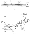
- the side pumping apparatus 140 employs leaky wave pumping of the active medium of a solid state laser 142 to couple light into a multimode fiber 25 via the grating 35 in accordance with known techniques.
- the solid state laser 142 comprises a laser rod 144 having a relativity high index of refraction and including mirrors 146 and 148 configured to create a cavity with a resonant mode therein.
- the multimode fiber 25 is placed against or adjacent to the laser rod 144 in the region 150 where the cladding has been removed from the multimode fiber 25.
- the pump light has access to and is generally parallel to the resonant mode that is formed by the mirrors 148 and 150.
- the pump light 14 from the source 12 is conveyed into the multimode fiber 25 by the grating coupler comprising the grating 35 and the bonding material 37 and propagated to the region 150, it leaky wave couples into the laser rod 144 to excite this gain medium.
- pump light thus leaks out of the low index of refraction multimode fiber 25 into the solid state laser 142 and propagates largely in the longitudinal direction 156.
- the leaky wave coupling can be scaled to generate high pump power by a attaching a large number of fibers to the laser. Redundant fibers improve reliability.
- the length of the coupling section is chosen to optimize the pump light transfer.
- a tapered pump fiber along the area of contact (in a manner similar to that shown in FIG. 7 and denoted in FIG. 10 by dashed lines and designated by the numeral 158), enhances the coupling by bringing low order leaky modes to the surface where they interact with the high index of refraction material comprising the laser rod 144.
- the cavity formed by the mirrors 146 and 148 around the solid state rod 144 emits the lasing light 160.
- This same leaky wave approach utilizing grating coupling can also be used to pump solid state amplifiers or even doped fiber systems.
Landscapes
- Physics & Mathematics (AREA)
- Optics & Photonics (AREA)
- General Physics & Mathematics (AREA)
- Electromagnetism (AREA)
- Engineering & Computer Science (AREA)
- Plasma & Fusion (AREA)
- Lasers (AREA)
Abstract
Description
Claims (12)
- An apparatus for optically pumping an optical fiber from the side comprising:a laser for supplying a beam of pump light;an optical fiber having a longitudinal segment with at least one propagating mode characterized by a propagation angle; anda grating with periodicity disposed on a portion of the longitudinal segment for diffracting said pump light beam at a predetermined angle that is matched to said propagation angle.
- The apparatus as set forth in claim 1, wherein said longitudinal segment comprises a longitudinal surface that is disposed away from said laser.
- The apparatus as set forth in claim 2, wherein said grating comprises a corrugated relief pattern on said longitudinal surface.
- The apparatus as set forth in claim 2, and further comprising a layer formed from a reflective material disposed over said grating for reflecting said beam of pump light.
- The apparatus as set forth in claim 2, wherein said grating has a sawtooth profile.
- The apparatus as set forth in claim 1, and further comprising a bonding material for securing said grating to said longitudinal segment, said bonding material having an index of refraction that is substantially equal to that of said optical fiber.
- The apparatus as set forth in claim 1, wherein said grating comprises a refractive index that varies periodically.
- The apparatus as set forth in claim 7, wherein said grating comprises a plurality of parallel planes that are angularly disposed relative to the longitudinal segment, and wherein the refractive index of said parallel planes varies to enhance input coupling efficiency.
- The apparatus as set forth in claim 1, wherein said optical fiber comprises a multimode fiber.
- An apparatus for optically pumping an optical fiber from the side comprising:a laser for supplying a beam of pump light having a wavelength λ through a medium having an index of refraction n1;an optical fiber having an index refraction n2 and a longitudinal surface and with at least one propagating mode characterized by a propagation angle , said laser forming an incident angle with the line passing normally to the optical fiber; anda grating having a period Λ disposed on a portion of the longitudinal surface for diffracting said beam at the angle that is matched to said propagation angle.
- An apparatus as set forth in claim 10, wherein:
- An apparatus for optically pumping an optical fiber from the side comprising:a plurality of lasers each supplying a beam of pump light;an optical fiber having a longitudinal surface and with at least one propagating mode characterized by a propagation angle; anda plurality of gratings formed on said longitudinal surface for diffracting a respective one of said beams at a predetermined angle, said predetermined angles being matched to said propagation angle.
Applications Claiming Priority (2)
| Application Number | Priority Date | Filing Date | Title |
|---|---|---|---|
| US09/336,656 US6243515B1 (en) | 1999-06-18 | 1999-06-18 | Apparatus for optically pumping an optical fiber from the side |
| US336656 | 2006-01-19 |
Publications (3)
| Publication Number | Publication Date |
|---|---|
| EP1065764A2 true EP1065764A2 (en) | 2001-01-03 |
| EP1065764A3 EP1065764A3 (en) | 2002-04-17 |
| EP1065764B1 EP1065764B1 (en) | 2006-04-05 |
Family
ID=23317074
Family Applications (1)
| Application Number | Title | Priority Date | Filing Date |
|---|---|---|---|
| EP00111944A Expired - Lifetime EP1065764B1 (en) | 1999-06-18 | 2000-06-15 | Apparatus for optically pumping an optical fiber from the side |
Country Status (4)
| Country | Link |
|---|---|
| US (1) | US6243515B1 (en) |
| EP (1) | EP1065764B1 (en) |
| JP (1) | JP2001028468A (en) |
| DE (1) | DE60027087T2 (en) |
Cited By (5)
| Publication number | Priority date | Publication date | Assignee | Title |
|---|---|---|---|---|
| WO2002027871A1 (en) * | 2000-09-27 | 2002-04-04 | Hrl Laboratories, Llc | Compact side-pumped fiber |
| WO2004112206A3 (en) * | 2003-06-16 | 2005-05-12 | Soreq Nuclear Res Ct | Optical apparatus |
| EP1636883A4 (en) * | 2003-05-30 | 2007-07-04 | Bae Systems Information | Multiple emitter side-pumping method and apparatus for fiber lasers |
| US7437033B1 (en) | 2004-05-24 | 2008-10-14 | Hrl Laboratories, Llc | Apparatus and method for pumping optical fiber |
| EP1982220A4 (en) * | 2006-02-07 | 2011-01-19 | Itf Lab Inc | COUPLER WITH EXTERNAL SLEEVE OF MULTIMODES FIBERS AND MULTIGAIN FIBERS |
Families Citing this family (28)
| Publication number | Priority date | Publication date | Assignee | Title |
|---|---|---|---|---|
| FR2789813B1 (en) * | 1999-02-15 | 2001-10-05 | Cit Alcatel | OPTICAL AMPLIFIER |
| US6516104B1 (en) * | 1999-06-25 | 2003-02-04 | Kabushiki Kaisha Toshiba | Optical wiring device |
| US6529318B1 (en) | 2001-08-30 | 2003-03-04 | Np Photonics, Inc. | Total internal reflection (TIR) coupler and method for side-coupling pump light into a fiber |
| JP2003142759A (en) | 2001-11-06 | 2003-05-16 | Toshiba Corp | Fiber laser device and video display device using the same |
| US6721087B2 (en) | 2001-12-13 | 2004-04-13 | Intel Corporation | Optical amplifier with distributed evanescently-coupled pump |
| US7130111B2 (en) * | 2001-12-13 | 2006-10-31 | Intel Corporation | Optical amplifier with transverse pump |
| US6888668B2 (en) | 2001-12-13 | 2005-05-03 | Intel Corporation | Optical amplifier with multiple wavelength pump |
| ATE437378T1 (en) * | 2002-03-15 | 2009-08-15 | Crystal Fibre As | MICROSTRUCTURED OPTICAL FIBER WITH COATING RECESS, METHOD FOR THE PRODUCTION THEREOF AND DEVICE THEREFOR |
| US6975791B2 (en) * | 2002-07-25 | 2005-12-13 | Ceramoptec Industries, Inc. | Fiber laser pumping device |
| US6842570B2 (en) * | 2002-12-11 | 2005-01-11 | Northrop Grumman Corporation | Method for coupling diode array light into an optical fiber |
| JP4216206B2 (en) * | 2004-02-24 | 2009-01-28 | 富士通株式会社 | Optical multiplexing method, optical multiplexer, and optical amplifier using the same |
| CN100345013C (en) * | 2004-11-19 | 2007-10-24 | 东南大学 | Processing method for position and light of built-in tilt Bragg raster containing optical waveguide |
| JP2007158015A (en) * | 2005-12-05 | 2007-06-21 | Hamamatsu Photonics Kk | Excitation light guide member, optical fiber structure and optical device |
| JP2007158012A (en) * | 2005-12-05 | 2007-06-21 | Hamamatsu Photonics Kk | Excitation light guide member, optical fiber structure and optical device |
| JP2007214431A (en) * | 2006-02-10 | 2007-08-23 | Hitachi Cable Ltd | Optical fiber laser |
| JP2007227713A (en) * | 2006-02-24 | 2007-09-06 | Fujikura Ltd | Fusion splicing structure between fibers, optical amplifier and optical fiber laser |
| US7469082B1 (en) * | 2007-09-28 | 2008-12-23 | The Aerospace Corporation | High power optical fiber laser array holographic couplers |
| JP4579283B2 (en) * | 2007-11-20 | 2010-11-10 | 日立電線株式会社 | Optical fiber laser and optical fiber laser excitation method |
| EP2073406B1 (en) * | 2007-12-17 | 2014-02-12 | Siemens Aktiengesellschaft | Machine with optical communication from one machine component to another machine component which is pivotable in relation to the first machine component |
| TW200947002A (en) * | 2008-05-14 | 2009-11-16 | Ind Tech Res Inst | Gratings at optical fiber side and coupling apparatus using the same |
| GB201002740D0 (en) * | 2010-02-17 | 2010-04-07 | Spi Lasers Uk Ltd | Laser apparatus |
| US9310593B2 (en) | 2011-04-18 | 2016-04-12 | Luminit Llc | Holographic solar coupler |
| US10802209B2 (en) | 2013-01-28 | 2020-10-13 | Lumentum Operations Llc | Cladding light stripper |
| GB2511923B (en) | 2013-01-28 | 2018-10-03 | Lumentum Operations Llc | A cladding light stripper and method of manufacturing |
| JP6210732B2 (en) * | 2013-05-24 | 2017-10-11 | 三菱電機株式会社 | Laser amplifier and laser oscillator |
| DE102013009034A1 (en) | 2013-05-28 | 2014-12-04 | Rosenberger Hochfrequenztechnik Gmbh & Co. Kg | Device for coupling light radiation into an optical waveguide |
| US9601904B1 (en) | 2015-12-07 | 2017-03-21 | Raytheon Company | Laser diode driver with variable input voltage and variable diode string voltage |
| US11415751B2 (en) * | 2020-12-17 | 2022-08-16 | Lumentum Operations Llc | Free space coupling of an aiming beam using tapered or grated cladding |
Family Cites Families (8)
| Publication number | Priority date | Publication date | Assignee | Title |
|---|---|---|---|---|
| US4815079A (en) * | 1987-12-17 | 1989-03-21 | Polaroid Corporation | Optical fiber lasers and amplifiers |
| US5061032A (en) | 1989-12-26 | 1991-10-29 | United Technologies Corporation | Optical waveguide embedded light redirecting and focusing bragg grating arrangement |
| US5187760A (en) * | 1992-01-23 | 1993-02-16 | General Instrument Corporation | Wavelength selective coupler for high power optical communications |
| US5511083A (en) * | 1995-03-02 | 1996-04-23 | United Technologies Corporation | Polarized fiber laser source |
| US5854865A (en) * | 1995-12-07 | 1998-12-29 | The United States Of America As Represented By The Secretary Of The Navy | Method and apparatus for side pumping an optical fiber |
| US6052394A (en) * | 1997-09-12 | 2000-04-18 | Samsung Electronics Co., Ltd. | High power pumping device for optical fiber amplification |
| US6490388B1 (en) * | 1999-03-08 | 2002-12-03 | Optigain, Inc. | Side-pumped fiber laser |
| US6229939B1 (en) * | 1999-06-03 | 2001-05-08 | Trw Inc. | High power fiber ribbon laser and amplifier |
-
1999
- 1999-06-18 US US09/336,656 patent/US6243515B1/en not_active Expired - Lifetime
-
2000
- 2000-06-15 DE DE60027087T patent/DE60027087T2/en not_active Expired - Lifetime
- 2000-06-15 EP EP00111944A patent/EP1065764B1/en not_active Expired - Lifetime
- 2000-06-19 JP JP2000182514A patent/JP2001028468A/en active Pending
Cited By (8)
| Publication number | Priority date | Publication date | Assignee | Title |
|---|---|---|---|---|
| WO2002027871A1 (en) * | 2000-09-27 | 2002-04-04 | Hrl Laboratories, Llc | Compact side-pumped fiber |
| EP1636883A4 (en) * | 2003-05-30 | 2007-07-04 | Bae Systems Information | Multiple emitter side-pumping method and apparatus for fiber lasers |
| WO2004112206A3 (en) * | 2003-06-16 | 2005-05-12 | Soreq Nuclear Res Ct | Optical apparatus |
| US7277612B2 (en) | 2003-06-16 | 2007-10-02 | Soreq Nuclear Research Center | Optical apparatus including pump guiding fiber and receiving fiber |
| US7437033B1 (en) | 2004-05-24 | 2008-10-14 | Hrl Laboratories, Llc | Apparatus and method for pumping optical fiber |
| EP1982220A4 (en) * | 2006-02-07 | 2011-01-19 | Itf Lab Inc | COUPLER WITH EXTERNAL SLEEVE OF MULTIMODES FIBERS AND MULTIGAIN FIBERS |
| AU2007214209B2 (en) * | 2006-02-07 | 2012-08-23 | Itf Technologies Inc. | Multimode fiber outer cladding coupler for multi-clad fibers |
| EP2660637A1 (en) * | 2006-02-07 | 2013-11-06 | ITF Laboratories Inc. | Multimode fiber outer cladding coupler for multi-clad fibers |
Also Published As
| Publication number | Publication date |
|---|---|
| US6243515B1 (en) | 2001-06-05 |
| EP1065764B1 (en) | 2006-04-05 |
| EP1065764A3 (en) | 2002-04-17 |
| JP2001028468A (en) | 2001-01-30 |
| DE60027087D1 (en) | 2006-05-18 |
| DE60027087T2 (en) | 2006-08-31 |
Similar Documents
| Publication | Publication Date | Title |
|---|---|---|
| US6243515B1 (en) | Apparatus for optically pumping an optical fiber from the side | |
| EP0883221B1 (en) | Article comprising a cascaded Raman fiber laser | |
| US5337382A (en) | Article comprising an optical waveguide with in-line refractive index grating | |
| US5218655A (en) | Article comprising an optical waveguide with in-line refractive index grating | |
| US6816652B1 (en) | Pump fiber bundle coupler for double-clad fiber devices | |
| US20020197037A1 (en) | Large diameter D-shaped optical waveguide and coupler | |
| US6795611B2 (en) | Light coupling between a light source and an optical waveguide | |
| JP2007249213A (en) | Method and apparatus for side pumping optical fiber | |
| BR9915953A (en) | Fiber optic device enclosed in a tube, method for enclosing an optical reflective element in a tube, and optical reflective element enclosed in a tube | |
| US20090285528A1 (en) | Cladding grating and fiber side-coupling apparatus using the same | |
| JPH10104454A (en) | Device consisting of optical waveguide | |
| JP5688565B2 (en) | Fiber laser apparatus and optical amplification method | |
| US6337939B1 (en) | Optical amplifier monitor using a blazed grating | |
| US7106928B2 (en) | Coupling high power optical sources to small diameter fibers | |
| US20050281508A1 (en) | System and method for introducing pump radiation into high-power fiber laser and amplifier | |
| US6904198B2 (en) | Device for coupling light into the fiber | |
| JP4212724B2 (en) | Optical amplifier | |
| JP2004507782A (en) | Fiber optic bus, modulator, detector and emitter using cladding mode coupling | |
| US6532107B2 (en) | Optical amplifier, light source module and optical system | |
| WO2003017440A2 (en) | Optical amplification system | |
| WO2020203136A1 (en) | Fiber laser device | |
| JPH1039149A (en) | Optical waveguide type diffraction grating and optical fiber amplifier | |
| JP4846770B2 (en) | Optical amplifier | |
| JP2002084023A (en) | Optical fiber amplifier, excitation light source module and optical system | |
| Su et al. | Multimode fiber Bragg grating based fiber lasers and optical sensors |
Legal Events
| Date | Code | Title | Description |
|---|---|---|---|
| PUAI | Public reference made under article 153(3) epc to a published international application that has entered the european phase |
Free format text: ORIGINAL CODE: 0009012 |
|
| AK | Designated contracting states |
Kind code of ref document: A2 Designated state(s): AT BE CH CY DE DK ES FI FR GB GR IE IT LI LU MC NL PT SE Kind code of ref document: A2 Designated state(s): DE FR GB NL |
|
| AX | Request for extension of the european patent |
Free format text: AL;LT;LV;MK;RO;SI |
|
| PUAL | Search report despatched |
Free format text: ORIGINAL CODE: 0009013 |
|
| AK | Designated contracting states |
Kind code of ref document: A3 Designated state(s): AT BE CH CY DE DK ES FI FR GB GR IE IT LI LU MC NL PT SE |
|
| AX | Request for extension of the european patent |
Free format text: AL;LT;LV;MK;RO;SI |
|
| RIC1 | Information provided on ipc code assigned before grant |
Free format text: 7H 01S 3/067 A, 7G 02B 6/42 B, 7H 01S 3/094 B |
|
| 17P | Request for examination filed |
Effective date: 20020711 |
|
| AKX | Designation fees paid |
Free format text: DE FR GB NL |
|
| 17Q | First examination report despatched |
Effective date: 20030926 |
|
| RAP1 | Party data changed (applicant data changed or rights of an application transferred) |
Owner name: NORTHROP GRUMMAN CORPORATION |
|
| RAP1 | Party data changed (applicant data changed or rights of an application transferred) |
Owner name: NORTHROP GRUMMAN CORPORATION |
|
| GRAP | Despatch of communication of intention to grant a patent |
Free format text: ORIGINAL CODE: EPIDOSNIGR1 |
|
| GRAS | Grant fee paid |
Free format text: ORIGINAL CODE: EPIDOSNIGR3 |
|
| GRAA | (expected) grant |
Free format text: ORIGINAL CODE: 0009210 |
|
| AK | Designated contracting states |
Kind code of ref document: B1 Designated state(s): DE FR GB NL |
|
| PG25 | Lapsed in a contracting state [announced via postgrant information from national office to epo] |
Ref country code: NL Free format text: LAPSE BECAUSE OF FAILURE TO SUBMIT A TRANSLATION OF THE DESCRIPTION OR TO PAY THE FEE WITHIN THE PRESCRIBED TIME-LIMIT Effective date: 20060405 |
|
| REG | Reference to a national code |
Ref country code: GB Ref legal event code: FG4D |
|
| REF | Corresponds to: |
Ref document number: 60027087 Country of ref document: DE Date of ref document: 20060518 Kind code of ref document: P |
|
| PGFP | Annual fee paid to national office [announced via postgrant information from national office to epo] |
Ref country code: FR Payment date: 20060620 Year of fee payment: 7 |
|
| PGFP | Annual fee paid to national office [announced via postgrant information from national office to epo] |
Ref country code: GB Payment date: 20060626 Year of fee payment: 7 |
|
| NLV1 | Nl: lapsed or annulled due to failure to fulfill the requirements of art. 29p and 29m of the patents act | ||
| ET | Fr: translation filed | ||
| PLBE | No opposition filed within time limit |
Free format text: ORIGINAL CODE: 0009261 |
|
| STAA | Information on the status of an ep patent application or granted ep patent |
Free format text: STATUS: NO OPPOSITION FILED WITHIN TIME LIMIT |
|
| 26N | No opposition filed |
Effective date: 20070108 |
|
| GBPC | Gb: european patent ceased through non-payment of renewal fee |
Effective date: 20070615 |
|
| REG | Reference to a national code |
Ref country code: FR Ref legal event code: ST Effective date: 20080229 |
|
| PG25 | Lapsed in a contracting state [announced via postgrant information from national office to epo] |
Ref country code: GB Free format text: LAPSE BECAUSE OF NON-PAYMENT OF DUE FEES Effective date: 20070615 |
|
| PG25 | Lapsed in a contracting state [announced via postgrant information from national office to epo] |
Ref country code: FR Free format text: LAPSE BECAUSE OF NON-PAYMENT OF DUE FEES Effective date: 20070702 |
|
| PGFP | Annual fee paid to national office [announced via postgrant information from national office to epo] |
Ref country code: DE Payment date: 20110622 Year of fee payment: 12 |
|
| REG | Reference to a national code |
Ref country code: DE Ref legal event code: R082 Ref document number: 60027087 Country of ref document: DE Representative=s name: WUESTHOFF & WUESTHOFF PATENT- UND RECHTSANWAEL, DE |
|
| REG | Reference to a national code |
Ref country code: DE Ref legal event code: R082 Ref document number: 60027087 Country of ref document: DE Representative=s name: WUESTHOFF & WUESTHOFF PATENT- UND RECHTSANWAEL, DE Effective date: 20120814 Ref country code: DE Ref legal event code: R081 Ref document number: 60027087 Country of ref document: DE Owner name: NORTHROP GRUMMAN SYSTEMS CORPORATION, US Free format text: FORMER OWNER: NORTHROP GRUMMAN CORP., LOS ANGELES, US Effective date: 20120814 |
|
| REG | Reference to a national code |
Ref country code: DE Ref legal event code: R119 Ref document number: 60027087 Country of ref document: DE Effective date: 20130101 |
|
| PG25 | Lapsed in a contracting state [announced via postgrant information from national office to epo] |
Ref country code: DE Free format text: LAPSE BECAUSE OF NON-PAYMENT OF DUE FEES Effective date: 20130101 |